Employee injury
Canadian Pacific Railway
Hi-rail crane boom failure
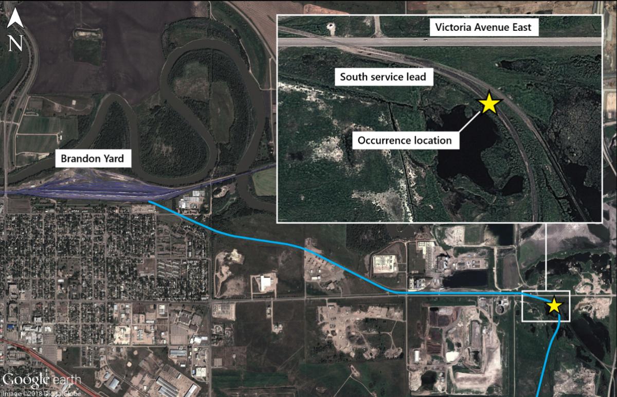
South service lead track
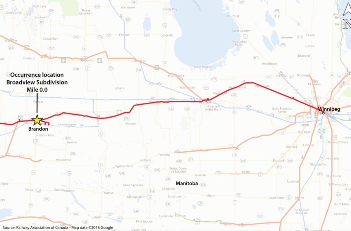
Mile 0.0, Broadview Subdivision
Brandon, Manitoba
The Transportation Safety Board of Canada (TSB) investigated this occurrence for the purpose of advancing transportation safety. It is not the function of the Board to assign fault or determine civil or criminal liability. This report is not created for use in the context of legal, disciplinary or other proceedings. See Ownership and use of content. Masculine pronouns and position titles may be used to signify all genders to comply with the Canadian Transportation Accident Investigation and Safety Board Act (S.C. 1989, c. 3).
Summary
On 02 September 2017, at about 1505 Central Daylight Time, a Canadian Pacific Railway Engineering Services work crew was using a truck-mounted boom crane to unload tie plates from a 10-ton hi-rail truck stationed on the south service industrial lead track in Brandon Yard, Manitoba. To operate the controls, the crane operator was sitting in an elevated metal crane operator’s basket secured to the crane column. During a lift, the crane column failed and the crane boom dropped, throwing the crane operator onto the track, about 12 feet below. The crane operator sustained serious injuries and was transported to hospital by ambulance.
Le présent rapport est également disponible en français.
1.0 Factual information
On 02 September 2017, at 0700,Footnote 1 a Canadian Pacific Railway (CP) Engineering Services work crew based in Winnipeg, Manitoba, began its shift with a job briefing. The work crew was to drive to Brandon, Manitoba (Figure 1), in a crew-cab half-ton truck and a material-handling truck (CP serial number EO7029).
The material-handling truck was a 10-ton commercial platform truck manufactured by Freightliner in 2007. The truck was equipped with hydraulic hi-rail wheels that allowed it to operate on the rails as a track unit. The truck was regularly maintained and was in good mechanical condition.
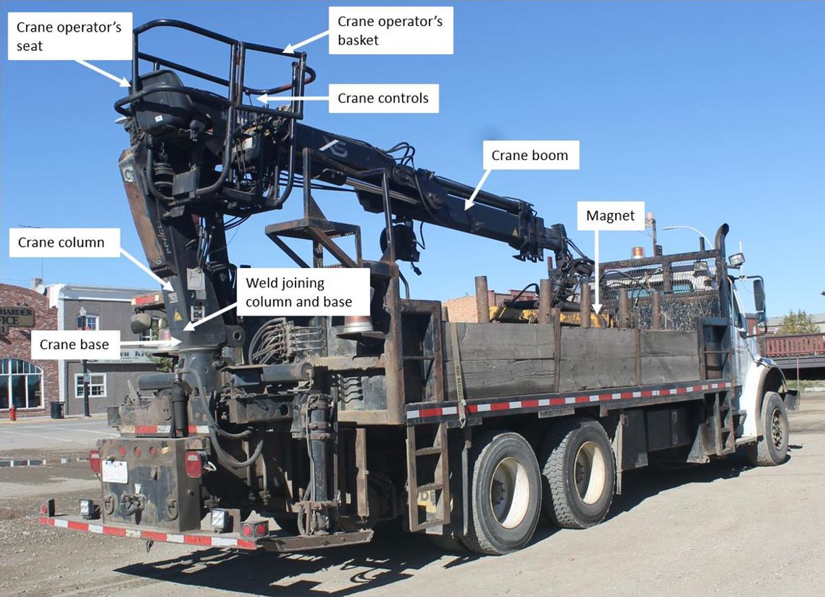
The truck was also equipped with a Hiab model 144 B-3 CL articulating boom crane, manufactured in August 2006. The crane, which had a 3900 kg lift capacity, was mounted on the rear of the truck behind the loading deck. The crane consisted of a column, an inner boom, an outer boom with hydraulic and manual extensions, and hydraulic cylinders.
The crane controls and the operator's seat were contained within an elevated metal crane operator's basket attached to the crane column. Controls to operate cranes come in many different configurations. Not all boom cranes are equipped with a basket. For this truck, the arrangement for the basket, operator's seat, and crane controls had been designed by Hiab in conjunction with CP Engineering.
The truck and crane were used regularly for various Engineering Services work crew tasks.
1.1 The accident
Upon arrival in Brandon, the work crew began its work. The work crew picked up tie plates from Brandon Yard and distributed them to various locations throughout the terminal using the crane. To perform this task, the tie plates were loaded onto the truck deck and driven to the required location. Loading and unloading the tie plates was done using a large magnet (about 1 m in diameter) attached to the end of the crane. When tie plates were being distributed next to the rail, the truck was stationary on the track, with the crane operator seated in the basket (Figure 2).
The work crew distributed a first load of tie plates, then reloaded the truck with a second load. At about 1505, the work crew was unloading the second load of tie plates on the right‑of-way behind the truck on the south service lead track.
The operator lifted about 10 tie plates from the truck deck and swung the crane around to face the rear to put down the tie plates. The operator was about to put the tie plates down when the crane column failed where it was welded to the crane base. The extended crane boom dropped, and the operator was thrown from the basket onto the track, about 12 feet below. Several members of the work crew immediately attended to the operator, while others called for emergency services. The operator sustained serious injuries and was transported to hospital by ambulance.
At the time of the occurrence, the temperature was 23° C, the winds were from the northwest gusting up to 54 km/h, and the sky was clear.
1.2 Post-accident examination
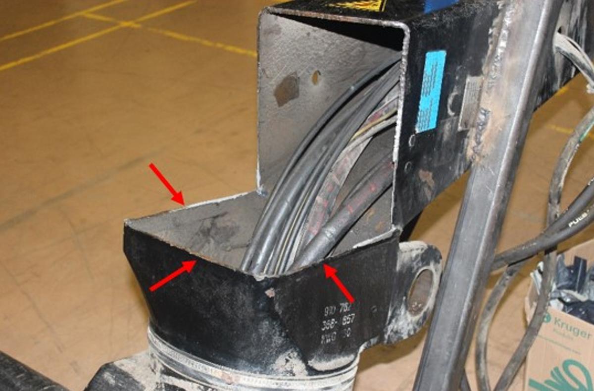
A post-accident visual examination conducted at CP's Weston Shops in Winnipeg revealed that the crane column failed as a result of the failure of a weld that joined the column to the crane base. The fracture appeared to originate at the toe of the weld, on the interior of the column (Figure 3).
The examination also found that the buckle portion of the operator's seatbelt was missing, the locking mechanism of the operator's seat was missing several parts, and a support piece of the frame on the underside of the bottom of the operator's basket was broken.
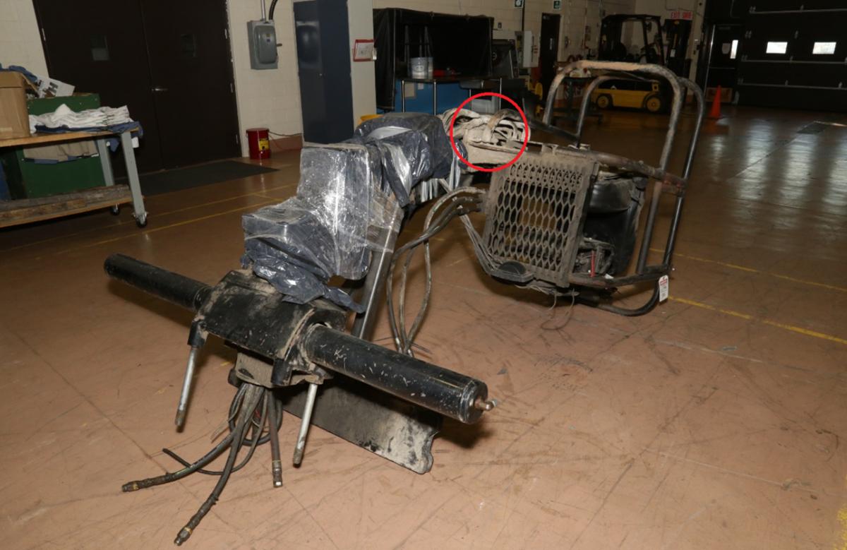
The crane boom assembly was sent to the TSB Engineering Laboratory in Ottawa, Ontario, for failure analysis (see Section 1.8, TSB laboratory examination).
1.3 Work crew information
The work crew consisted of 6 CP employees, who were supervised remotely by an engineering supervisor. All crew members were qualified for their respective positions, met fitness and rest standards, and were familiar with the territory and the work associated with the assigned task. The crane operator qualified in 2015 and had worked on a crane for a few months.
1.4 Track information
Brandon Yard is located at Mile 0.0 of CP's Broadview Subdivision, which extends from Brandon (Mile 0.0) to Broadview, Saskatchewan (Mile 130.0). The south service lead is a yard track that extends from Brandon Yard southeast to an industrial service area in east Brandon (Figure 4).
1.5 Previous accident involving the truck
On 18 March 2015, a CP train collided with the rear end of the truck involved in this occurrence.Footnote 2 A work crew had operated the truck in hi-rail mode as a track unit during the day and parked it for the night on the track, in a siding at Mile 25.7 of the Estevan Subdivision, near Menteith, Manitoba.
When the truck is parked for any length of time, the crane is extended toward the front of the truck and secured to the deck. The rear of the crane column and the crane base are then facing toward the rear of the truck (Figure 2).
At approximately 0400, CP train P36-16 was proceeding westward on the Estevan Subdivision with 3 locomotives and 1 load of grain when it encountered a main-track switch in the abnormal position (lined against the train) at Menteith. The train crew initiated an emergency brake application, but the train was unable to stop before entering the siding at about 20 mph. The train collided with the rear end of the unoccupied truck at about 14 mph.
The impact of the collision derailed the truck. The rear of the truck was severely damaged and required extensive repairs. The crane was also damaged, requiring repairs and recertification. Once the truck and the crane were repaired and recertified in June 2015, both were returned to service.
1.6 Crane information
CP has 635 boom cranes of various sizes in service throughout its fleet of vehicles and work equipment. The average service life of a CP truck is about 13 years, depending on use. Hiab recommends crane replacement after 10 years. Once a truck reaches the end of its service life, CP typically replaces the truck and the crane at the same time.
The occurrence crane was the only crane in CP's fleet to have experienced an in-service column failure in the preceding 5 years. Following the occurrence, CP inspected all its boom cranes, and no defects were noted.
Since 2006, Hiab has sold about 360 of these cranes (model 144 B-3 CL) in Canada. During that time, there had been no other column failures reported.
1.7 Crane inspections
Crane inspections have stringent requirements and are regulated in Canada by both provincial and federal authorities. CP, as a federally regulated company, must comply with the Canadian Occupational Safety and Health Regulations (COSH). Under section 14.21 of the regulations, mobile cranes are required to be inspected, tested, and maintained in accordance with theCanadian Standards Association (CSA) Standard Z150-1974, Safety code on mobile cranes.Footnote 3
Only a competent person who has the requisite training and certification can conduct a crane inspection. Any necessary repairs made to a crane must be approved and supervised by a professional engineer.
1.7.1 Canadian Standards Association Z150-16 Safety code on mobile cranes
CAN/CSA Z150-16, Safety code on mobile cranes, is designed to
- guard against and minimize injury to workers, and otherwise provide for the protection of life, limb, health, and property, by specifying minimum safety requirements for mobile cranes;
- provide direction and guidance to manufacturers and buyers of mobile cranes regarding the minimum standards expected of such machines in Canada;
- provide direction and guidance to owners, employers, supervisors, workers, users, and others concerned with, responsible for, or involved in the application and use of mobile cranes; and
- guide Canadian federal, provincial/territorial, and other regulatory bodies in the development and promulgation of appropriate health and safety legislation and directives concerning mobile cranes.Footnote 4
Clause 5 of the standard, “Inspection, testing, and maintenance,” states in part:
5.1 General
5.1.1
All cranes shall be inspected, tested, and maintained in accordance with the manufacturer's recommendations and the requirements of Clause 5 or as specified by the manufacturer's manual unless otherwise approved by the original equipment manufacturer or an engineer.
5.1.2
A complete and concise record of any information concerning inspections, tests, maintenance, and repairs that have a direct bearing on the safety of the crane shall be kept permanently in a usable format, called a “crane log” (see Clause 5.2).
5.1.3
Inspection, testing, and maintenance shall be performed by a competent person(s).
[…]
5.3 Inspection
5.3.1 General
The owner shall ensure that all new, used, altered, or repaired cranes be inspected in accordance with the original equipment manufacturer's specifications and are in compliance with the provisions of Clause 5. No crane shall be put into operation until it has been inspected throughout and until any defects or hazards detected by such inspection that could limit the safe performance of the crane have been eliminated.
[…]
5.3.2.2 Regular inspection
The inspection procedure for cranes in regular service shall be divided into four classifications of regular inspection intervals. The intervals, in turn, shall depend upon the nature of the critical components of the crane and the degree of their exposure to wear, deterioration, or malfunction. The four classifications of regular inspections intervals shall be as follows:
- daily inspection as specified in Clause 5.3.3;
- periodic inspection — at three-month intervals, at every 350 h of machine time, or as specifically recommended by the original equipment manufacturer as specified in Clause 5.3.4;
- annual inspection (by the end of the twelfth month following the previous inspection); and
- complete structural inspection of telescopic boom, as follows:
- at any time that damage to the boom or defect is discovered that affects structural competence (boom disassembly is only required to the extent required to repair the boom or defect);
- at any time the boom is disassembled; or
- at the interval specified by the manufacturer.Footnote 5
The requirements and the components to inspect are detailed in extensive lists for each type of inspection. Among other things, Clause 5.3.3 of the standard requires the daily inspection of
- control mechanisms, for excessive wear of components and contamination by lubricants or other foreign matter;
- safety devices, for malfunction;Footnote 6
1.7.2 Canadian Pacific Railway crane inspections
CP boom cranes are inspected daily, quarterly, and annually. A checklist must be completed for each inspection and kept with the vehicle. Daily inspections are conducted by each crane operator before it is used. Quarterly inspections are performed by CP work equipment personnel and include all of the daily inspection items and other items specific to the quarterly inspection. Annual inspections are required for crane recertification and include all of the daily and quarterly inspection items in addition to non-destructive testing (NDT) of critical areas and components, such as the crane boom and the column.
Any defect or non-conformance identified during an inspection must be repaired. Structural crane repairs are performed under the direction of a registered professional engineer and must be certified as safe before a crane can return to service.
For boom cranes equipped with a basket, Clause 5.3.3 of CAN/CSA-Z150-16 requires safety devices to be inspected daily for malfunction. Such devices would generally include the basket (which provides fall protection), the operator's seat, and controls to ensure that safety equipment (such as pins to secure the seat in place and an operator's seatbelt) are in working order. CP requires operators to wear seatbelts when operating a crane from a basket.Footnote 7
Under item D2 (Crane) on the CP daily inspection checklist for the crane, there is a requirement to check all safety devices for proper operation. However, at the time of the accident, some of the safety features of the crane operator's seat and basket were inoperative. The investigation determined that when employees inspected the crane, they did not interpret item D2 as applying to the seat. The checklist also includes a fibreglass basket (item D18) and a metal basket (item D19) as items requiring inspection. However, these items were not initialled by an inspector; they were marked as not applicable (N/A). CP stated that these items did not apply to the crane's basket and operator's station, as they referred to a single-person fibreglass or metal basket on the end of a truck-mounted crane (similar to the basket used by hydro workers to repair hydro lines). Therefore, inspection of the boom crane's basket, seat securement, and seatbelt were not listed on the CP crane inspection checklist.
1.7.3 Non-destructive testing inspection of cranes
CP subcontracts some of the required non-destructive testing (NDT) crane inspection work to AXIS Inspection Group Limited (AXIS), located in Winnipeg. AXIS has qualified inspectors and works with Proforma Engineering Limited to ensure that any defects identified during an NDT inspection are repaired. Following a crane repair, an additional NDT inspection is conducted to ensure the integrity of the repair before a crane can be certified and returned to service.
The NDT method used for crane inspection is magnetic particle inspection (MPI). MPI is performed using a handheld probe and powder containing finely divided ferromagnetic particles. MPI can be used to locate surface and subsurface discontinuities in ferromagnetic materials. When discontinuities in the part lie in a transverse direction to the magnetic field created by the inspection equipment, a disturbance of the magnetic field can be viewed by applying the particles over the surface. The disturbance in the field will gather and hold some of the particles, and the collection of these particles will form an outline of the discontinuity.Footnote 8
On 19 April 2017, the crane had been inspected by AXIS. There were no defects noted, and the crane was recertified. The AXIS inspection did not include an examination of the basket, the operator's seat, or related securements because AXIS does not consider the basket to be part of the crane. The AXIS inspection checklist did not include these items.
1.8 TSB laboratory examination of crane column
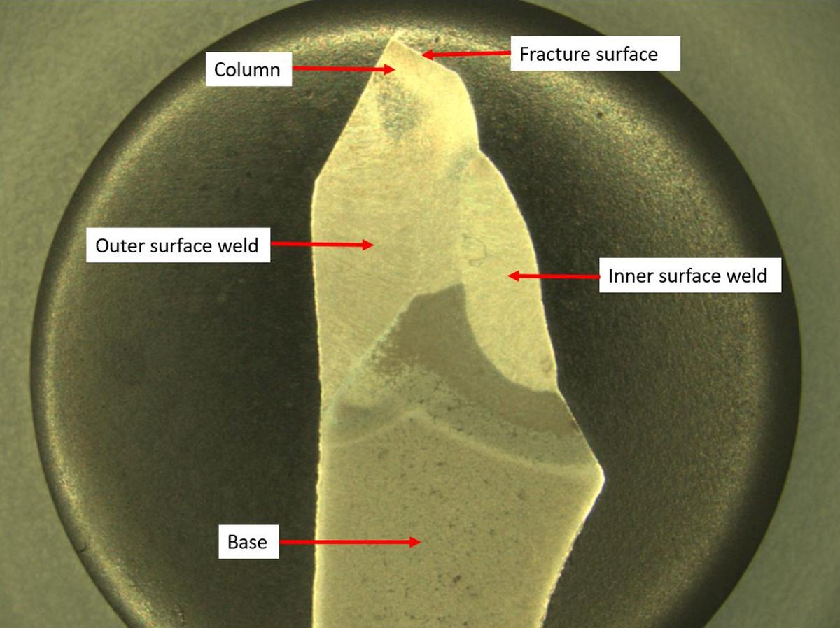
Visual examination of the failed crane column revealed that the failure occurred in the welded region that joined the column and the crane base. The fracture originated in the heat‑affected zone at the toe of the weld, on the interior of the column. The fracture surface had two distinct regions with different appearances. One region was flat and perpendicular to the axis of the column, and the other region had a 45-degree slanted surface (Figure 5).
The flat region exhibited multiple small semi-elliptical features that originated on the inner surface of the fracture and had progressed toward the outer surface of the column's rear and side walls (Figure 6).
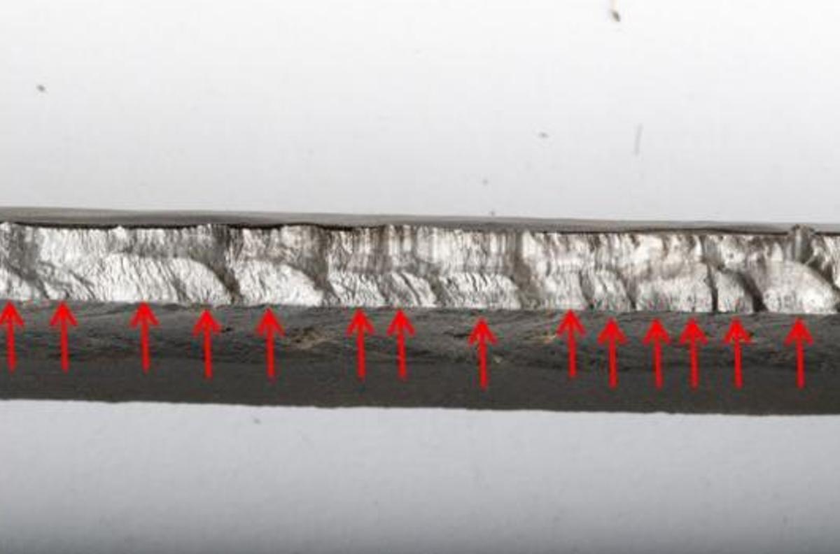
The semi-elliptical features are typically associated with multiple origins of fatigue cracks. A small number of the flat regions had an oxidized appearance, suggesting that they had been exposed to moisture for some time before the failure (Figure 7).
Extensive rubbing damage was also observed. This type of damage occurs when 2 fracture surfaces repeatedly come into contact with each other, typically occurring when under load (e.g., during loading of the column).
The 45-degree slanted region was relatively small and displayed features that are typically associated with final overstress rupture.
The condition of the fracture surface suggests that the cracking had most likely been present for some time before the failure and may have been present at the time of the last annual inspection in April 2017.
1.8.1 Metallurgical, hardness, and elemental testing
Metallurgical examination of the weld cross-section determined that there were 2 welds: 1 weld on the inner column surface and 1 weld on the outer surface (Figure 8). Both welds were homogeneous and had good penetration. The different microstructures of the column and base parent metals, the weld bead, and the heat-affected zones were typical for this type of welding.
Hardness testing and elemental analysis of the column steel determined that it met the required specifications provided by Hiab.
1.8.2 Examination of the crane operator's basket and related components
1.8.2.1 Operator's seatbelt
The crane operator's seat was equipped with a single seatbelt that strapped around the operator's hips and thighs to secure the operator to the seat. However, the buckle portion of the seatbelt system was missing, rendering the seatbelt system inoperative. Dust or dirt was present on the seatbelt assembly, suggesting that the buckle had been missing for some time. The remaining portion of the seatbelt contained the seatbelt tongue, which was covered in dirt.
1.8.2.2 Securement of the operator's seat
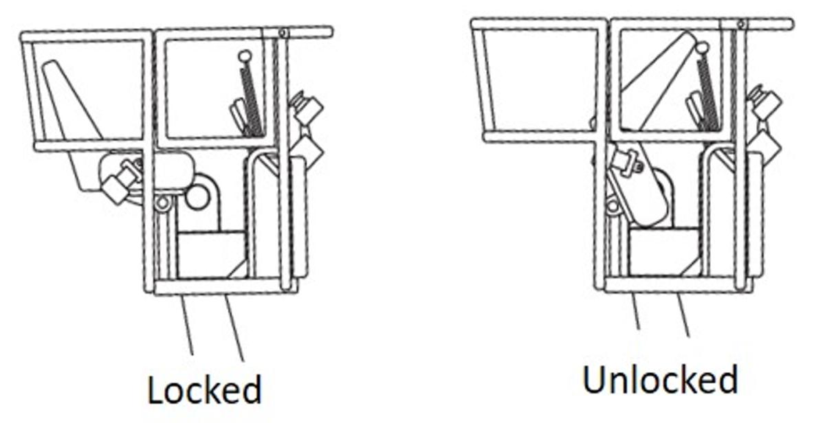
The operator's seat design includes a locking mechanism that is meant to prevent the seat from pivoting up and forward (Figure 9). However, at the time of the occurrence, the operator's seat was in the forward hinged position. The seat-locking mechanism had missing parts, was inoperative, and was covered in dirt, suggesting that the locking mechanism had been inoperative for some time.
1.8.2.3 Crane controls
The crane controls were located forward of the operator's seat. The controls were positioned such that, had the seatbelt been operative but the seat-locking mechanism inoperative at the time of the failure, it is likely that the operator would have been rotated up and forward in the seat onto the crane controls, which would have also likely caused serious injuries.
1.8.2.4 Operator's basket
A support piece of the frame on the underside of the bottom of the operator's basket was broken, corroded, and covered in dirt (Figure 10 and Figure 11).

1.8.3 Non-destructive testing using magnetic particle inspection
Although the MPI detection method used for NDT of the crane has some limitations, this method, along with visual inspection, is an industry standard for crane inspection and recertification due to practicality.
1.8.3.1 Presence of paint
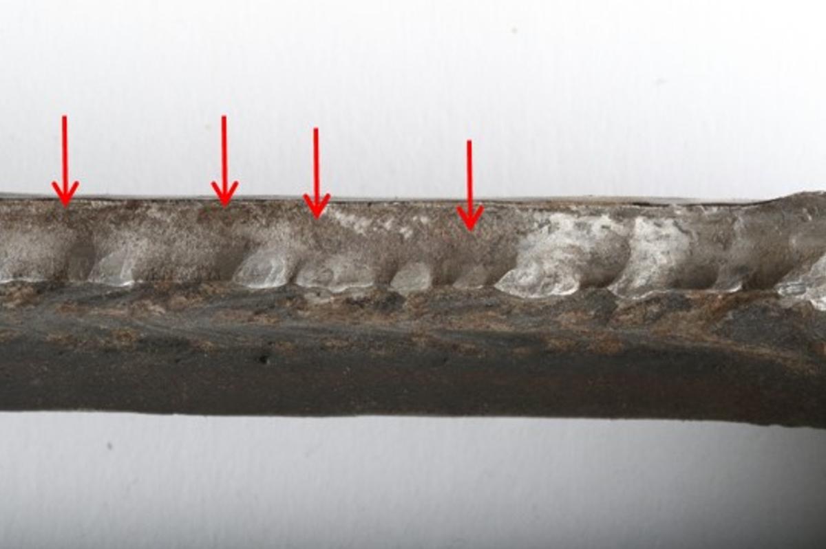
On the crane, the paint measured about 0.0065 inches thick in the weld region. The paint was generally intact, with the exception of a number of small areas of corrosion (Figure 7). In the corroded areas, the paint was likely breached before the column failed. The breach in the coating exposed small localized areas of steel to the environment and resulted in oxidation.
The presence of paint would have presented a challenge for the type of NDT inspection method (MPI) used to inspect the weld on the crane column. This method may not be able to inspect a part through a thin coating of paint. It is not current industry practice for paint to be removed when inspecting boom cranes.
1.8.3.2 Location and orientation of defect
Cracking had begun on the inside surface of the crane column. However, the crack would have needed to propagate through almost the entire thickness of the rear column wall for the MPI method to detect the defect reliably.
1.8.3.3 Magnetism
For an MPI to be as effective as possible, the surface being tested needs to be demagnetized before it is inspected. However, it is not industry practice to demagnetize the surface of industrial boom cranes before inspection; not demagnetizing the surface is considered to be adequate for cranes exposed to normal operating conditions.
Magnetization can occur as a result of a welding process, MPI inspection, rubbing action or operation of an electromagnetic attachment, all of which can leave residual magnetism. When residual magnetism is present, the sensitivity of the test can be reduced; also, it could produce false indications, in which case a second test would be conducted.
The weld that joined the occurrence column to the base was found to be magnetized when it arrived at the TSB Engineering Laboratory.
1.8.4 Finite element analysis
Finite element analysis was conducted to model the forces acting on the fatigue crack of the failed column and to examine the stress level at the column-to-base weld during normal operations. The analysis determined that
- With the existing fatigue crack, the crane's load capacity was reduced by about 60% before factoring in any safety margin.
- Without the existing fatigue crack, the maximum stress would have been within the stress limits for the entire weld with the boom at an angle below 60 degrees relative to the ground.
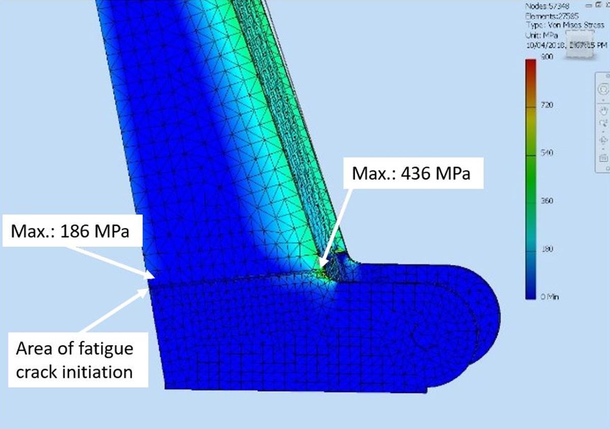
- Without the existing fatigue crack, with the boom raised at or above 60 degrees, the stress would have increased by about 64%. The highest stress recorded was 436 megapascals (MPa), which was located at the corner of the front and side walls of the column. This area of highest stress is not in the area where the initial cracking was observed in the failed crane column (Figure 12).
1.9 TSB laboratory reports
The TSB completed the following laboratory reports in support of this investigation:
- LP216/2017 – Boom Crane Failure Analysis – HIAB Hydraulic Boom Crane Model 144-B
- LP014/2018 – Boom Crane Modelling – HIAB Hydraulic Boom Crane Model 144-B
2.0 Analysis
The accident occurred during a routine Engineering Services work crew task involving the unloading of tie plates from a material-handling truck, using a boom crane. The material properties of the steel and the weld joining the crane column to the base of the crane met the manufacturer's specifications. The analysis will focus on the failure of the crane column; the damage sustained by the truck/crane due to a rear-end collision with a train; inspection and maintenance of operator's seatbelt, seat securement, and basket; and non-destructive testing (NDT).
2.1 The accident
The accident occurred when a crane operator was unloading tie plates on the right-of-way on the south service industrial lead track in the Brandon Yard. The operator lifted about 10 tie plates from the truck deck and swung the crane around to face the rear to put down the tie plates behind the truck. The crane column failed in the welded region that joined the column to the crane base. The extended crane boom dropped and the operator was thrown from the basket onto the track, about 12 feet below, sustaining serious injuries.
Multiple fatigue cracks had originated in the heat-affected zone at the toe of the weld, on the interior of the column, and propagated outward through the rear and side column walls. The final column failure occurred when the fatigue cracking reached a critical size and the column could no longer sustain the service load.
Finite element analysis, the extent of the fatigue cracking, the extensive rubbing damage observed on the fracture surface and the small size of the final overstress rupture area were indicators that crack growth had been slow and that the loads applied to the area of the crane where the fracture originated were relatively low.
A small number of the fatigue cracks open to the exterior column surface had an oxidized appearance, suggesting that they had been exposed to moisture for some time before the failure. The length of time that some of the small fractures were exposed to the exterior column surface could not be determined.
2.2 Previous collision damage
The crane was the only one in Canadian Pacific Railway's (CP) fleet of 635 boom cranes to have experienced an in-service column failure in the preceding 5 years. Since 2006, Hiab had sold about 360 of these cranes (model 144) in Canada. No column failures for this type of crane had previously been reported. Furthermore, the material properties of the steel and the weld joining the crane column to the base met the manufacturer's specifications. Given the unique nature of the failure, it is likely that some unusual loading of the column on the occurrence crane had occurred and had initiated the cracking on the inner column surface, which then grew in fatigue.
In March 2015, a CP train had collided with the rear end of the occurrence truck, causing impact damage that required extensive repairs. The truck and the crane were repaired, recertified, and returned to service. It is likely that the force of the collision had placed a high load on the rear inner surface of the column.
The impact likely initiated multiple cracks in the heat-affected zone at the toe of the weld on the interior of the column. If these multiple small cracks were present on the inner surface of the column when the crane was recertified in 2015 and during subsequent annual inspections, they would have been difficult to detect, given the limitations of the MPI technique and the location of the cracking.
2.2.1 Effect of magnetism
To optimize an MPI, the surface being tested needs to be demagnetized before inspection. Magnetization can occur as a result of a welding process, an MPI, rubbing action, or operation of an electromagnetic attachment; all of these can leave residual magnetism. If a surface that is being tested using the MPI technique is not checked to ensure it has been demagnetized before testing, there is an increased risk that the sensitivity of the test will be reduced or even produce false indications.
2.3 Inspection and maintenance of operator's seatbelt, seat securement, and basket
CP inspects its boom cranes daily, quarterly, and annually. A checklist must be completed for each inspection and maintained with the vehicle. Annual inspections are required for crane recertification and include all items outlined for the daily and quarterly inspections in addition to NDT of critical areas and components, such as the crane boom and the column. Items identified as defective during inspection are required to be repaired.
For boom cranes equipped with a basket, Section 5.3.3 of Z150 requires the daily inspection of safety devices for malfunction. Such devices would generally include the basket which provides fall protection, the operator's seat, and controls to ensure that safety equipment such as pins to secure the seat in place and an operator's seatbelt are in working order. CP requires operators to wear seatbelts when operating a crane from a basket.
The CP daily inspection checklist for the crane listed a requirement (D2 Crane) to check all safety devices for proper operation. However, at the time of the accident, some of the safety features of the crane operator's seat and basket were inoperative, suggesting that they were not being inspected. The checklist also includes a fibreglass basket (item D18) and a metal basket (item D19) as items requiring inspection: the items referred to a single-person fibreglass or metal basket on the end of a truck-mounted crane and did not apply to the crane's basket and operator's station. Therefore, inspection of the crane's basket, seat securement, and seatbelt were not listed on the CP crane inspection checklist.
CP had subcontracted some of the required annual crane inspection NDT work to AXIS Inspection Group Limited (AXIS). AXIS inspected and recertified the crane on 19 April 2017, with no defects noted. However, the AXIS inspection did not include an examination of the basket. Neither CP nor AXIS included the inspection of the basket, the operator seat securement, or the seatbelt on its crane inspection checklist. If the basket, the operator seat securement, and the seatbelt of a boom crane are neither regularly inspected nor appropriately maintained, there is an increased risk of operator injury in the event of an accident.
The operator's seatbelt, the seat securement, the controls, and the basket were not properly inspected or maintained and were generally in a state of disrepair. Specifically,
- The buckle portion of the seatbelt system was missing, rendering the seatbelt system inoperative.
- The seat-locking mechanism was missing parts and inoperative. With the locking mechanism inoperative, the operator could not lock the seat in place to prevent it from moving up and forward in the event of a boom column failure.
- A support piece of the frame on the underside of the bottom of the operator's basket was broken and corroded.
- All of these components were covered in dirt, indicating that they had been in this condition for an extended period of time.
The operator's seatbelt and the seat-locking mechanism were inoperative, resulting in the operator being thrown out of the seat onto the track below when the crane column failed, which contributed to the operator's injuries.
3.0 Findings
3.1 Findings as to causes and contributing factors
- While tie plates were being unloaded, the crane column failed in the welded region that joined the column to the crane base.
- The extended crane boom dropped and the operator was thrown from the basket onto the track, about 12 feet below; the operator sustained serious injuries.
- Multiple fatigue cracks had originated in the heat-affected zone at the toe of the weld, on the interior of the crane column, and propagated outward through the rear and side column walls.
- The final column failure occurred when the fatigue cracking reached a critical size and the column could no longer sustain the service load.
- The impact from a prior collision with a train likely initiated multiple cracks in the heat-affected zone at the toe of the weld on the interior of the column.
- The operator's seatbelt and the seat-locking mechanism were inoperative, resulting in the operator being thrown out of the seat onto the track below when the crane column failed, which contributed to the operator's injuries.
3.2 Findings as to risk
- If a surface that is being tested using the magnetic particle inspection technique is not checked to ensure it has been demagnetized before testing, there is an increased risk that the sensitivity of the test will be reduced or even produce false indications.
- If the basket, the operator seat securement, and the seatbelt of a boom crane are neither regularly inspected nor appropriately maintained, there is an increased risk of operator injury in the event of an accident.
3.3 Other findings
- Finite element analysis, the extent of the fatigue cracking, the extensive rubbing damage observed on the fracture surface, and the small size of the final overstress rupture area were indicators that crack growth had been slow and that the loads applied to the area of the crane where the fracture originated were relatively low.
- The length of time that some of the small fractures were exposed to the exterior column surface could not be determined.
- If these multiple small cracks were present on the inner surface of the column when the crane was recertified in 2015 and during subsequent annual inspections, they would have been difficult to detect given the limitations of the magnetic particle inspection technique and the location of the cracking.
4.0 Safety action
4.1 Safety action taken
4.1.1 Canadian Pacific Railway
Immediately following the occurrence, Canadian Pacific Railway undertook inspections of all boom cranes across its system that had not already been scheduled for inspection or were not already in the process of being inspected. No defects were reported.
In October 2018, Canadian Pacific Railway revised its crane inspection procedures relating to the operator's seat. The updated inspection procedures include the following:
- Daily inspections: Inspect the operator's seat assembly for any looseness, wear or defects. Including but not limited to seat mounts, hardware, hinges and latch systems. Confirm that the seatbelt is operating properly.
- Quarterly inspections: Inspect the mounting bolts for tightness and torque, pins for any unusual wear, and all other hardware for cracks, defects or corrosion.
- Annual inspections: Perform non-destructive testing of the operator's seat assembly.
This report concludes the Transportation Safety Board of Canada's investigation into this occurrence. The Board authorized the release of this report on 28 November 2018. It was officially released on 08 January 2018.