Place du Centre, 4th floor
200 Promenade du Portage
Gatineau, QC K1A 1K8
22 March 2021
Director General, Civil Aviation
Transport Canada
Re :
Air Safety Information Letter A19A0062-D1-L1
Aileron control system geometry/rod end bearings
On 06 August 2019, a privately registered, float-equipped, Murphy Rebel amateur‑built aircraft (registration C-GFDD) departed Freshwater Pond near Marystown, Newfoundland and Labrador, for a local flight as part of the flight time required for the issuance of a special certificate of airworthiness following the aircraft’s construction. The pilot intended to conduct landings on various local bodies of water (ponds) before returning to Freshwater Pond. When the aircraft was in the initial climb following a touch-and-go at Grandys Pond, the pilot experienced aileron control difficulty. The pilot broadcasted a mayday call on the radio and then attempted to land straight ahead in a bog. Upon landing, the aircraft flipped over and came to rest upside down. The pilot was the sole occupant on board, was not injured, and egressed the aircraft without difficulty. Another pilot, who had heard the mayday call, came to assist the occurrence pilot. The aircraft was destroyed. A post-accident inspection revealed that a rod end bearing had fractured and separated, causing a discontinuity in the aileron flight control system.
In accordance with the TSB Occurrence Classification Policy, the circumstances of this occurrence were assessed, and the occurrence was classified as a Class 5 occurrence. Consequently, the TSB investigation was limited to the collection of data, which has been recorded for safety analysis, statistical reporting, and archival purposes. The following paragraphs contain safety-related information derived during the assessment of this occurrence.
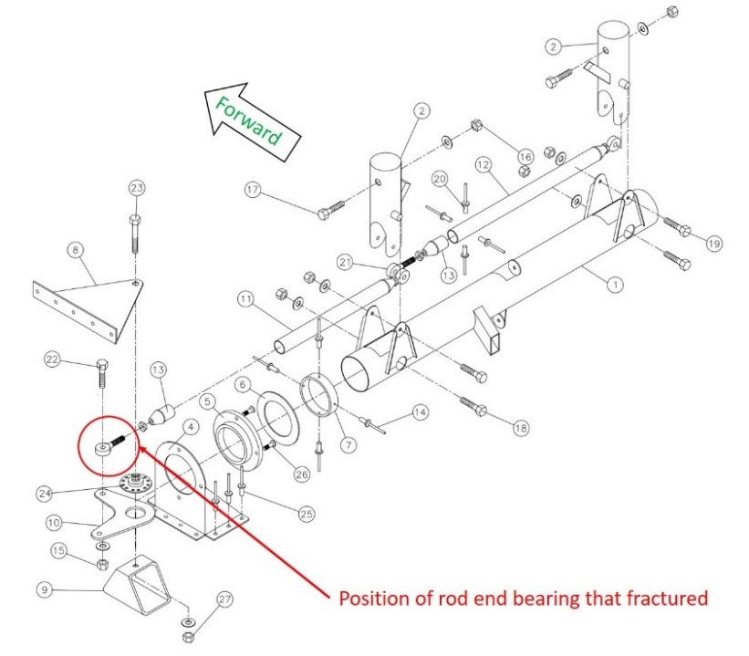
The rod end bearing that fractured was threaded into the outboard end of a push tube assembly (item 11, Figure 1) that is fabricated by the aircraft kit builder. This push tube assembly transfers aileron control input to the bell crank (item 10, Figure 1) mounted on the left, outboard side of the control column assembly.
The Murphy kit flight control instructions identify the rod end bearings as part number HM‑4M; however, the rod end bearings submitted to the TSB were all labeled as part number MM‑4M.
Part number HM‑4M is a rod end bearing manufactured by Heim,Footnote 1 as a precision aircraft series part. Part number MM‑4M is a general-purpose rod end bearing manufactured by Aurora Bearing Company (Aurora) that has undergone an additional inspection procedure. Although the Murphy kit identifies part number HM‑4M in this flight control application, Murphy has included rod end bearings supplied by a few different vendors, including Aurora, in their kits.
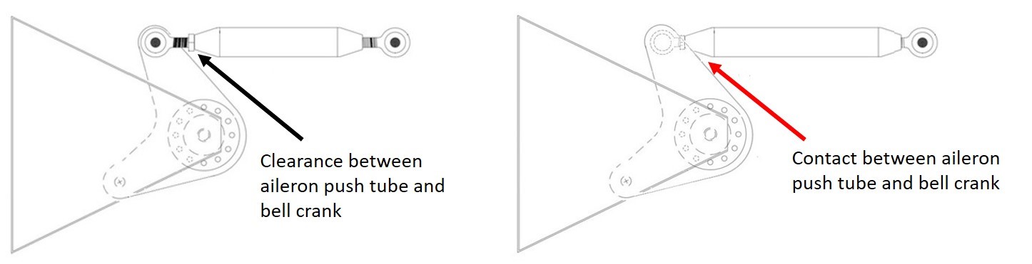
The Murphy kit instructions state that the tube material used to assemble the push tube must be cut to 3 inches in length; however, the tube material used to assemble the push tube submitted to the TSB had been cut to 4 inches in length. Therefore, the assembled push tube was longer than that specified in the instructions. As a result, the rod ends had to be threaded in further to achieve the aileron control system rigging (Figure 2).
The occurrence rod end bearing had been threaded completely into the aileron push tube assembly, which resulted in the jam nut contacting the bell crank when the push tube was moved outboard during full range aileron control inputs in that direction. In addition, the push tube rod end bearing had been mounted on the underside of the bell crank. This position was contrary to the manufacturer’s drawing, which shows the push tube rod mounted on top of the bell crank.
The rod end bearing fractured at the last root, outboard of the jam nut, due to the combination of the misalignment and the transverse forces encountered from this interference contact. In normal operation, the rod end bearing is loaded only along the push tube longitudinal axis.
The TSB procured 2 part number HM‑4M rod end bearings and 2 part number MM‑4M rod end bearings for testing. Both parts are identical in dimension, but vary in material composition and metallurgical characteristics. The TSB conducted mechanical testing, applying transverse loading on the rod end bearings that would have been similar to the forces encountered from the interference contact between the jam nut and bell crank. The test results indicated that when loaded transversely, the HM‑4M rod end bearings were approximately 20% stronger and, at the same time, significantly more ductile than the MM‑4M rod end bearings.
The TSB also examined another Murphy Rebel for comparison purposes. The tube material used for the push tube assembly of this comparison aircraft was cut to the correct length and was assembled and rigged correctly. Even with the push tube’s inboard and outboard rod end bearings threaded in equal amounts, as would be done during an ideal installation, there was very little clearance between the jam nut on the outboard rod end and the bell crank when aileron control output was applied to move the push tube outboard.
Deviation from Murphy Rebel kit assembly or rigging instructions can cause an aileron control geometry issue that may result in insufficient clearance between the bell crank and the jam nut, which could make the aircraft difficult to control as a result of jamming or rod end failure. In addition, using part number HM‑4M rod end bearings instead of part number MM‑4M rod end bearings may result in an installation that is more tolerant to occasional side or transverse loading situations.
The foregoing is provided for whatever follow-up action is deemed appropriate. The TSB would appreciate being advised of any action that is taken in this regard.
Yours sincerely,
Original signed by
Natacha Van Themsche
Director of Investigations – Air
Transportation Safety Board of Canada
Cc.
- President, Murphy Aircraft Manufacturing Ltd.
- Director, Aviation Safety Policy and Intelligence – Civil Aviation, Transport Canada
- President & CEO, Canadian Owners and Pilots Association
- President, The Recreational Aircraft Association Canada
- Vice President of Advocacy and Safety, Experimental Aircraft Association
- International Aviation Safety Specialist, National Transportation Safety Board
- Director, Accident Investigation and Prevention, Federal Aviation Administration