Main-track train derailment
Canadian National Railway Company
Freight train M30631-25
Mile 8.04, Pelletier Subdivision
Albertine Station, New Brunswick
The Transportation Safety Board of Canada (TSB) investigated this occurrence for the purpose of advancing transportation safety. It is not the function of the Board to assign fault or determine civil or criminal liability. This report is not created for use in the context of legal, disciplinary or other proceedings. See Ownership and use of content. Masculine pronouns and position titles may be used to signify all genders to comply with the Canadian Transportation Accident Investigation and Safety Board Act (S.C. 1989, c. 3).
Summary
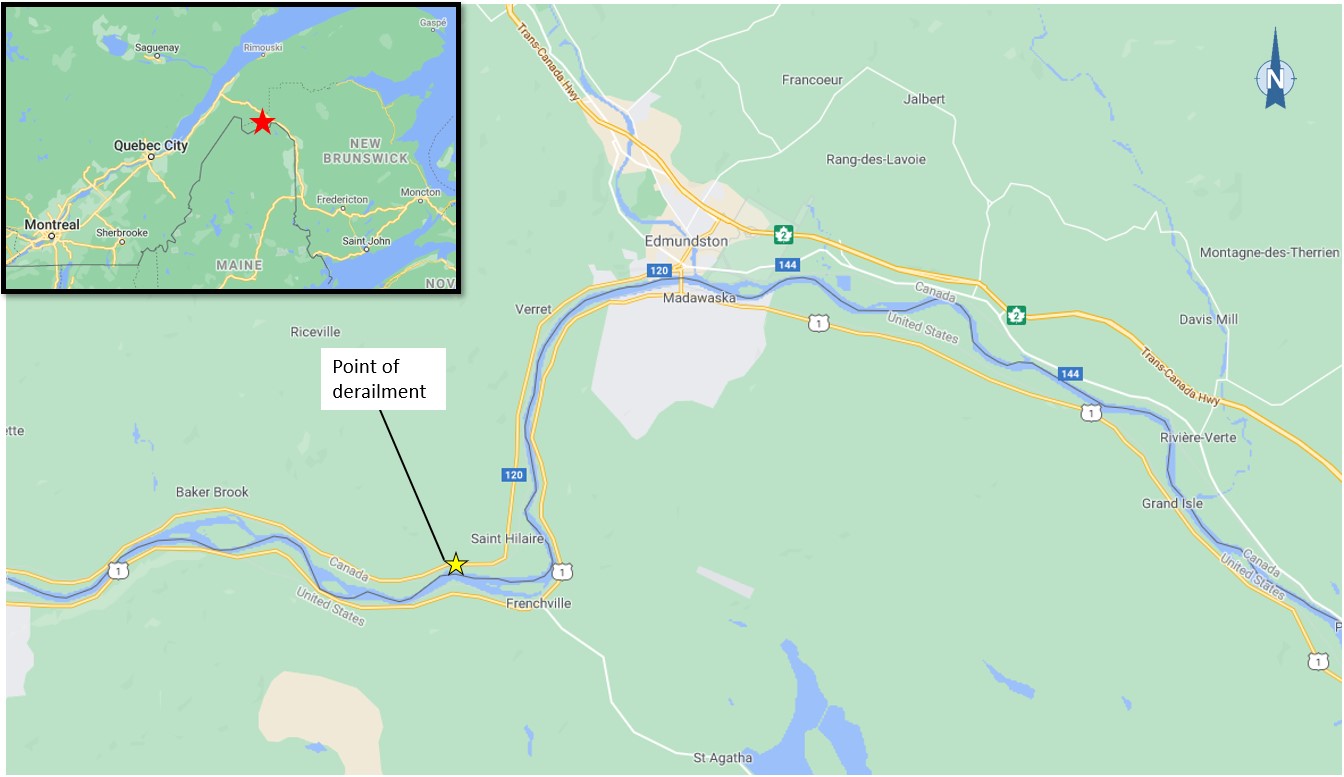
On 26 January 2021, at approximately 2030 Atlantic Standard Time, Canadian National Railway Company freight train M30631-25 was proceeding eastward at 46 mph on the Pelletier Subdivision when a train-initiated emergency brake application occurred. Twenty-two cars were subsequently found derailed near Albertine Station, approximately 8 miles southwest of Edmundston, New Brunswick (Mile 8 of the Pelletier Subdivision). Eight of the derailed cars were carrying dangerous goods. There was no fire, and no dangerous goods were released. No injuries were reported.
1.0 Factual information
1.1 The occurrence
On 26 January 2021, Canadian National Railway Company (CN) train M30631-25 left the Joffre Yard in Lévis, Quebec, en route to Edmundston, New Brunswick. At approximately 2030,Footnote 1 while travelling eastward at 46 mph on the Pelletier Subdivision, a train-initiated emergency brake application occurred near Albertine Station, about 8 miles southwest of Edmundston (Figure 1). Upon inspection by the conductor, 22 cars were found derailed. Eight of the derailed cars were carrying dangerous goods.Footnote 2 There was no fire, and no dangerous goods were released. No injuries were reported.
The train was composed of 3 head-end locomotives (CN 2937, CN 8000, and CN 2512), 2 distributed power locomotives (CN 2163 and CN 2247) at positions 126 and 127 in the train consist, and 171 mixed freight cars. It was 11 786 feet long and weighed 17 787 tons.
The crew consisted of 1 locomotive engineer and 1 conductor. The 2 crew members were qualified for their respective positions, met fitness and rest standards, and were familiar with the subdivision.
At the time of the occurrence, the weather was clear and the ambient temperature in the area was about −7 °C.
1.2 Site examination
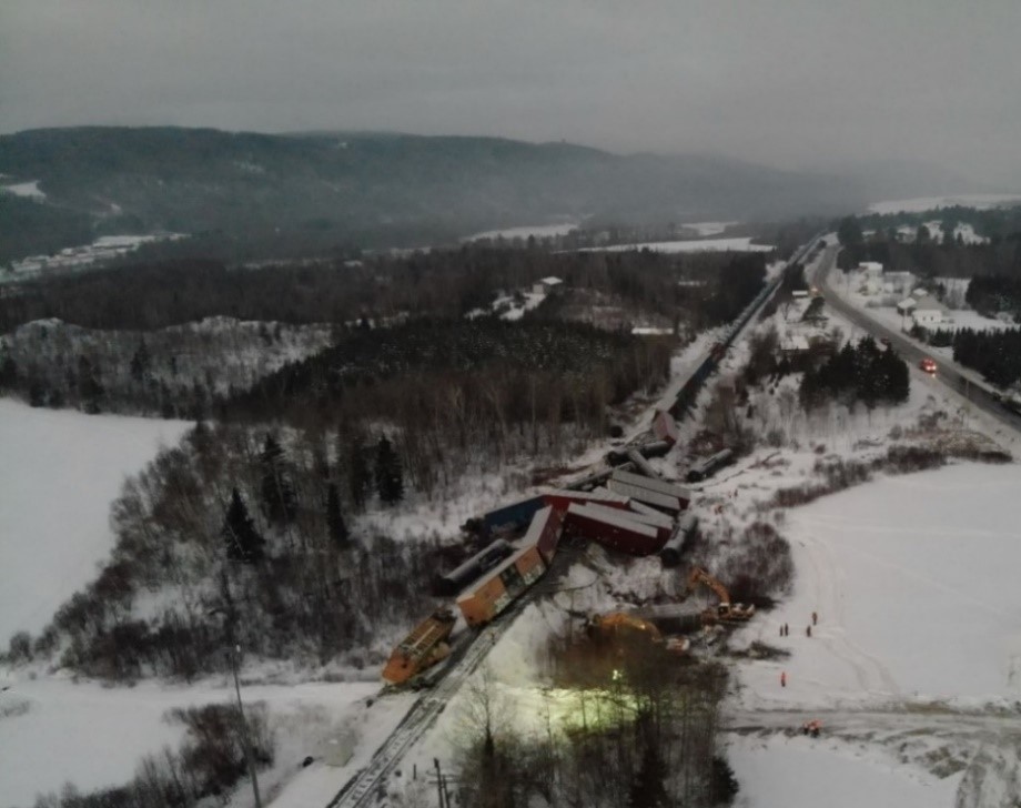
Twenty-two cars (cars 40 to 61 in the train consist) had derailed in an accordion fashion (Figure 2), destroying the track under the cars. The 40th car, CN 405766,Footnote 3 was the first car to derail.
The 39th car, IC 21013,Footnote 4 was still on the track. Its axles, trucks and brake beams had sustained minimal damage. The cross keyFootnote 5 retaining the coupler in the draft assemblyFootnote 6 at the leading end (A-end) of this car had sheared, leaving 3 small fragments (Figure 3) in the yoke.
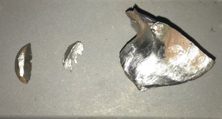
There was no major damage or wear to the yoke or to the centre sill. The couplerFootnote 7 had fallen and was found along the track, near the following car, CN 405766. The coupler had no excessive wear; however, fresh strike marks could be observed on its surface. The end-of-car cushioning device (EOCCD) was found to be in good condition and operating normally.
Three fragments of the failed A-end cross key, along with the trailing end (B-end) cross key from car IC 21013 were recovered from the occurrence site and sent to the TSB Engineering Laboratory for further examination.
1.3 Response to the occurrence
Several organizations responded to the occurrence, including the local fire department, CN, the Royal Canadian Mounted Police, the New Brunswick Emergency Measures Organization, and Transport Canada.
During the response operation, the 8 derailed cars containing dangerous goods were emptied, which involved transloading the contents of the 3 loaded cars and flaring the remaining residue in all 8 cars. During this process, residents located within a 700-metre radius of the occurrence site were given the choice to evacuate or shelter in their homes as a precaution.Footnote 8 One household chose to evacuate.
Route 120 was closed to the public for approximately 5 days while crews restored the track.
1.4 Recorded information
The lead locomotive was equipped with a locomotive event recorder and a forward-facing camera; a review of the data from this equipment did not reveal train handling or track anomalies.
1.5 Subdivision information
The Pelletier Subdivision runs between Mile 0.0 at Edmundston and Mile 86.9 at St. Andre Junction, Quebec, where it joins the CN Montmagny Subdivision. In the area of the derailment, the track is maintained as a class 3 track according to the Transport Canada–approved Rules Respecting Track Safety and the speed limit is 55 mph.
Train movements are controlled by the centralized traffic control system, as authorized by the Canadian Rail Operating Rules, and dispatched by a rail traffic controller located in Edmonton, Alberta.
1.6 Rail car draft assemblies
Rail cars are equipped on each end with a draft assembly (Figure 4). A draft assembly can contain either a standard draft gear, which absorbs impacts through mechanical means, or, as in this occurrence, an EOCCD, which absorbs impacts through a hydraulic system. The EOCCD draft assembly components typically have an extended range of movement versus the traditional mechanical style. This increased travel helps dampen impacts but in turn creates more slack in the train.
When a train is in motion, in-train forcesFootnote 9 are transmitted throughout the train by way of these draft assemblies. These forces are first applied to the knuckle and are transmitted through the other assembly components, including the cross key, into the draft gear, which dampens them. Typically, the knuckle is the weakest component of the assembly and is designed to fail first in the presence of excessive draft forces. An in-service knuckle is expected to withstand up to 250 kipsFootnote 10 before failing.Footnote 11 The A-end knuckle of car IC 21013 did not fail in this occurrence.
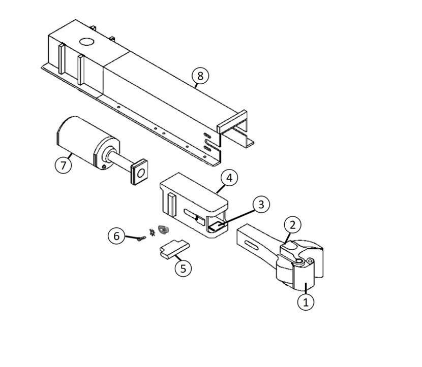
- Knuckle
- Coupler
- Coupler carrier wear plate
- Yoke
- Cross key
- Retaining hardware
- End-of-car cushioning device
- Centre sill
Within the draft assembly, the coupler carrier wear plate helps ensure that the coupler remains level and at the proper height. This steel or polymer wear plate is fitted to the yoke or striker, and the shank of the coupler rests upon it. Normal coupler movements can wear the plate, causing the coupler to sit lower and at an angle, which puts additional stresses on the cross key. In this occurrence, the coupler carrier wear plate on the A-end of IC 21013 was in place and did not show signs of excessive wear.
Cross keys in EOCCDs are a solid piece of forged metal and are designed to retain the coupler in the yoke as part of the draft assembly. They generally remain in service for many years, and are only replaced when they are worn beyond set limits (see Section 1.10) or develop a condemnable defect.
1.7 Effect of train length and weight on in-train forces
Train operations have changed over the past 25 years. Newer locomotives have improved dynamic braking capability and energy management systems; these locomotives, when distributed in the middle or at the end of trains, along with improved train marshalling and handling, have allowed railways to operate longer and heavier trains. Before the mid-1990s, an average mixed-manifest train in main-track service was about 5000 feet long and weighed 6000 to 7000 tons. In contrast, CN mixed-manifest trains in today’s operating environment have an average length of 8900 feet, but can be up to 12 000 feet long and can weigh as much as 18 000 tons. Long, heavy trains can generate significant buff and draft forces due to the slack action of the train. Cars equipped with EOCCDs contribute to these in-train forces due to the extended range of movement of their components. CN uses distributed locomotives with newer technologies and train marshalling in order to mitigate these in-train forces.
1.8 Train handling simulation
The TSB commissioned a simulation of train handling of the occurrence train to determine if there were any train handling or marshalling issues, and whether there were excessive in-train forces present leading up to the derailment.
The simulation did not identify any train handling issues.
Draft forces of approximately 85 kips were observed at the location of car IC 21013 at the time of train separation. This amount of force is well within expected limits of train operating parameters and draft assembly components.
1.9 Laboratory examination
1.9.1 Examination of the recovered fragments from the failed A-end cross key
The TSB laboratory examined the fragments from the failed A-end cross key recovered from car IC 21013. Given the small size of the fragments, the examination focused on the largest fragment, which was found lodged within the yoke.
The failed cross key was originally designed around 2006 and manufactured approximately 4 years before the occurrence. A metallurgical examination of the fragment determined that both its microstructure and chemical composition met the material specifications indicated in the manufacturer’s engineering drawings.Footnote 12 There were no indications of metallurgical anomalies.
The examined fragment had a significant amount of plastic deformation. Due to the small size of the fragment and the extent of the damage it had sustained, the mode of failure of the cross key could not be ascertained.
1.9.2 Examination of the other cross keys
A visual examination of the B-end cross key of car IC 21013 revealed cracks and signs of plastic deformation. In an effort to better understand the failure mechanism, the TSB collected 9 more cracked cross keys of similar style and vintage that had been bad ordered by CN as part of a preventive inspection program. The B-end cross key and these 9 other cross keys were examined, subjected to hardness testing, and visually inspected.
Hardness testing using the Brinell method confirmed that the material hardness of all 10 cross keys was within requirements.Footnote 13
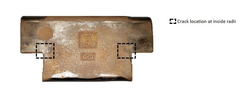
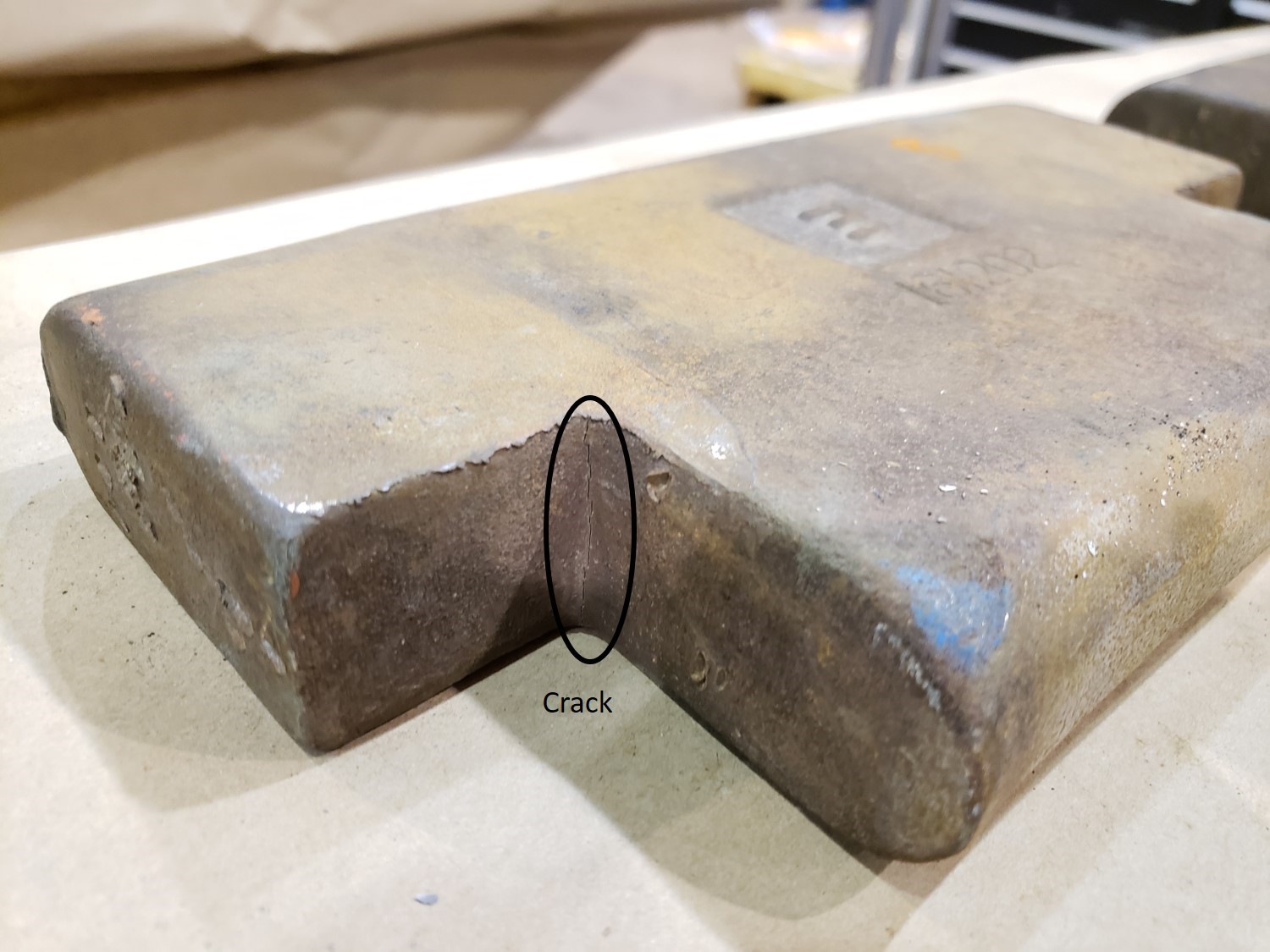
Each of the 10 cross keys was measured and found to meet the drawing specifications. Through visual inspection, it was noted that all 10 cross keys had at least one crack located at one of the inside radii (Figure 5). Eight cross keys had cracks at both inside radii. In all cases, the cracks were through the thickness of the cross key and originated at the inside radii of the keys (Figure 6).
The laboratory examination determined that cracks originating at one or both of the radii were a result of fatigue. Given the sharp angle of the inside radii, there would be higher residual stress in these areas. Furthermore, all examined cross keys had a significant amount of plastic deformation.
In order to further examine the cracks, 3 of the cross keys were sectioned adjacent to the crack tip and opened. Metallurgical testing of these cross keys indicated that the microstructure met the material composition specified on the relevant engineering drawing. Fractography performed on the same 3 cross keys showed beach marks on the fracture surfaces, consistent with fatigue crack propagation.
1.10 In-service inspection requirements for cross keys
There is no prescribed interval for the inspection of cross keys installed on cars equipped with EOCCDs. Because EOCCDs have retaining hardware to ensure that they remain in position, the cross keys are not easily accessible for inspection in the field. Consequently, they are usually only inspected when work takes place on the draft assembly.
EOCCDs have been used in the railway industry since the 1950s and they have been in widespread service since the 1990s. In January 2020, the Association of American Railroads (AAR) amended Rule 59, Cushioned Underframe Devices, of the Field Manual of the AAR Interchange Rules. This amendment changed the wear allowance for cross keys from 5/16 inch to ¼ inch. In addition, this amendment also required that cracked cross keys identified at any time be replaced.
1.11 TSB laboratory reports
The TSB completed the following laboratory report in support of this investigation:
- LP017/2021 – Cross Key Examination
2.0 Analysis
Neither the actions of the train crew nor the condition of the track contributed to the occurrence. The analysis will focus on the metallurgical analysis of the failed cross key and in-train forces.
2.1 The occurrence
While proceeding eastward on the Pelletier Subdivision, Canadian National Railway Company (CN) train M30631-25 derailed. Fresh strike marks on the coupler that had fallen from the leading end (A-end) of car IC 21013 indicate that the 40th car in the consist, CN 405766, struck the coupler, leading to the derailment. An emergency brake application was initiated when the air hose between the 38th and 39th car separated during the derailment.
Finding as to causes and contributing factors
The train derailed when car CN 405766 struck a coupler that had fallen from the leading end of the preceding car, IC 21013. The coupler fell after the cross key that was retaining it in place failed in service.
The draft assembly components on the A-end of car IC 21013, including the coupler carrier wear plate, did not show any signs of excessive wear or major damage, which indicates that they likely did not contribute to the failure of the cross key.
2.2 Examination of failed components
The mode of failure of the A-end cross key of car IC 21013 could not be ascertained due to the small size of the fragments and the extent of the damage it had sustained. The laboratory examination of the B-end cross key of car IC 21013 and of 9 additional cracked cross keys of similar style and vintage that were bad ordered by CN determined that the cracks identified at the inside radii on all the cross keys were due to fatigue. In addition, following the derailment, inspections by CN revealed 408 cars with defective cross keys out of 604 cars inspected.
The plastic deformation observed in the cross keys suggests that their yield strength was insufficient to withstand the loading stresses applied during service. Loading beyond yield in compressionFootnote 14 allows for a localized residual tensile stress in the area of the radii when the compressive load is removed. This stress allows for progressive crack propagation each time a cross key is loaded and unloaded. Given the material met the specifications and the part experienced plastic deformation, it is likely that there are design limitations with either the specified material or the geometry of the part, including an incorrect radius causing localized stress risers.
Finding as to causes and contributing factors
The failed cross key had developed fatigue cracks at the inside radii, which likely occurred over its 4 years of service before the derailment.
Finding as to causes and contributing factors
It is likely that the design of the specific cross key used in the end-of-car cushioning device on the occurrence car, including material specifications, geometry, and/or dimensions, contributed to the initiation and propagation of the fatigue cracks.
2.3 In-service cross keys
When cars are equipped with end-of-car cushioning devices (EOCCDs), the additional longitudinal movement permitted by these devices increases slack action, which contributes to increased in-train forces. Mitigation efforts such as the use of distributed power locomotives, dynamic braking, and train marshalling allow railway companies to manage these in-train forces. However, the operation of longer and heavier trains without adequate mitigation can increase in-train forces and, consequently, the risk of component failure.
A cross key is a critical component as it retains the coupler in place. An in-service failure of a cross key has the potential to lead to a derailment, as demonstrated in this occurrence. Generally, cross key failures are unlikely during normal train operations because the knuckle is designed to fail first in the presence of excessive buff or draft forces. A cross key with compromised structural integrity may experience an in-service failure if it has been subjected to in-train forces.
Cross keys should meet the demands of their operating environment. In order to ensure that cross keys remain in serviceable condition, it may be necessary to periodically assess their fitness for service. In January 2020, the Association of American Railroads (AAR) amended the wear allowance for cross keys from 5/16 inch to ¼ inch and specified that cracked cross keys identified at any time require replacement. There is no prescribed interval for the inspection of cross keys.
Finding as to risk
If the design of critical components such as cross keys is not reassessed based on changes in railway operating conditions and their inspection frequency is not adjusted accordingly, these components could fail in service, increasing the risk of derailment.
3.0 Findings
3.1 Findings as to causes and contributing factors
These are conditions, acts or safety deficiencies that were found to have caused or contributed to this occurrence.
- The train derailed when car CN 405766 struck a coupler that had fallen from the leading end of the preceding car, IC 21013. The coupler fell after the cross key that was retaining it in place failed in service.
- The failed cross key had developed fatigue cracks at the inside radii, which likely occurred over its 4 years of service before the derailment.
- It is likely that the design of the specific cross key used in the end-of-car cushioning device on the occurrence car, including material specifications, geometry, and/or dimensions, contributed to the initiation and propagation of the fatigue cracks.
3.2 Findings as to risk
These are conditions, unsafe acts or safety deficiencies that were found not to be a factor in this occurrence but could have adverse consequences in future occurrences.
- If the design of critical components such as cross keys is not reassessed based on changes in railway operating conditions and their inspection frequency is not adjusted accordingly, these components could fail in service, increasing the risk of derailment.
4.0 Safety action
4.1 Safety action taken
4.1.1 Canadian National Railway Company
Following the occurrence, Canadian National Railway Company (CN) initiated a proactive cross key inspection program for cars having the same manufacturer, draft gear design and manufacturing timeframe as the occurrence car. Of the 604 cars inspected, 408 were found to have a defective cross key.
4.1.2 Component manufacturer
The component manufacturer revised the cross key geometry by increasing the radius in the area in which cracking had occurred in order to lower stresses and improve performance. The updated cross keys are currently undergoing service trials.
This report concludes the Transportation Safety Board of Canada’s investigation into this occurrence. The Board authorized the release of this report on . It was officially released on .