Main-track derailment
Canadian Pacific Railway
Freight train 374-230
Mile 23.40, Crowsnest Subdivision
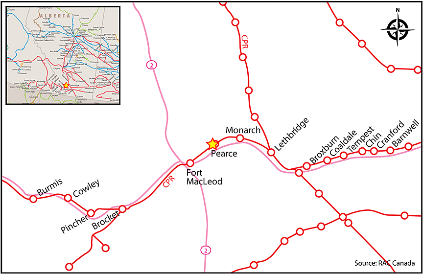
Pearce, Alberta
The Transportation Safety Board of Canada (TSB) investigated this occurrence for the purpose of advancing transportation safety. It is not the function of the Board to assign fault or determine civil or criminal liability. This report is not created for use in the context of legal, disciplinary or other proceedings. See Ownership and use of content. Masculine pronouns and position titles may be used to signify all genders to comply with the Canadian Transportation Accident Investigation and Safety Board Act (S.C. 1989, c. 3).
Summary
On 06 November 2014, at about 0115 Mountain Standard Time, eastbound Canadian Pacific Railway freight train 374-230 derailed 17 empty covered hopper cars at Mile 23.40 of the Crowsnest Subdivision near Pearce, Alberta. About 1000 feet of the main track was damaged and an additional 600 feet of the main track and of an adjacent storage track was destroyed. Two empty gondola cars in the storage track were struck by the derailing train, resulting in their derailment. There were no injuries.
Le présent rapport est également disponible en français.
Factual information
The accident
On 06 November 2014, at about 0115,Footnote 1 Canadian Pacific Railway (CP) freight train 374-230 (the train) was proceeding eastward at approximately 40 mph, when the tail-end 17 cars derailed at Mile 23.40 of the Crowsnest Subdivision, near Pearce, Alberta (Figure 1).
The conventional trainFootnote 2 consisted of 2 head-end, 6 axle, 4300 horsepower General Electric locomotives and 81 empty covered hopper cars. The train was 4922 feet long and weighed 2528 tons. The train originated in Eastport, Idaho, had crossed into Canada at Kingsgate, British Columbia; it was to continue on to North Portal, Saskatchewan, where it would cross back into the United States en route to its final destination of Glenwood, Minnesota.
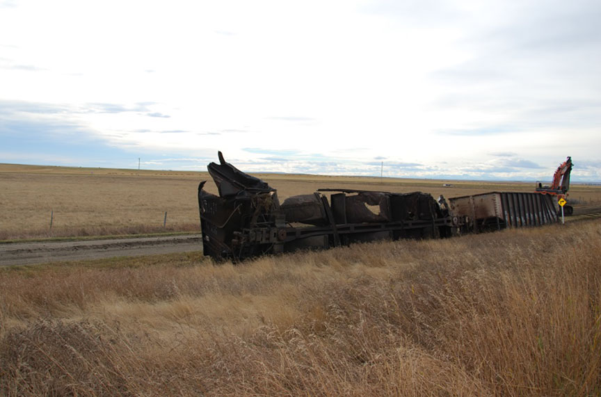
Just before the derailment, a train-initiated emergency brake application occurred. After making the necessary emergency broadcast and notifying the rail traffic controller (RTC) in Calgary, the conductor performed an inspection of the train and determined that the tail-end 17 cars had derailed in 2 groups. The last 10 cars had derailed at the west storage track switch at Pearce (Figure 2). Some of these derailed cars struck 2 empty gondola cars that had been stored in the storage track adjacent to the main track (Photo 2). The other 7 derailed cars were dragged about 1000 feet east and remained upright.
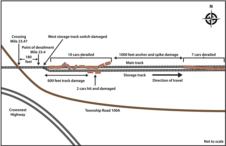
In the vicinity of the group of 10 derailed cars, approximately 600 feet of the main track and the storage track was destroyed. In addition, approximately 1000 feet of main track was damaged (i.e., tie, anchor, and spike damage) between the 2 groups of derailed cars.
The point of derailment was determined to be a broken rail near a joint in the south rail located approximately 180 feet east of the crossing at Township Road 100A (Mile 23.47) (Figure 2).
The train crew was composed of a locomotive engineer and a conductor. Both crew members were qualified for their respective positions, met rest and fitness standards, and were familiar with the subdivision.
There were no injuries.
At the time of the occurrence, the weather was clear and calm with a temperature of 8 °C.
Crowsnest Subdivision
The Crowsnest Subdivision is part of CP’s southern coal route between Medicine Hat, Alberta, and Fort Steele, British Columbia. Movements over this subdivision are governed by the occupancy control system (OCS), as authorized by the Canadian Rail Operating Rules, and supervised by a rail traffic controller located in Calgary, Alberta. In the vicinity of the derailment, the maximum authorised speed for freight trains was 45 mph. The track at this location was Class 4 track as defined by the Transport Canada-approved Rules Respecting Track Safety (TSR).
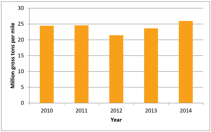
Traffic on the Crowsnest Subdivision was composed primarily of grain trains and coal trains, totalling about 26 million gross tons per mile (MGT per mile) in 2014 (Figure 3).
Being an OCS subdivision (i.e., “dark territory”), the Crowsnest Subdivision does not have a signalling system. Signal systems, although not specifically designed to do so, can provide some protection from broken rails when track circuit continuity is disrupted because all signals in the block turn to their most restrictive indication. This type of protection is not available on non-signalled track.
Recorded information
The data from the locomotive event recorder on the trailing locomotive was reviewed. The final movement started approximately 45 minutes before the derailment, when the train accelerated from rest up to 10 mph in about 30 seconds. Moderate throttle ranging from idle to throttle notch 4 was used. Once the train reached 10 mph, the throttle was advanced to notch 8 in about 90 seconds to accelerate the train up to 40 mph. Throttle modulation was then used to handle the train for the next 40 minutes. Speed varied between about 15 mph to 45 mph during this period. The train-initiated emergency brake application occurred at 0109 when the train was travelling at about 40 mph with the throttle in notch 2.
Particulars of the track
The track in the area of the derailment is tangent on an eastward ascending grade of 0.2%. The track structure was primarily 115 pound continuous welded rail (CWR) manufactured by Algoma in 1967 set on double shoulder tie plates, fastened to the ties using 3 spikes per plate and box anchored every tie. Although the ties in the vicinity of the point of derailment (POD) were in compliance with applicable Transport Canada standards for tie conditions, they were in poor condition, with many ties plate-cut and/or split. The track shoulder was between 18 to 24 inches wide and the tie cribs were full of ballast. The ballast was in fair condition.
Prior to the derailment, in 2013 and 2014, CP’s track evaluation car had conducted 6 track geometry measurement tests through the derailment area. During these tests, the majority of the identified defects, situated at or near the POD, were priorityFootnote 3 wide-gauge defects, surface defects, alignment defects, and surface runoff defects. For the track geometry test conducted on 15 May 2014, 15 priority defects and 2 near-urgent defects were identified. These defects had been corrected by the time the next test was conducted on 25 July 2014.
In the vicinity of the occurrence, a number of Digital Track Notebook (DTN) inspectionsFootnote 4 had been conducted in October 2014, and several track defects (T.D.) involving rail joints were identified (Table 1).
| Date | Location | Track defect |
|---|---|---|
| October 3, 2014 | Mile 34.8 | No track defects recorded in DTN |
| October 6, 2014 | Mile 34.8 | No track defects recorded in DTN |
| October 7, 2014 | Mile 21.1 | T.D.5.3* |
| October 10, 2014 | Mile 34.8 | T.D.5.7** |
| October 10, 2014 | Mile 50.02 | T.D.5.7 |
| October 13, 2014 | Mile 25.7 | No track defects recorded in DTN |
| October 14, 2014 | Mile 25.7 | T.D.5.7 |
| October 14, 2014 | Mile 26.02 | T.D.5.7 |
| October 16, 2014 | Mile 28.13 | No track defects recorded in DTN |
| October 17, 2014 | Mile 28.13 | T.D.5.3 |
| October 21, 2014 | Mile 16.1 | T.D.5.3 |
| October 27, 2014 | Mile 12.2 | No track defects recorded in DTN |
| October 31, 2014 | Mile 12.2 | T.D.5.5*** |
| * T.D.5.3 – Cracked or broken joint bar ** T.D.5.7 – Less than 2 bolts per rail at joint in CWR *** T.D.5.5 – Less than 2 bolts per rail at joint for conventional jointed rail in Class 2 to 5 track |
||
The most recent regular track inspection had been conducted on 04 November 2014. No defects were noted in the vicinity of the derailment.
The rail in many of the curves on the Crowsnest Subdivision was CWR, but much of the tangent track was jointed rail (i.e., 1960s vintage Algoma rail). The jointed rail between Mile 42.1 and Mile 70.7 had been replaced with CWR. Installation of an additional 3.46 miles of CWR to replace joints between the POD at Mile 23.4 and Mile 42.1 was scheduled for 2016.
Rail grinding
Rail grinding is a maintenance procedure used to control surface damage on the rail, including corrugations, shelling, head checking, and spalling.Footnote 5 Rail grinding is also used to restore the contact geometry between the wheel and the rail by ensuring the correct rail head profile. In doing so, the wheel/rail contact position can be moved across the rail head to a location that minimizes contact stresses. By adjusting the contact geometry, the initiation of deep-seated shell defects such as detail fracturesFootnote 6 at the upper gauge corner can be prevented. Rail grinding can also slow down the initiation and growth of small, deep-seated shell defects and can therefore extend the rail’s service life.
Rail grinding is considered to be the primary defence against internal defect initiation and propagation and is critical for maintaining the rail surface in good condition which will allow optimal defect detection. Rail grinding requirements and grinding schedules are normally based on the traffic volume (i.e., million gross tons of traffic over the territory), the rate of the growth of defects, the rail surface condition, and the need to maintain the preferred rail profile.
Inadequate rail support accelerates the growth of rail defects and the overall deterioration of the track structure, reducing the effectiveness of rail grinding programs.
Rail grinding had been conducted in the vicinity of the derailment prior to the occurrence, on 09 April and 26 September 2014.
Rail testing
Ultrasonic testing (UT) is the primary method for detecting internal rail defects to proactively manage the risk of rail failures. In recent years, improvements have been made to this rail testing technology, including additional probes at different angles, enhancements to the defect-recognition software, and enhancements to the operator/system interface. UT can be a reliable and economical approach to rail flaw testing. However, its ability to identify defects is dependent on the size of the defect and the orientation of the transverse portion of the defect.
The UT results can be affected if there is contamination on the rail surface or if rail head checking, spalling and shelling is present on the rail surface. Such conditions can inhibit the transmission of ultrasonic signals into the rail head which can mask the detection of internal defects. Since 2005, the Transportation Safety Board of Canada has investigated 7 other derailments involving rail breaks due to undetected rail defects (Appendix A). These occurrences included situations when rail flaw testing had been conducted shortly before the accident. However, the test results had been affected by poor rail surface conditions, the defect size was initially too small or the orientation of the defect had prevented detection.
Rail flaw testing on the Crowsnest Subdivision was conducted by Herzog.Footnote 7 The Herzog rail flaw detector vehicles are equipped with an undercarriage test platform containing 2 fluid filled roller search unit wheels that are each equipped with seven transducers (for a total of 14 transducers on each rail). The transducers send sound energy into the rail at different angles to detect vertical defects and transverse defects. The transmission of this ultrasonic energy from the transducers into the rail is facilitated by a liquid couplant.
Prior to the derailment, the Crowsnest Subdivision had been tested for rail defects in February 2014, March 2014, May 2014, July 2014, and September 2014. Rail flaw detection was also scheduled for November 2014 and December 2014. The TSR requirement to test for rail defects for Class 4 tracks with 15 - 35 MGT per mile is at least 3 times annually.
In the vicinity of the derailment, during the most recent test conducted on 19 September, 2 rail defects were identified (Table 2).
| Mile | Defect | Rail |
|---|---|---|
| 23.4 | Horizontal split head | 1971 Sydney Rail |
| 26.8 | Horizontal split head | 1974 Algoma |
Shortly after this occurrence (on 09 November 2014), there was a second derailmentFootnote 8 on the Crowsnest Subdivision at Mile 70.7. CP then conducted a rail test on an emergency basis over the subdivision and 22 rail defects were identified (Table 3). Remedial action was taken by CP to correct the defects identified in the emergency inspection.
| Mile | Defect | Rail |
|---|---|---|
| 10.3 | Horizontal split head | Frog |
| 12.3 | Defective plant weld | 1974 Algoma |
| 16.1 | Transverse fissure | 1977 Algoma |
| 16.7 | Defective plant weld | 1977 Algoma |
| 16.8 | Defective plant weld | 1977 Algoma |
| 17.7 | Defective field weld | 1975 Algoma |
| 19.9 | Shelled, spalled, corrugated | 1976 Algoma |
| 28.2 | Defective plant weld | 1968 Algoma |
| 28.4 | Defective plant weld | 1968 Algoma |
| 30.8 | Defective plant weld | 1963 Algoma |
| 42.3 | Transverse defect | 1976 Algoma |
| 52.9 | Defective plant weld | 2012 Nippon |
| 69.6 | Shelled, spalled, corrugated | 1982 Algoma |
| 71.5 | Defective plant weld | 1971 Algoma |
| 74.5 | Defective plant weld | 1969 Algoma |
| 77.5 | Bolt hole joint | 1970 Algoma |
| 77.8 | Bolt hole joint | 1970 Algoma |
| 80.5 | Defective plant weld | 1971 Algoma |
| 89.2 | Crushed rail head > ¼ inch | 1981 Algoma |
| 99.4 | Transverse defect | 1981 Algoma |
| 99.4 | Crushed rail head > ¼ inch | 1981 Algoma |
| 99.6 | Crushed rail head | 1981 Algoma |
CP rail testing frequency and analysis
CP reviewed the detected and in-service defects to determine root cause. The identification of patterns was being performed on an ongoing basis. Where there were defects, and particularly where there was an increase in frequency or a pattern of failures, the incidents were reviewed. In many cases, laboratory tests were conducted and an assessment of the required corrective action was made.
CP used several data metrics to determine rail testing frequencies, including tonnage, service failures, detected defects and defect size (growth between tests). CP also considered other risk factors such as whether the territory was signalized or dark. The testing cycles were dynamic and were adjusted if any combination of these factors changed.
CP performed weekly audits on all rail flaw equipment operating on the system. These audits reviewed the equipment settings to ensure compliance with specifications. Previous test data was compared if large numbers of defects were detected on a test.
CP also conducted in-service rail failure investigations for failures that occurred within 30 days of a rail flaw detection (RFD) test or that exhibited defects that were considered to be of a “detectable” nature. This information was used for trending with a particular vendor or RFD operator.
Rail transverse detail defects
A detail fracture is classed within a group of fatigue defects referred to as transverse detail defects (TDD). This type of defect is characterized as a progressive fracture of the rail starting from a longitudinal separation close to the running surface, or from shelling usually starting at the upper gauge corner and spreading transversely through the rail head perpendicular to the running surface of the rail.
Shelling is a fatigue defect, which is caused by stresses generated during the passage of wheels. Once initiated, shelling can continue to grow longitudinally along the rail. From a longitudinal shell, transverse cracks can split or branch off and then grow vertically to form detail fractures. However, most shells do not turn into detail fractures. The mechanism by which these defects branch and start to grow in a transverse direction is unknown.
Identification of TDDs can be difficult as the fracture is not often exposed. TDD fractures typically display growth rings or striations that indicate the progressive growth of the detail fracture with each fatigue cycle. While UT can locate a TDD before it fails, the testing does have limitations. For example, as the longitudinal separation or seam of the fracture is not often exposed, positive identification cannot normally be made until the rail is broken. Failure frequently occurs before the defect becomes visible and will generally result in a complete break of the rail.
The size of a detail fracture is commonly recorded as the percentage of the cross sectional head area of the rail. As the size of the detail fracture increases, less of the head area is available to support the load. Once the defect reaches a critical size, the remaining rail head area would no longer be able support the load, resulting in sudden and complete failure of the rail. This situation is accelerated when the rail head area has already been reduced due to wear.
Non-conformal wheel-rail contact geometry (e.g., a wheel flange in point or line contact with a rail head) and sliding friction will create stresses that can cause rail surface plastic flow (creep) on the rail head. Plastic flow can lead to gauge corner collapse, especially if there are deep-seated shells. Plastic flow can also lead to internal inclusions acting as nuclei for defect growth, including transverse defects such as detail fractures.
The growth rate of a TDD can be highly inconsistent and unpredictable. For example, the growth rate can initially be slow until the defect reaches 10% to 20% in size. Then, the growth rate can be rapid, leading to sudden fracture through the web and the base of the rail. Moreover, a sudden, complete failure can occur in defects of any size.Footnote 9 Research has shown that the average growth rate of a detail fracture defect can exceed 5% of the cross-sectional area of the rail head for every 1 million gross tons of train traffic.Footnote 10
TDDs typically develop in rails that are at or near their fatigue limit. Rail fatigue lifeFootnote 11 depends on a number of factors including accumulated tonnage, location (i.e., curve or tangent track), cleanliness and grade of the steel, the condition of the rail support system, and residual stressesFootnote 12 within the rail. Maintaining the appropriate rail profile through grinding and proper friction management (lubrication) also directly affects rail life. Rail fatigue life is difficult to predict; however, with increased testing, inspections and rail relay programs, fatigued rails can normally be identified and removed before they reach their fatigue life.
Fatigue defects such as TDDs are considered more severe than rail wear defects such as battered rail ends and curve worn rail. Service life for rail can be defined by wear or fatigue limits, whichever occurs first. Rail relay programs are typically implemented to replace rail that is close to its wear life and/or fatigue life based on defect type and frequency.
Previous trains through derailment area
The 3 trains (trains 469-04, 462-04, and 463-04) that had operated through the area of the POD immediately before the occurrence train each weighed at least 6900 tons; indeed, the last one through the derailment area before the occurrence train, westbound train 463-04, weighed 8753 tons. None of the 3 trains had registered wheel impacts that were higher than normal.
Laboratory analysis of broken rail
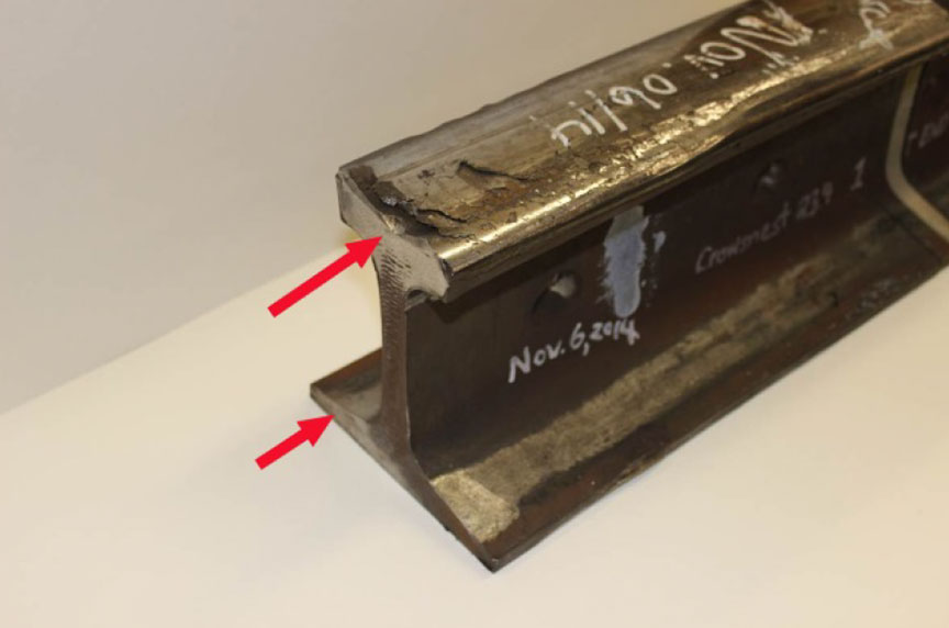
Two pieces of broken rail (Photo 3) were recovered from the derailment site and were sent to the TSB Engineering Laboratory for detailed examination.
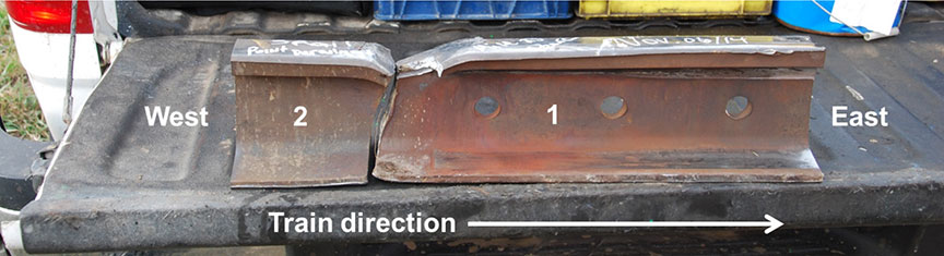
Rail piece No. 1 had a transverse fracture at its west end and a manufactured cut at the east end. The 3 holes in the web indicate that this piece was the west end of a joint. The east end of rail piece No. 2 and the west end of rail piece No. 1 were mating fracture faces.
The following was also determined:
- The fracture had started in the head of the rail about 2 inches from the end of the joint.
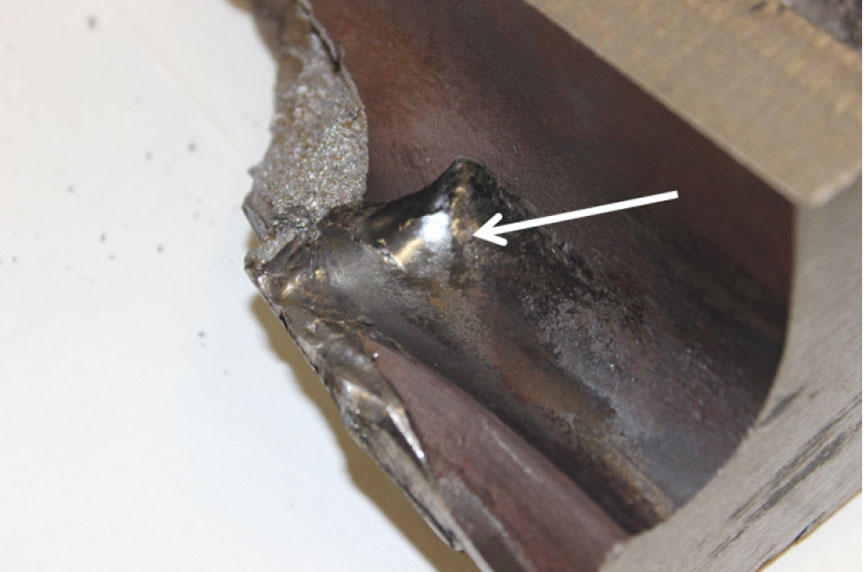
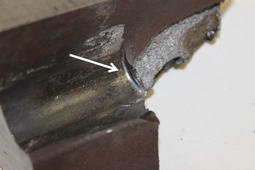
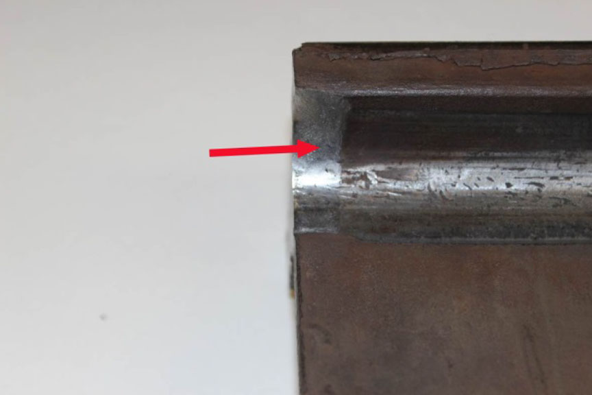
- The fillet under the head on rail piece No. 1 had been extensively deformed by the ends of the joint bars (photos 4 and 5).
- Both rail pieces had 7/16 inches of vertical head wear. The wear on the gauge side and the field side was between +1/16 inch and +3/16 inch. For both rail pieces, the variance was due to a lip that had formed on the gauge side of the rail and to the deformation on the field side (Figure 4). As the rail head wore down, it also spread out on the gauge and field sides.
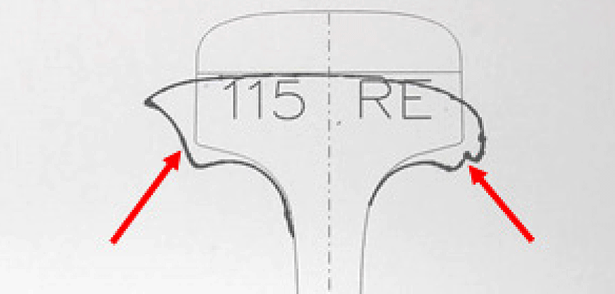
- As noted in Appendix 6 of CP’s Red Book of Track Requirements, the vertical head wear limit for 115-lb RE rail (with zero flange wear) was 11/16 inch. The rails had not yet reached the limit at which worn rail must be removed from track.
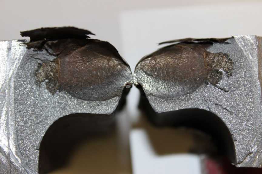
- Wheel impact damage was present on the surfaces of both rail pieces. This impact damage was more severe on rail piece No. 1. This suggests that the rail had been broken before the occurrence and that wheels had been impacting the fracture from both directions.
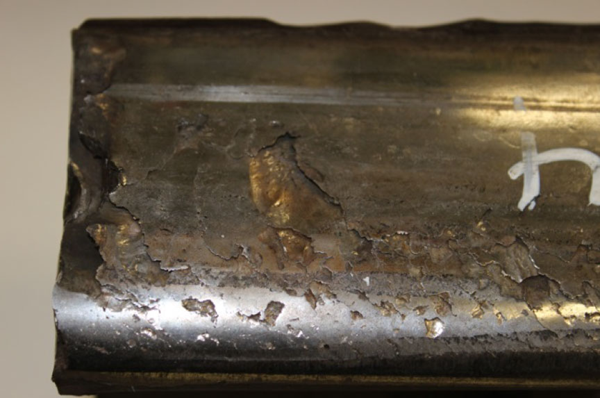
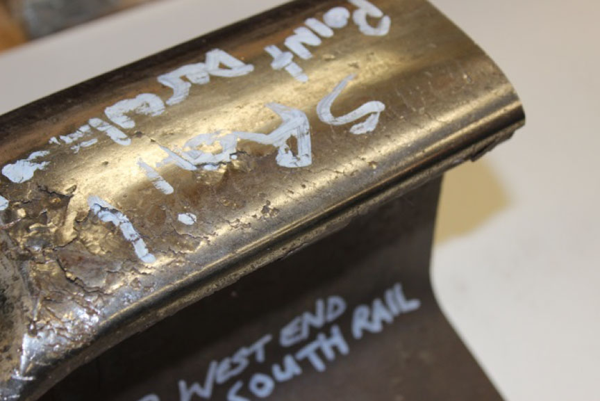
- Head checks and shelling were observed on the gauge corner on both rail pieces (photos 6 and 7).
- On rail piece No.1 near the manufactured cut (east end), there was a distinct rubbing or fretting mark on the base of the rail (Photo 8) and on the fillet under the rail head on the gauge side (Photo 9). These rubbing marks suggest that the west end of the joint bar on the gauge side had broken and that the rubbing marks were likely made by the top and bottom piece of the east end of the joint bar. The head and base areas of the east end of rail piece No. 1 also exhibited polishing suggesting the rail had been rubbing against the mating rail (Photo 10).
As the fracture features in the rail head had been obliterated by post-separation impact damage, additional UT testing was necessary to determine if there were any transverse defects in the rails. The following was found:
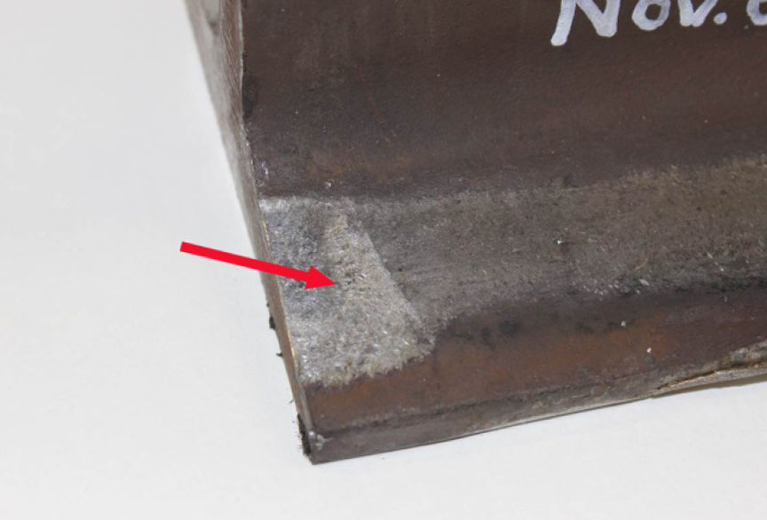
- A crack indication was present about 5 ¼ inches from the cut end of rail piece No. 2. This rail piece was sectioned further, allowing the suspected crack to be opened through laboratory induced overstress. The transverse defect is shown in Photo 11.
- The crack had initiated from a head check on the gauge side of the head and had progressed in fatigue.
- After turning down into the head, the transverse crack had progressed to approximately 17% of the current head area.
The laboratory examination and analysis also found the following:
- The rail broke in transverse overstress approximately 2 inches from the end of a joint bar.
- The impact damage observed at the fracture location suggested that the rail was most likely broken for some time prior to the occurrence.
- The gauge side of the rail head exhibited head checks and shelling which are known to lead to the formation of transverse defects. It was not possible to determine if the rail fracture had initiated from a transverse defect due to the extensive impact damage sustained by the fracture surface in the rail head.
- Rubbing marks indicated that there was significant play in the joint and that the gauge side joint bar may have been broken for some time. It could not be determined if this was contributory to the rail fracture.
- The gauge and field sides of the head were deformed outwards, most likely due to compressive loading from passing rail cars.
- Shear breaks were observed on both sides of the transverse fracture. The dark colour and burnishing observed on the shear breaks suggested that they had been present for some time.
- The rail material and hardness were typical of rail of this vintage.
TSB laboratory reports
The TSB completed the following laboratory report in support of this investigation:
- LP 259/2014 - Examination of Broken Rail
Analysis
There was no indication that train handling or the mechanical condition of the cars contributed to this derailment. The analysis will focus on track and the condition of the rail, the ability to identify rail defects in a timely manner, and the service life of rail.
The accident
The train derailed due to a broken rail near a rail joint. The rail batter on the west fracture face of rail piece No. 2 indicated that a piece of rail head had broken under an earlier westbound train (likely train 463-04). The wheels of eastbound train 374-230, consisting of empty grain cars, hit this rail break and was initially pounding and crushing the east fracture face of rail piece No. 1. The severe batter damage on the east end of the rail break was caused by the passage of 12 locomotive wheels and 256 wheels of 64 cars before the gauge side joint bar broke. The rail ends then separated and the tail-end 17 cars derailed.
Joint bars are designed to provide strength and stiffness, and to keep both rail ends in line vertically and horizontally. The east end piece of the broken rail No. 1 was initially able to sustain the heavy batter damage without breaking further, as the cars were empty and the broken rail section was reinforced by the joint bars.
Although the fracture features in the rail head had been obliterated by post-separation impact damage, a transverse detail defect, found adjacent to the rail fracture, had progressed to approximately 17% of the existing head area. This transverse defect had initiated from the head checks and shelling on the gauge side of the head. Therefore, the rail had likely been broken by the preceding westbound train due to a transverse detail defect. Critical size for the transverse detail defect was reached when the remaining rail head area, which was nearing its wear limits, could no longer support the load, resulting in the sudden and complete failure of the rail.
Rail surface conditions
Tie conditions through the area were reported to be poor. Inadequate rail support accelerates the growth of rail defects and the overall deterioration of the track structure, reducing the effectiveness of rail grinding programs. Although the rail in the vicinity of the POD had been ground twice in 2014 prior to the derailment, the rail surface damage was severe and could not be completely removed without excessive removal of rail head material. Ultrasonic testing can be unreliable when the rail surface condition is poor or is contaminated. Although the previous RFD test was deemed valid, poor rail surface conditions (as shown in photos 6 and 7) are known to deflect ultrasonic signals. An emerging TDD may have escaped detection, as the defect was too small to be detected ultrasonically, or, the TDD may have developed rapidly and grown to the point of failure between the last ultrasonic test (19 September) and the date of the derailment (06 November). If rail surface defects are not removed by regular rail grinding programs, the ultrasonic signals may not adequately penetrate the rail surface to detect the development and growth of internal rail defects, increasing the risk of broken rail derailments.
Service life of rail and rail testing frequency
The Crowsnest Subdivision consisted of a mix of relatively new CWR on curves and older Algoma jointed rail that had been in service for many years. Service life for rail can be defined by wear or fatigue limits, whichever occurs first. Although the actual rail wear at the POD was less than the maximum wear limit for 115 pound rail, it had been in service for nearly 50 years.
At CP, the rail defect testing program and the analysis of the number and types of rail defects were the primary tools for the evaluation of rail health. Despite these risk mitigation efforts, which helped identify rail segments for replacement that were near the end of their service life, 2 derailments due to fatigue-related defects occurred on the Crowsnest Subdivision in November 2014.
CP used several data metrics to determine rail testing frequencies, including tonnage, service failures, detected defects, and defect size (growth between tests). CP also considered other risk factors such as whether the territory was signalized or dark. The testing cycles were dynamic and were adjusted if any combination of these factors changes.
In this occurrence, the volume of rail traffic on the Crowsnest Subdivision had been increasing over the previous 2 years, from about 22 MGT per mile in 2012 to about 26 MGT per mile in 2014. In the 10 months prior to the derailment, the Crowsnest Subdivision had been tested 5 times for rail defects. The TSR requirement to test for rail defects for Class 4 tracks with 15–35 MGT per mile is at least 3 times annually. Despite exceeding the regulatory requirement for rail testing frequency, the rail defect was not identified in a timely manner. If fatigued rail remains in track, whether or not the rail has reached its wear limits, there is an increased risk of service failures and derailments.
Lack of protection from broken rail in non-signalled territory
When a rail breaks under a train in non-signalled OCS territory, the trains that follow will have no warning that such a condition exists. Although not specifically designed to do so, signal systems can provide limited protection from broken rails when the track circuit continuity is disrupted. However, there is no automatic detection of broken rails on non-signalled track like the track in the Crowsnest Subdivision.
Findings
Findings as to causes and contributing factors
- The train derailed due to a broken rail near a rail joint.
- The rail had likely been broken by the preceding westbound train due to a transverse detail defect.
- The transverse detail defect had not been detected through ultrasonic testing, likely due to masking by the poor rail surface condition, a defect that was initially too small to be detected ultrasonically, or a defect that developed rapidly and grew to the point of failure between the last ultrasonic test and the date of the derailment.
- Critical size for the transverse detail defect was reached when the remaining rail head area, which was nearing its wear limits, could no longer support the load, resulting in the sudden and complete failure of the rail.
- The transverse detail defect had initiated from the head checks and shelling on the gauge side of the head.
Findings as to risk
- If rail surface defects are not removed by regular rail grinding programs, the ultrasonic signals may not adequately penetrate the rail surface to detect the development and growth of internal rail defects, increasing the risk of broken rail derailments.
- If fatigued rail remains in track, whether or not the rail has reached its wear limits, there is an increased risk of service failures and derailments.
Other findings
- The east end piece of the broken rail was able to sustain the heavy batter damage without breaking further because the cars were empty and the rail section was reinforced by the joint bars.
- There is no automatic detection of broken rails on non-signalled track like the Crowsnest Subdivision.
Safety action
The Board is not aware of any action taken by persons with a direct interest or others at this time as a result of this occurrence.
This report concludes the Transportation Safety Board's investigation into this occurrence. the Board authorized the release of this report on . It was officially released on 04 July 2016.
Appendices
Appendix A – Other similar occurrences
Since 2005, the TSB has investigated 7 other occurrences where rail breaks were either the primary cause or a contributing factor to the derailment. In these occurrences, a rail break occurred when a pre-existing rail defect was undetected by ultrasonic testing, and subsequently progressed to failure.
R14W0256 – On 07 October 2014, Canadian National Railway (CN) freight train A40541-05 was proceeding westward on the CN Margo Subdivision when it derailed 26 cars, including 6 tank cars loaded with dangerous goods, at Mile 74.58 near Clair, Saskatchewan. Two of the tank cars, which were loaded with petroleum distillates (UN 1268), released product which subsequently caught fire. As a precaution, 100 residents within a 2 mile radius were evacuated and Provincial Highway 5 was closed.
R13E0142 – On 19 October 2013, CN freight train M30151-18, proceeding westward from Edmonton, Alberta to Vancouver, British Columbia derailed 13 cars, including 4 tank cars containing petroleum crude oil and 9 tank cars of liquefied petroleum gas (LPG) at Mile 57.25 of the Edson Subdivision, near Gainford, Alberta. Two of the derailed LPG tank cars were breached and caught fire. A third LPG tank car released product from the safety valve and ignited. About 600 feet of track was destroyed. There were no injuries. The residents from 106 homes in the vicinity of the derailment were evacuated.
R11C0118 – On 21 October 2011, CN freight train Q11531-18, proceeding southward from Mirror, Alberta to Calgary, Alberta, derailed 13 car bodies at Mile 13.2 of the Three Hills Subdivision, near Alix Junction, Alberta. The derailed cars were carrying containers, some loaded with Dangerous Goods. Approximately 900 litres of phosphoric acid was released and 400 feet of track was destroyed.
R10C0086 – On 03 August 2010, CP freight train 2-269-02, proceeding southward from Red Deer, Alberta to Calgary, Alberta, derailed 32 cars at Mile 21.4 of the Red Deer Subdivision, near Airdrie, Alberta. The derailed cars included 12 pressure tank cars containing anhydrous ammonia (UN 1005). No product was lost and there were no injuries.
R09Q0047 – On 21 November 2009, CN freight train M-365-21-21 derailed 10 cars (5 loaded cars & 5 empty cars) on the railway bridge across des Envies River at Mile 6.53 of the Lac-St-Jean Subdivision, near Saint-Tite, Quebec. Approximately 200 feet of track was damaged and one span of the bridge was destroyed. No dangerous goods were released and there were no injuries.
R08C0164 – On 30 November 2008, CP freight train 356-196, proceeding eastward from Lethbridge to Bellcott, Alberta, derailed 18 empty covered hopper cars at Mile 45.62 of the Taber Subdivision, near Burdett, Alberta. No dangerous goods were involved and there were no injuries.
R05E0059 – On 03 August 2005, CN freight train M30351-03, proceeding westward from Edmonton, Alberta, to Vancouver, British Columbia, derailed 43 cars, including 25 loaded cars of Bunker C (heavy fuel oil), 1 loaded car of pole treating oil, and 1 loaded car of toluene (UN 1294), at Mile 49.4 of the Edson Subdivision, near Wabamun, Alberta. Approximately 700 000 litres of Bunker C and 88 000 litres of pole treating oil were spilled.