Rupture
TransCanada PipeLines Limited (NOVA Gas Transmission Ltd.)
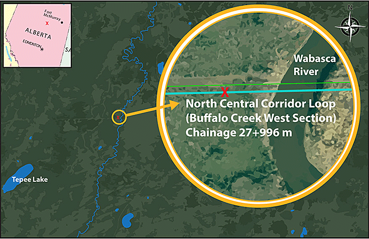
North Central Corridor Loop (Buffalo Creek West Section)
Chainage 27+996 m
Near Fort McMurray, Alberta
The Transportation Safety Board of Canada (TSB) investigated this occurrence for the purpose of advancing transportation safety. It is not the function of the Board to assign fault or determine civil or criminal liability. This report is not created for use in the context of legal, disciplinary or other proceedings. See Ownership and use of content. Masculine pronouns and position titles may be used to signify all genders to comply with the Canadian Transportation Accident Investigation and Safety Board Act (S.C. 1989, c. 3).
Summary
At about 0235 Mountain Standard Time on 17 October 2013, a pipeline rupture occurred on TransCanada PipeLines Limited’s (NOVA Gas Transmission Ltd.) 914-mm-diameter (36-inch-diameter) North Central Corridor Loop Buffalo Creek West Section pipeline, located southwest of Fort McMurray, Alberta. The rupture occurred in a remote location, approximately 150 m west of the Wabasca River (Chainage 27+996 m). At the time of the rupture, the pipeline was transporting sweet natural gas. A crater was created and 5 fragments of pipe were ejected up to approximately 130 m from the rupture site. An estimated 16.5 million cubic metres of natural gas was released. The rupture did not result in a fire. There were no injuries and no evacuation was required.
Factual information
The pipeline rupture occurred on TransCanada PipeLines Limited (NOVA Gas Transmission Ltd.)Footnote 1 (NGTL) 914-mm-diameter (NPSFootnote 2 36) North Central Corridor Loop (NCC Loop) Buffalo Creek West Section between chainage 27+951.6 m and 27+998.4 m (Figure 1). This pipe section is located southwest of Fort McMurray, Alberta, between block valves NCC30-1-BV and NCC20-1-BV, and about 25 km from the Woodenhouse compressor station. The rupture was upstream (i.e., west) of the horizontal directional drill (HDD) portion of the line crossing under the Wabasca River. This location is on Crown land, at the legal land description of SE-01-087-24 W4M. There were no permanent residents in the immediate area, but a seasonal cabin was located approximately 250 m from the rupture location.
The NCC Loop Buffalo Creek West Section shares the right-of-way with the NCC 24 main line (NCC ML). Due to the proximity of the NCC ML at the rupture location, the pressure in the NCC ML was temporarily reduced to 80% of the discovery pressure.
The supply of natural gas was not affected in any residential communities. However, 2 oil sand industry customers had to make temporary arrangements to have gas and/or propane delivered to their site by truck.
Site examination
During site examination, it was determined that:
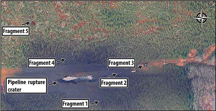
- The pipeline rupture had created a crater approximately 15 m wide, 50 m long and 5 m deep.
- Five pipe fragments were ejected during the rupture and were located within about 130 m of the line break site (Figure 2).
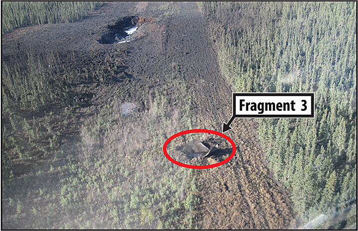
- Fragment 3, located approximately 30 m from the edge of the rupture site, was a 3D-forged 12-degree elbowFootnote 3 with short pupsFootnote 4 attached to each end (Figure 3).
- The soil condition at the rupture site consisted of an organic deposit approximately 0.5 m to 1.5 m thick with underlying clay.
- Approximately 200 m east of the rupture site, the terrain changed to a mineral soil on the banks of the Wabasca River.
- Approximately 350 m west of the rupture site, there was a wetland area.
The 5 pipe fragments and the arrest ends were collected and shipped to the Acuren Laboratory in Edmonton, Alberta, for detailed examination.
Pipeline information
The Buffalo Creek West Section of the NCC Loop is a Class 1Footnote 5 pipe, which extends for 54.3 km, from the Woodenhouse compressor station to valve NCC20-1-BV.
This pipeline was originally approved by the Alberta Utilities Commission (AUC). It was constructed during the winter of 2008 and was placed into service on 20 March 2009, operating under provincial jurisdiction until 15 April 2009, when all NGTL pipelines (including the NCC Loop) were transferred from provincial (AUC) to federal (National Energy Board) jurisdiction.Footnote 6
The maximum operating pressure (MOP), as approved by the National Energy Board (NEB) was 9930 kilopascals (kPa), at a corresponding 79.7% SMYS (specified minimum yield strength). Additional pipe characteristics are summarized in Table 1.
| Wall thickness (mm) | Grade (megapascals [MPa]) |
%SMYS | Coating type | |
|---|---|---|---|---|
| Pipe for the loop | 11.8 | 483 | 80 | Fusion Bond Epoxy System 1A |
| Pipe for the HDD section | 15.7 | 550 | 60 | Fusion Bond Epoxy System 2B |
| Elbows connected to the HDD section | 15.7 | 550 | 60 | Liquid epoxy |
The line pipe consisted of longitudinal seam pipe manufactured using the UOEFootnote 7 process and double-submerged arc welding (DSAW). This pipe was manufactured in 2008 by EVRAZ in Camrose, Alberta. During the manufacturing process, non-destructive testing (NDT) was performed on all welds. The girth welds that were made during fabrication were inspected using radiography. During pipeline construction, the girth welds were inspected using automated ultrasonic testing (AUT) in accordance with Canadian Standards Association (CSA) standard CSA Z662. All of the girth welds were also inspected visually.
The entire pipe was coated with fusion bond epoxy (FBE). The 11.8 mm pipe sections were coated per CSA Z245.20 System 1A. The 15.7 mm pipe sections were coated per CSA Z245.20 System 2B. In addition, the pipe elbows and girth welds were coated with liquid epoxy.
Detection and notification of rupture
On 17 October 2013 at 0235Footnote 8, the rupture was identified by TransCanada PipeLines Limited's (TransCanada) Gas Control while monitoring the Supervisory Control and Data Acquisition (SCADA) pressure trends. Decreases for the Woodenhouse compressor station discharge pressure, the Buffalo North compressor station suction pressure, the Germain meter station delivery pressure and the Livock meter station delivery pressure were observed. At the time of discovery, the operating pressure at the Woodenhouse compressor station was about 9200 kPa.
Subsequently, a number of low pressure shutoff devices tripped and were acknowledged by Gas Control. The pressure was also decreasing on the adjacent NCC ML as the 2 pipelines were operating in common at the time of the rupture.
After the on-call technician was dispatched from the Wildrose Region to investigate, the following notifications were received or initiated:
- At 0308, a low-pressure SCADA alarm occurred at the Livock meter station.
- At 0315, Gas Control notified the Livock sales emergency number of the problem.
- At 0324, Gas Control notified the Germain sales operator of the situation.
- At 0335, Gas Control notified the TransCanada Emergency Management System on-call manager and activated the corporate Emergency Operations Center (EOC).
- At 0348, the Livock field foreman informed Gas Control that they were hearing gas venting in the direction of the NCC pipelines near the Wabasca River.
- At 0355, the Wildrose Region EOC was activated.
Isolation of the failed pipe section
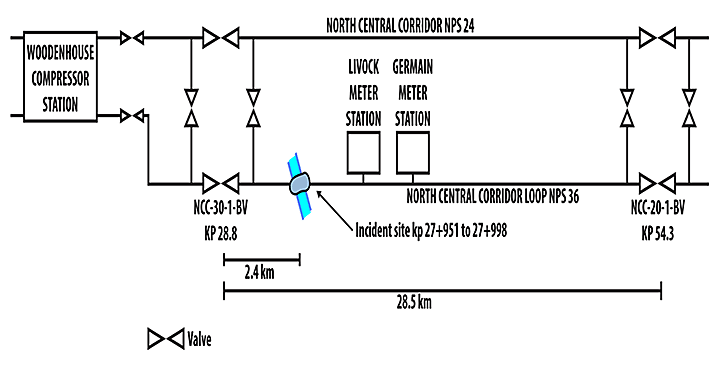
To isolate the failed pipeline section, a number of valves immediately upstream and downstream of the failed location (Figure 4) were closed. Three valves then automatically closed: a block valve (NCC30-1-BV), a cross over valve (NCC30-0-D2) and the Germain sales valve (GMN10-M-1MV1-NCC). At 0754, the mainline to loop crossover valve (NCC20-0-X1) was manually activated to close by local valve control. When valve NCC20-0-X1 was manually activated to close, another block valve (NCC20-1-BV) closed automatically.
At 0815, a helicopter was dispatched to transport TransCanada technicians to the upstream block valve (NCC30-1-BV) and the downstream block valve (NCC20-1-BV) to verify that the valves were closed. By 1500, the block valves on the loop and the upstream crossover valve between the lateral and the loop were confirmed to be closed and sealed. The volume of natural gas released was estimated to be 16.5 million cubic metres.
Pipeline restoration
The failed 12-degree elbow was replaced with a 19.7-mm nominal wall thickness, grade 483, 12-degree elbow. Two screw anchors were installed 25 m upstream of the elbow (spaced approximately 1 meter apart). An additional screw anchor was placed 45 m upstream of the elbow. The 12-degree elbow on the east side of the Wabasca River was proactively replaced with a 19.7 mm nominal wall thickness, grade 483, 12 degree elbow.
Under the direction of NEB Inspection Officer Order KF-001-2013, the pipeline was returned to service on 21 November 2013 with the conditions that there be a maximum pressure of 7168 kPa for the valve section NCC 30-1-BV to NCC 20-1-BV, and that the discharge temperature be restricted to 35 °C at the Woodenhouse compressor station.
Operating history of the pipeline
Just prior to the pipeline rupture, the maximum discharge pressure at the Woodenhouse compressor station had been 9212 kPa at a temperature of 51.5 °C. The set point for the maximum discharge temperature at the Woodenhouse compressor station was 55 °C. In the 48 hours prior to the rupture, the pressure ranged from 7807 kPa to 8960 kPa, as measured at the Livock meter station.
Approximately 50 days prior to the rupture, there was a step increase in the discharge temperature at the Woodenhouse compressor station, due to an increased horsepower requirement to meet downstream customer demand.
As such, in the 50 days prior to the rupture, the pipeline had been experiencing a sustained elevated discharge temperature of at least 42 °C at the Woodenhouse compressor station (Figure 5). At this location, the pipeline had not previously experienced this range of elevated temperatures for an extended period of time.
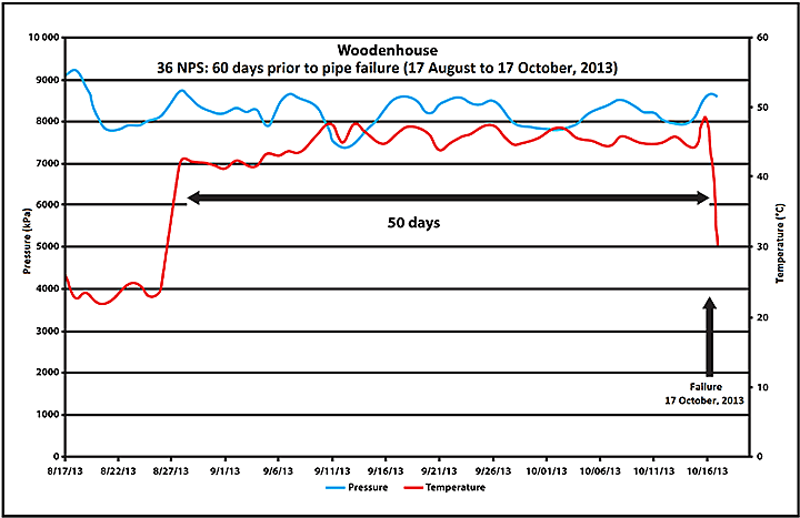
In the 6 months prior to the rupture, the pressure at the Livock sales meter station, 4.4 km downstream of the failure location, had ranged from 6921 kPa to 9273 kPa, with an average of 8501 kPa. Nine hours prior to the rupture, the Paul Lake B compressor station had come offline, resulting in an increase in pressure at the Woodenhouse compressor station. This change was not considered as unusual operations, as it did not result in overpressuring of the NCC Loop.
Design basis memorandum for North Central Corridor Loop Buffalo Creek West Section
The design basis memorandum for the NCC Loop Buffalo Creek West Section specified a maximum discharge temperature of 58 °C at the Woodenhouse compressor station. However, the stress analysis conducted by a contractor for this project had used 45 °C as the maximum discharge temperature. It was indicated that the maximum discharge temperature had not been effectively communicated among TransCanada's project team members and contractors.
Furthermore, the stress analysis used a gas temperature profile for the design, which was later determined to be different from the actual gas temperature profile during operations. The temperature decay model assumed that the gas temperature would reach ground temperature in approximately 10 km following discharge from the compressor station. Based on this assumption, a less conservative linearly decreasing temperature profile was used in the stress analysis.
Design and procurement of pipeline elbows
The NCC Loop Buffalo Creek West Section contained 25 elbows, of which 2 were the over bend elbows used at the Wabasca River HDD crossing. The other 23 elbows were side bends. The elbows were manufactured using a quench and temper process.Footnote 9 Each elbow was fabricated from 2 plates that were formed into 2 halves of elbow. The 2 halves were welded together with longitudinal seam welds located at the intrados (inside curve) and the extrados (outside curve) of the elbow. Short pipe pups were then welded to each end of the elbow using the submerged arc welding (SAW) process.
Twenty-six elbows, including one spare, had been ordered to CSA grade 550 specification. As the matching pipe was grade 483, there was no technical requirement for ordering the elbows at the grade 550 specification. In the technical agreement with the manufacturer, the product ordering requirement was to meet TransCanada's proprietary specifications for fittings TES-FITG-LD, dated 19 January 2007 and CSA Z245.11-05. TransCanada's proprietary specifications for fittings included additional requirements related to mechanical testing, chemistry, dimensions and heat treatment.
The design of the elbows was completed by the manufacturer and was based on the pressure specified by TransCanada. The technical agreement specified that the starting plate thickness for each 3D elbow was to be 1.1 times the adjoining pipe wall thickness. There was no requirement to consider in-service thermal and longitudinal stresses in the design and manufacturing of the elbows, as these elements were addressed in the stress analysis.
The elbow manufacturing process had an established quality assurance (QA) and quality control (QC) process, which included procedures for the verification of purchase orders, validation of specified manufacturing standards, production planning, fabrication, heat treatment, machining, testing, inspection, and certification. As part of TransCanada's QA/QC process for this project, each of the 26 elbow assemblies manufactured for the NCC Loop Buffalo Creek West Section were hydrostatically tested. The hydrostatic tests were conducted at a multiple of 1.4 maximum operating pressure. During hydrostatic testing, two of the elbows failed—one burst and another one bulged.
Subsequent examination of the failed elbows determined that the yield strength had been below the SMYS of 550 MPa. The lowest measured yield strength (representative of the elbow body)Footnote 10 was 459 MPa for the bulged elbow. This elbow had been re-heated to complete proper sizing. During the re-heat procedure, the temperature had exceeded the specified tempering temperature of 593ºC, which may have resulted in a decrease in mechanical properties.Footnote 11
The burst elbow, with a wall thickness of 10.3 mm, exhibited an average yield strength of 533 MPa. This elbow had failed under pre-construction hydrostatic testing due to a combination of wall thickness not meeting the specified requirements and the applied test pressure being higher than the required maximum pressure.
The remaining 24 elbows had passed the hydrostatic test. However, an additional 2 elbows were removed from further consideration after determining that one elbow had low wall thickness and another one had low hardness. For the 22 remaining elbows, a fitness for service assessment was conducted for each elbow, which included a visual inspection, dimensional measurements on the external circumference for all of the elbows, as well as hardness and microstructure testing.
Of the 22 elbows, there were 2 distinct distributions of elbow hardness, a group of high hardness elbows with an average hardness of approximately 230 BHN (Brinell hardness number) and a second group of low hardness elbows with an average hardness of approximately 175 BHN.
Twelve of the 22 elbows had an average hardness of less than 200 BHN. TransCanada determined that additional wall thicknessFootnote 12 would compensate for a decrease in yield strength.
For the 12 lower hardness elbows, ultrasonic measurements were to be taken to confirm the wall thickness. However, for 2 of these elbows, including the elbow that ruptured in service in this occurrence, the measurements had not been taken.Footnote 13 Instead, an incorrect wall thickness value of 19.05 mm was assumed, based on the starting plate thickness stated on the manufacturing design drawings. The actual starting plate thickness was 15.88 mm, just slightly greater than the wall thickness of the matching pipe (15.7 mm). Assuming a grade of 459 MPa and a wall thickness of 19.05 mm, the elbow that ruptured in service was calculated to have a pressure rating of 11 480 kPa, exceeding the maximum operating pressure for the pipeline of 9930 kPa.
All of the remaining 22 elbows and 4 replacement elbows were then hydrostatically tested for a second time to a higher pressure (12 600 kPa). They were accepted for use in the construction of the pipeline as the hydrostatic test resulted in no failure, leakage or impairment of serviceability. Following the fitness for service assessment, the decision was made to accept the 22 elbows, including the group of 12 elbows with lower hardness. These elbows, which resisted the higher applied pressures of the hydrostatic test, were deemed to be fully suitable for the project.
TransCanada's quality assurance process for purchasing and accepting elbows
At TransCanada, manufacturers of high-grade large-diameter (NPS 16 and greater) carbon steel elbows must be pre-qualified. In 2008, when the elbow order was placed, the elbow manufacturer was an approved manufacturer for this type of fitting.
TransCanada had implemented a quality assurance process for purchasing and accepting elbows. The quality assurance process for procuring the elbows for the NCC Loop project included:
- TransCanada's Material Engineering group developed, with the manufacturer, a technical agreement that summarized the manufacturer's starting material specifications, welding procedures and the minimum design criteria for the starting plate thicknesses.
- The purchase order, when placed, contained the technical information required to design the elbows in accordance with CSA Z245.11-05 and TransCanada's proprietary specifications for fittings (TES-FITG-LD).
- Upon completing the elbow design, the manufacturer provided drawings to the Material Engineering group for review and approval.
- TransCanada used third-party inspectionFootnote 14 during manufacturing.
- TransCanada required the manufacturer to provide materials test reports for review and documentation.
Standards for pipeline fittings
This pipeline was designed and constructed in accordance with CSA Z662-07, which references CSA Z245.11-05 for pipeline fittings.
The relevant clauses of CSA Z245.11-05 include:
- CSA Z245.11-05, clause 4.3.1, which states:
The pressure rating for fittings shall be calculated in accordance with the rules established in the applicable ASME Standard (B31.1, B31.3, B31.4, B31.5, B31.8, or B31.9) and in the applicable clauses of CAN/CSA Z-662.
The applicable American Society of Mechanical Engineers (ASME) standard for this application was ASME B31.8, which requires that elbows “shall have pressure and temperature ratings based on stresses for pipe of the same or equivalent material.”
- CSA Z245.11-05, clause 4.3.2, which states:
After installation, fittings shall be capable of withstanding the pressure test at a pressure level required to develop a hoop stress equal to the specified minimum yield strength for pipe of equivalent grade and wall thickness attached to the fitting, or at a higher pressure level specified in the purchase order, without failure, leakage, or impairment of serviceability or mechanical properties.
In addition, the relevant clauses of CSA Z662-07 include:
- CSA Z662-07, clause 4.3.12.1, which states that components “shall be designed to withstand operating pressures and other specified loadings.”
- CSA Z662-07, clause 4.2.1.2, which states:
The effect of external pressures and loadings on the pipe during installation and operation shall be accounted for using good engineering practice. The pipe wall thickness selected shall provide adequate strength to prevent excessive deformation and collapse, taking into consideration mechanical properties, wall thickness tolerances, ovality, bending stresses, and external reactions (see clauses 4.6 to 4.10).
- CSA Z662-07, clause 4.2.2.2, which states that the “effects of thermal expansion and contraction shall be provided for in the design as specified in clauses 4.6 to 4.10.”
Laboratory analysis of failed pipe
The 5 pipe fragments and the arrest ends from the rupture site were analyzed at Acuren's laboratory in Edmonton, Alberta. The total retrieved length of pipe was 46.7 m. The pipe fragments included 4 primarily round pieces and a longitudinally split section that contained the 12-degree elbow.
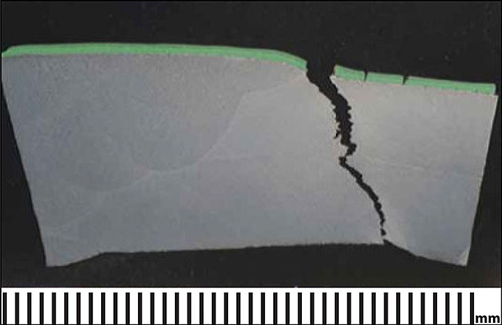
Laboratory analysis determined that the failure initiated within the 12-degree elbow. Prior to rupture, the elbow had been altered to about 15.4 degrees and had expanded about 5.9%. The failure initiation point was located mid-span of the elbow and coincident with the toe of the intrados weld cap. From the initiation point, the fracture had propagated through the wall thickness at approximately 45 degrees (Photo 1). The fracture was entirely ductile in nature, resulting from stresses that exceeded the strength of the elbow.
Mechanical testingFootnote 15 (i.e., yield strength, ultimate tensile strength and percent elongation) determined that the elbow had not been compliant with CSA Z245.11 grade 550. The mechanical testing results were however compliant with CSA Z245.11 grade 483, which was the specified grade for the matching pipe. Charpy impact testingFootnote 16 determined that the elbow and the pups from each side of the elbow had met the requirements of CSA Z245.11. There was no indication of corrosion, stress corrosion cracking, mechanical damage, or material and manufacturing defects.
Finite-element analysis of elbow
A finite-element analysis (FEA) was conducted to evaluate the range of stresses at the elbow that would be necessary to cause failure. Based on the temperature and pressure at the time of failure, the elbow would have experienced large through-wall plastic stresses at the intrados due to a bend-closing mechanism. The stress and strain resulting from the temperature and pressure conditions was sufficient to induce the initiation of the line break.
Regulatory requirements for pipeline integrity management
In 2009, at the time the NCC Loop was constructed, section 40 of the NEB's Onshore Pipeline Regulations (OPR) specified that “[a] company shall develop a pipeline integrity management program”.
At that time, there was no regulatory requirement for an integrity management program to track conditions that might impact operations that could arise during construction.
In 2013, section 40 of the OPR was amended to specify:
A company shall develop, implement and maintain an integrity management program that anticipates, prevents, manages and mitigates conditions that could adversely affect safety or the environment during the design, construction, operation, maintenance or abandonment of a pipeline.
NEB-regulated companies must demonstrate a proactive commitment to improvement in safety. These pipeline companies are required to incorporate an integrity management program (IMP) into their day-to-day operations. Based on tools, technology and actions, the IMP will enable the pipeline company to predict and prevent failures.
TransCanada's pipeline integrity management program
TransCanada's IMP for gas pipelines is called Canadian Gas Pipeline Integrity Management Program (Gas Pipeline IMP). Within the Gas Pipeline IMP, 9 hazard categories were evaluated. They were divided in 3 groups as follows:
- Time dependent hazards (i.e., external corrosion, internal corrosion, and stress corrosion cracking)
- Stable or resident hazards (i.e., manufacturing, welding or fabrication defects, and equipment failure)
- Time independent hazards (i.e., weather and outside forces, mechanical damage, and incorrect operations)
With respect to manufacturing defects, TransCanada's IMP indicated that manufacturing specifications, incorporating measures to ensure material quality and consistency and adherence to standards, must be implemented.
National Energy Board's audit of TransCanada's integrity management program
The NEB requires regulated pipeline companies to anticipate, prevent, mitigate and manage any hazards and risks associated with their operations. The NEB uses a risk-informed approach to identify pipeline companies requiring regulatory oversight. Taking a proactive approach, the NEB conducts compliance verifications, including inspections and audits, to identify potential issues within a pipeline company's integrity management program. Over the course of these audits, a pipeline company must demonstrate the adequacy and effectiveness of its IMP, as well as its compliance with NEB requirements through interviews with company personnel and the provision of supporting documentation. Following the audits, the companies must submit and implement a corrective action plan to address any identified non-compliances. The results of the audits are used as part of the NEB's risk-informed life cycle approach to compliance assurance.
NEB's most recent audit of TransCanada's integrity management program had been initiated in November 2012 and included 9 management system sub-elements:
- Hazard identification, risk assessment and control
- Organizational structure, roles and responsibilities
- Training, competence and evaluation
- Operations control – normal operations
- Operations control – upset or abnormal operating conditions
- Inspection, measurement and monitoring
- Corrective and preventive actions
- Internal audit
- Management review
These sub-elements were selected based on a risk-informed approach, focusing on areas within the pipeline industry with the highest rates of non-compliance. In addition, the TransCanada audit activities had been modified to evaluate the allegationsFootnote 17 of potential non-compliance that had been brought to the attention of NEB by a complainant. The modified audit protocol included four additional assessments:
- TransCanada's practices relating to welding inspections and non-destructive examination when conducted by certified, third party experts reporting directly to TransCanada, independent of the contractors performing the work
- TransCanada's internal practice of engineering guidance
- Training program for internal inspectors on new non-destructive examination procedures
- Role and responsibilities of the QA/QC manager
The NEB issued its final audit report in February 2014. It indicated that the processes that TransCanada had in place were able to identify the majority, and most significant, of its hazards and risks. TransCanada was also fully compliant in 5 sub-elements of the audit, including organizational structure, role and responsibilities; training, competence and evaluation; operational control – normal operations; corrective and preventive actions; and internal audit.
However, TransCanada was non-compliantFootnote 18 with parts of 4 sub-elements of the audit, including hazard identification, risk assessment and control; operational control – upset or abnormal operating conditions; inspection, measurement and monitoring; and management review (Appendix).
In addition, TransCanada's internal audit and investigation relating to its compliance with technical standards and procedures had confirmed several of the allegations of regulatory non-compliance identified by the complainant. TransCanada then developed and implemented actions to correct and prevent similar occurrences for the confirmed non-compliances. These corrective actions were taken prior to the NEB's investigation into the allegations from the complainant.
TransCanada's internal audit of its integrity management program
TransCanada conducted an internal audit of potential non-compliance to its IMP in May 2012. A number of evaluations, determinations and changes were made by TransCanada.
In conjunction with the internal audit, TransCanada implemented a review of the engineering requirements in its practice of engineering specification. This specification included guidance on the requirements for both internal engineering and third party engineering. The specification outlined authentication requirements for engineering documents produced by or for TransCanada. In 2012, mandatory training on TransCanada's practice of engineering was implemented. The Capital Project Management System has since been implemented to mandate the requirements for internal engineering reviews of the design of new pipelines. The Capital Project Management System also outlines stage gate requirements for reviews at different stages of the design phase, for example at 30%, 60% and 90% of design completion.
The internal audit determined that a formal audit and investigation process existed within TransCanada, but there were opportunities for continuous improvement.
Analysis
The occurrence
The pipeline ruptured upstream (west) of the horizontal directional drill portion of the line crossing under the Wabasca River. The pipeline failure had initiated at a fabricated over-bend elbow. From the initiation point (mid-span of the elbow and coincident with the toe of the intrados weld cap), the fracture propagated through the wall thickness at approximately 45 degrees, resulting in the in-service rupture. Due to the internal pipe pressure, 5 pipe fragments, including the elbow, were ejected during the rupture and were located within about 130 m of the line break site. The natural gas released from the in-service rupture did not ignite.
During normal pipeline operations, thermal expansion had developed in the pipeline that exerted force on the elbow, resulting in increased stress at the intrados of the elbow. Over a 50-day period prior to the rupture, the pipeline had been operating at a sustained temperature ranging from 42 °C to 48 °C and at a maximum pressure in the range of 9200 kPa.
The manufacturer had designed and fabricated the pipeline elbow in accordance with Canadian Standards Association (CSA) standard CSA Z245.11-05, based on the matching pipe parameters and other technical requirements specified by TransCanada PipeLines Limited (TransCanada). However, when the pipeline was designed, the stress analysis had used a lower maximum operating temperature at the Woodenhouse compressor station (i.e., 45 °C instead of 58 °C) and a non-conservative temperature decay model. The maximum possible discharge temperature had not been effectively communicated among the project team members and contractors at the design stage, resulting in the use of a lower temperature during the design process. As a result, the pipeline design did not fully address its potential operating envelope (i.e., pressure and temperature) and the design did not properly account for the threat of thermal expansion.
The manufacturer had been pre-qualified by TransCanada. In addition, TransCanada had implemented a quality assurance (QA) process for the purchasing and acceptance of pipeline elbows. However, the use of the incorrect design parameter and the non-conservative temperature decay model were not identified by TransCanada's quality assurance process. If the stress analysis conducted during pipeline design does not fully address the potential operating envelope (i.e., pressure and temperature), the pipeline or its components may not be sufficiently robust, increasing the risk of in-service ruptures.
Quality assurance process for pipeline fittings
As part of TransCanada's quality assurance and quality control (QC) process for the project, all elbows were hydrostatically tested prior to being sent to the field. During the pre-construction in-shop hydrostatic tests for the Buffalo Creek West Section, 2 elbows experienced failures as one elbow burst and a second elbow bulged. The bulged elbow had decreased mechanical properties while the burst elbow had a wall thickness that did not meet the specified requirements, in addition to having decreased mechanical properties.
The elbow manufacturer's quality assurance process did not include specific requirements to verify the hydrostatic test pressure, the material properties and the wall thickness of each manufactured fitting. If the quality assurance and quality control process does not ensure that all pipeline fitting standards and design specifications are addressed, the pipeline fitting may not be suitable for the full operating envelope (i.e., pressure and temperature) of the pipeline, increasing the risk of in-service failures.
Fitness for service assessment of pipeline elbows
Following the examination of the two failed elbows, a fitness for service assessment was conducted for the remaining elbows. The assessment included a visual inspection, dimensional measurements, as well as hardness, microstructure, and hydrostatic testing. Twenty-two of the original 26 elbows were accepted for the project. With respect to the elbow that ruptured in this occurrence, its wall thickness was not directly measured but was instead based on information from the manufacturing design drawings, which thereby overstated its value by 3.17 mm. As a result, the elbow's calculated internal pressure rating was also overstated.
The pipeline elbows installed on the Buffalo Creek West Section were deemed to be fully suitable after undergoing the fitness for service assessment, including a post-construction hydrostatic test to 12 600 kPa without failure, leakage or impairment of serviceability. The test pressure was greater than the maximum allowable operating pressure for the pipeline, which is 9930 kPa.
Pipeline integrity management program
In the category of “stable or resident hazards”, TransCanada's integrity management program (IMP) considers the following threats: manufacturing defects, welding or fabrication defects, and equipment failure. For each type of threat, TransCanada's IMP included a number of mitigation strategies. For example, threats due to manufacturing defects were mitigated by incorporating measures to ensure material quality and consistency and adherence to standards.
However, in this occurrence, the elbows installed in the pipeline had not been manufactured to the required specifications, but were accepted for installation on the basis of a fitness for service assessment. However, an incorrect parameter and temperature decay model was used in the design of the pipeline, which constitutes a type of threat that was not specifically considered in TransCanada's IMP.Footnote 19 If a pipeline company's integrity management program does not identify and mitigate the threat of improper design, there is an increased risk of pipeline rupture when operating near the upper limits of the pipeline.
Audit of TransCanada's pipeline integrity management program
The NEB initiated an audit of TransCanada's IMP in November 2012, focusing on the company's management systems. As part of the audit, the NEB also examined elements of TransCanada's pipeline integrity management practices, including engineering guidance and quality assurance/quality control. Although the NEB identified some non-compliances to TransCanada's management systems, the audit determined that the processes that TransCanada had in place were able to identify the majority, and most significant, of its hazards and risks.
Findings
Findings as to causes and contributing factors
- The pipeline failure initiated at a fabricated over bend elbow at the west end of the horizontal directional drill section under the Wabasca River.
- From the initiation point (mid-span of the elbow and coincident with the toe of the intrados weld cap), the fracture propagated through the wall thickness at approximately 45 degrees, resulting in the pipeline rupture.
- Thermal expansion had developed in the pipeline that exerted force on the elbow, resulting in increased compressive stress at the intrados of the elbow. This increased stress had occurred over a 50-day period when the pipeline was being operated at a sustained temperature ranging from 42 °C to 48 °C and at a maximum pressure in the range of 9200 kPa.
- The elbow's internal pressure rating was overstated as the calculation had used a wall thickness based on information from the manufacturing design drawings, instead of from a direct measurement.
- During the pipeline design, the stress analysis had used a lower maximum operating temperature at the Woodenhouse compressor station and a non-conservative temperature decay model, resulting in a pipeline design that did not fully address the potential operating envelope (i.e., pressure and temperature) of the pipeline.
- The use of the incorrect design parameter and the non-conservative temperature decay model were not identified by TransCanada PipeLines Limited's quality assurance process.
Findings as to risk
- If the stress analysis conducted during pipeline design does not fully address the potential operating envelope (i.e., pressure and temperature), the pipeline or its components may not be sufficiently robust, increasing the risk of in-service ruptures.
- If the quality assurance and quality control process does not ensure that all pipeline fitting standards and design specifications are addressed, the pipeline fitting may not be suitable for the full operating envelope (i.e., pressure and temperature) of the pipeline, increasing the risk of in-service failures.
- If a pipeline company’s integrity management program does not identify and mitigate the threat of improper design, there is an increased risk of pipeline rupture when operating near the upper limits of the pipeline.
Other findings
- The maximum possible discharge temperature at the Woodenhouse compressor station had not been effectively communicated among the project team members and contractors at the design stage, resulting in the use of a lower temperature during the design process.
- The elbow manufacturer's quality assurance process did not include specific requirements to verify the hydrostatic test pressure, the material properties and the wall thickness of each manufactured fitting.
- The pipeline elbows installed on the Buffalo Creek West Section were deemed to be fully suitable after undergoing a fitness for service assessment, including a post-construction hydrostatic test to 12 600 kPa without failure, leakage or impairment of serviceability.
- Although the National Energy Board identified some non-compliances to TransCanada PipeLines Limited's management systems, the audit determined that the processes TransCanada PipeLines Limited had in place were able to identify the majority, and most significant, of its hazards and risks.
Safety action
Safety action taken
The following safety actions were taken by the National Energy Board (NEB):
- Following the occurrence, the NEB initiated an investigation for the purpose of verifying compliance with its regulations.
- In November 2013, the NEB issued Inspection Officer Order KF-001-2013, limiting the pressure for the valve section between NCC30-1-BV and NCC20-1-BV to 7168 kPa and restricting the discharge temperature to 35 °C at the Woodenhouse compressor station.
- In October 2014, following the evaluation of an engineering assessment submitted by TransCanada PipeLines Limited (TransCanada), the NEB issued Inspection Officer Order KF-001-2014, allowing the pipeline to operate at a maximum pressure of 7750 kPa while maintaining the discharge temperature at the Woodenhouse compressor station to 35 °C.
- The NEB is also considering issuing safety advisories regarding the consideration of design parameters and assumptions, thermally induced stresses and lower strength fittings.
The following safety actions were taken by TransCanada:
- Sixteen elbows on the NCC Loop Buffalo Creek West Section were excavated in order to install composite Armor Plate® Pipe Wrap. These elbows included the 10 elbows that had been identified as having an average hardness less than 200 BHN (Brinell hardness number). The addition of the Armor Plate® Pipe Wrap to the elbow was estimated to add about 95 MPa to its effective yield strength.
- Thirteen of the 16 excavated elbows were measured for geometry (i.e., diameter and deviation from circularity, and angle) using a long range laser. It was confirmed that there were no gross deformations in the elbow at these locations.
- TransCanada has begun developing a parametric model to examine the threat of thermal expansion. This model will be used to assess TransCanada's pipelines (including elbows) for potential exposure to thermal expansion loading. Identified locations that may be susceptible to the effects of stresses associated with thermal expansion will be prioritized for additional detailed stress analysis. If excessive stresses are confirmed, mitigation actions could include restrictions to discharge temperature, localized pipeline reinforcement, enhanced restraint of the bend, or replacement of the pipe and bend.
- Within the project design process, the requirement to demonstrate compliance to the stress requirements of pipeline as per Canadian Standards Association (CSA) standard CSA Z662-11 was reinforced.
- TransCanada increased its design factor (from 1.10 to 1.25) for large-diameter 3D elbows (NPS [nominal pipe size] 16 and greater), which will increase the minimum starting plate thickness and strengthen the elbows' ability to withstand combined stresses.
- TransCanada enhanced its third-party inspection requirements and third-party auditing protocol to validate compliance of fittings to applicable standards and specifications.
- TransCanada reviewed its commissioning process and the project turnover memorandum process to incorporate additional validation requirements for design parameters and design assumptions.
- TransCanada has begun developing a stress analysis specification to ensure that new pipeline projects establish a temperature design basis that is representative of the entire operating envelope of the pipeline.
- TransCanada initiated a 3-year research program with CANMET to develop improved quality assurance and quality control measures and an inspection test protocol for validating the yield strength of pipeline fittings.
The following safety actions were taken by the elbow manufacturer:
- Following extensive testing of the controls of the heat treatment furnaces, the heat treatment and furnace temperature monitoring processes were modified to improve fitting quality. The effectiveness of these changes was confirmed by testing.
- The quality assurance and quality control process was amended to require that the thickness of every plate being received into the plant is measured and that any plate whose thickness is less than the nominal specified thickness is rejected. This will ensure that all fittings are made from plate with sufficient starting wall thickness.
This report concludes the Transportation Safety Board's investigation into this occurrence. The Board authorized the release of this report on 23 September 2015. It was officially released on 3 November 2015.
Appendix - National Energy Board's audit expectations of a pipeline company management system and protection program
The National Energy Board's audit expectations of a pipeline company management system and protection program are set out in the National Energy Board Management System and Protection Program Audit Protocol, and include the following:
- Hazard identification, risk assessment and control: The expectation is that the company shall be able to demonstrate a procedure to identify all possible hazards. The company shall assess the degree of risk associated with these hazards. The company shall implement control measures to minimize or eliminate the risk.
- Operational control – Upset or abnormal operating conditions: The expectation is that the company shall maintain plans and procedures to identify the potential for upset or abnormal operating conditions, accidental releases, incidents and emergency situations. The company shall define proposed responses to these events and prevent and mitigate the likely consequence of these events. The procedures must be periodically tested, reviewed and revised where appropriate.
- Inspection, measurement and monitoring: The expectation is that the company shall develop and implement surveillance and monitoring programs. These programs should address contract work being performed on behalf of the company. The company should integrate the surveillance and monitoring results with other data in risk assessments and performance measures, including proactive trend analyses. The company shall have documentation and records of its surveillance and monitoring programs.
- Management review: The expectation is that the company shall formally review the management and protection programs for continuing suitability, adequacy and effectiveness. The review should be formal and documented and should occur on a regular basis. The management review should include a review of any decisions, actions and commitments that relate to the improvement of the programs and the company's overall performance.
Source: National Energy Board, National Energy Board Management System and Protection Program Audit Protocol, 17 July 2013