Engine failure and collision with terrain
Oceanview Helicopters Ltd.
Hughes 369D (helicopter), C-FOHE
Paynton, Saskatchewan, 7 nm N
The Transportation Safety Board of Canada (TSB) investigated this occurrence for the purpose of advancing transportation safety. It is not the function of the Board to assign fault or determine civil or criminal liability. This report is not created for use in the context of legal, disciplinary or other proceedings. See Ownership and use of content. Masculine pronouns and position titles may be used to signify all genders to comply with the Canadian Transportation Accident Investigation and Safety Board Act (S.C. 1989, c. 3).
Summary
On 22 October 2015, an Oceanview Helicopters Ltd. Hughes 369D (registration C-FOHE, serial number 410942D) was conducting aerial work on power lines in the vicinity of Paynton, Saskatchewan, with the pilot and an external platform worker on board. At 1342 Central Standard Time, while installing a marker ball in a hover at approximately 325 feet above ground level, the helicopter experienced an engine failure, descended suddenly, and collided with the terrain. The pilot and external platform worker were fatally injured, and the helicopter was destroyed in a post-impact fire. The emergency locator transmitter activated on impact, but was destroyed by the post-impact fire.
Factual information
History of the flight
On 22 October 2015, at approximately 0830,Footnote 1 the pilot departed the North Battleford Airport (CYQW), Saskatchewan, and flew the Hughes 369D helicopter (registration C-FOHE, serial number 410942D) to a job site near Paynton, Saskatchewan. After landing, the pilot conducted the morning safety briefing with the external platform worker and ground crew and discussed the operational plan for the day. The plan was for the pilot and external platform worker to install marker balls onto power lines that spanned the North Saskatchewan River in the vicinity of Paynton. After the briefing, the remainder of the morning was spent installing several marker balls.
The helicopter crew stopped to eat lunch and to refuel the helicopter at approximately 1200, and resumed marker ball installation at about 1330. While the first marker ball was being installed after lunch, a ground crew member took a video of the installation. The video captured the helicopter's subsequent sudden descent.
The video revealed that, while the helicopter was in a hover facing northeast, a yellow flame came from the engine exhaust, followed by a puff of black smoke. The helicopter was seen backing away from the power line and descending in a left-hand rotation. The helicopter subsequently collided with the terrain on an island in the river, which was not captured on the video. The pilot and external platform worker were fatally injured, and the helicopter was destroyed in a post-impact fire.
Company information
Oceanview Helicopters Ltd. ( Oceanview) is a commercial air service that, at the time of the occurrence, operated 5 helicopters under Subparts 702 and 703 of the Canadian Aviation Regulations (CARs) providing aerial work and air charter services.Footnote 2 Although it was not a regulatory requirement, Oceanview had implemented a safety management system in 2009.
Electrical utility company and contractor oversight
SaskPower is an electrical utility company that provides electricity to the province of Saskatchewan. SaskPower had contracted Forbes Bros. Ltd., a power line construction company, to construct and erect hydro towers and to string power lines. Oceanview was contracted by Forbes Bros. Ltd. to carry out aerial work and install marker balls on power lines strung over the North Saskatchewan River.
Many electrical utility companies and contractors that conduct this type of work develop standard operating procedures (SOP) or aircraft operation programs (AOP). These procedures provide a measure of safety and regulatory guidance for company employees who may engage in aerial operations.
Although SaskPower did have AOPs for airplane operations, it did not have any SOPs or AOPs published for helicopter operations. Because SaskPower had no control over the aerial work being conducted, Forbes Bros. Ltd. and Oceanview were expected to provide the necessary oversight.
Forbes Bros. Ltd. has SOPs in place for helicopter aerial work and external work platformFootnote 3 operations. The SOPs require the helicopter to be operated in accordance with Transport Canada (TC) regulatory requirements, the aircraft flight manual, and flight manual supplements. Procedures defined in an SOP or an AOP may vary from company to company, but may not be less restrictive than the regulatory requirements set by TC.
External loads
Helicopters are used for a variety of aerial work, including external load operations. Such operations are categorized into 4 groups, depending on the work performed and the design limitations of the helicopter. TC defines external loads as follows:
helicopter Class A external load means an external load that cannot move freely, cannot be jettisoned and does not extend below the landing gear;
helicopter Class B external load means an external load that can be jettisoned and that is not in contact with land, water or any other surface;
helicopter Class C external load means an external load that can be jettisoned and that remains in contact with land, water or any other surface;
helicopter Class D external load means an external load with a person carried externally or any external load, other than a Class A, B or C external load.Footnote 4
The aerial work conducted during the occurrence flight included an external platform worker; therefore, the operation was considered a Class D external load operation. CARs and the applicable commercial air service standards specify that single-engine helicopters may be used in Class D external load operations provided that the load does not extend below the landing gear and that the personnel-carrying device has airworthiness approval. Conversely, if the Class D external load extends below the landing gear, a multi-engine helicopter that is capable of hovering with one engine inoperative at the existing weight and altitude is to be used.Footnote 5 Oceanview was appropriately equipped and approved by TC to conduct Class D external load operations.
Aircraft information
The Hughes 369D, also referred to as an MD Helicopters Inc. 369D, was a 5-place, single-turbine-engine (Rolls Royce 250-C20B, serial number CAE832457) helicopter equipped with a 5-bladed, fully articulated main rotor system and a 2-bladed, semi-rigid type, anti-torque tail rotor. The helicopter was certified with a maximum take-off weight of 3000 pounds and for day and night flights under visual flight rules.
The helicopter had skid-type landing gear and was modified with an external work platform under the authority of Supplemental Type Certificate (STC) C-LSH11-012/D. The STC allowed the helicopter to carry out Class D external load operations. The helicopter was also modified with an inlet barrier filter (IBF) system under the authority of STC SH04-24. The IBF system provides enhanced filtration of the inlet air to the compressor to protect it from debris and foreign object damage.
The helicopter had accumulated 14 335 flight hours, and there were no deferred or outstanding defects. Before takeoff for the occurrence flight, there were no known technical difficulties with the helicopter.
The helicopter was not equipped with any recording devices, such as a cockpit voice recorder or a flight data recorder, nor were such devices required by regulation.
Wreckage and impact information
The accident site was located on an island in the North Saskatchewan River. The terrain was a flat wooded area, consisting of small trees, hedges, and shrubs. The helicopter struck the ground in a level attitude with a high rate of vertical descent and no forward speed. The helicopter did not leave a wreckage trail and came to rest facing northeast. A post-impact fire consumed approximately 80% of the helicopter structure and the surrounding vegetation.
Damage to the main and tail rotor blades indicated very low rotor torque and speed at the time of impact. An inspection of the rotor system revealed that there was continuity from the main rotor transmission to the main rotor hub. Inspections of the engine and flight controls for continuity were inconclusive because of the extent of the fire damage. Inspections of several components, including the oil and fuel filters, were also inconclusive because of fire damage.
An inspection of the engine revealed that the accessory gearbox had been completely consumed by the post-impact fire. The rest of the engine was secured and taken to the TSB's regional wreckage examination facility for further analysis.
Weight and balance
The helicopter had an estimated 300 pounds of fuel on board and a gross weight of approximately 2710 pounds at the time of the occurrence. A review of the empty and operational weight and balance for the occurrence flight revealed that the helicopter was within the specified limitations.
Personnel information and training
Pilot
The pilot held a commercial helicopter licence, restricted to daylight flying only, and had started at Oceanview in September 2008. Records indicate that the pilot was certified and qualified for the flight in accordance with existing regulations. The pilot had completed recurrent flight training on 22 February 2015 and external work platform recurrent training on 03 March 2015.
| Total flying hours | 21 992 |
|---|---|
| Hours on type | 7 621 |
| External work platform | 336 |
| Hours in the last 7 days | 4.2 |
| Hours in the last 30 days | 4.2 |
| Hours in the last 90 days | 39.2 |
The pilot had been on duty for 6.5 hours at the time of the occurrence and had received a minimum of 14 hours off duty before the work period. The day of the occurrence was the pilot's 8th workday after having 44 days off. The pilot had not flown since 17 October 2015, and the pilot's schedule during the 4 days before the occurrence consisted of non-flying duties assigned by the company. The investigation concluded that fatigue did not play a role in the accident.
Platform worker
The platform worker had been an employee of Forbes Bros. Ltd. since 2006. He was employed as a ground crew lineman and, in 2013, received the required training and certification to conduct work as a Class D external platform worker on helicopters.
Meteorological conditions
Approximately 18 minutes after the accident, at 1400, the aerodrome routine meteorological report for CYQW, located approximately 38 nautical miles southeast of the occurrence, indicated winds 310° true at 13 knots, gusting to 19 knots, visibility 9 statute miles, clear skies, temperature 14 °C, dew point 14 °C, and altimeter setting 29.90 inches of mercury. The weather near the site was slightly overcast with a very light breeze.
Marker ball installation
Marker balls are used to identify overhead power lines, overhead shield wires, and guy wires. They are made of a lightweight thermal plastic, are spherical in shape, and are of a clamshell configuration to allow them to be installed on the power line. Marker balls are used in airport and heliport approach areas and on power lines spanning long distances across canyons, lakes, and rivers.
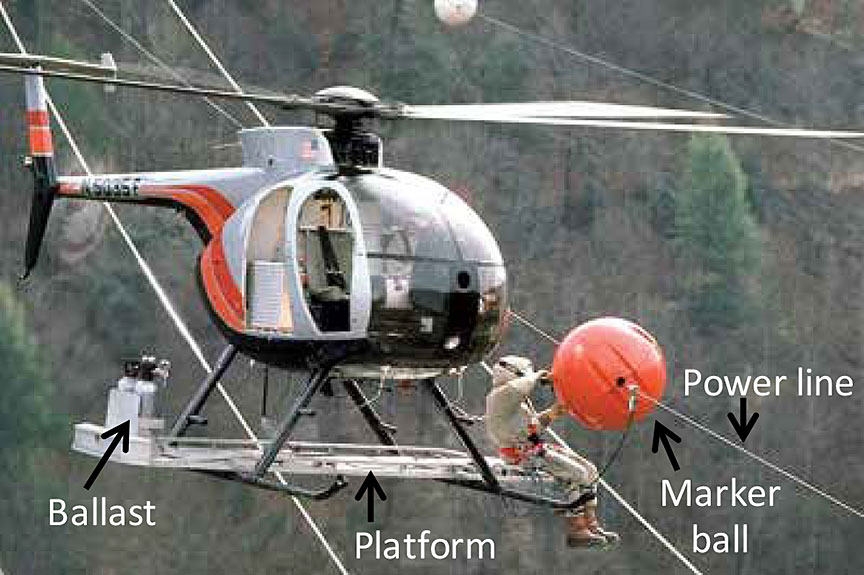
Helicopters are used to install marker balls when ground equipment cannot be used because of the terrain or the height of the power lines. The helicopter is equipped with an external work platform mounted to the top of the landing gear skid. The external platform worker sits on the platform and is secured using a lap belt and torso tether. The marker ball is placed on the worker's lap for takeoff. The helicopter then approaches the power line to allow the worker to install the marker ball (Photo 1). Ballast weights are secured onto the opposite side of the external work platform to counter the weight of the platform worker and to provide lateral stability for the helicopter.
Autorotation
When a helicopter loses engine power, a safe landing can be achieved by conducting an autorotation landing. Autorotation is a condition in flight in which the helicopter descends without engine power applied to the main rotor. Main rotor revolutions per minute (rpm) and the resultant lift are derived from the movement of air up through the main rotor blades/disc during the helicopter's descent, which creates an autorotative force. For the autorotation landing to succeed, the helicopter requires sufficient main rotor rpm and forward airspeed. As the helicopter approaches the touchdown point, the pilot flares the helicopter to slow the forward speed. This flare also increases the main rotor rpm as the helicopter decelerates. The pilot can then use the increased main rotor rpm to arrest the descent and settle on the ground.
An autorotation landing is a challenging manoeuvre for any helicopter pilot, as it requires skills that are not used in normal operations.
Single-engine helicopter hover operation
All helicopter operations include a state of hoverFootnote 6 during various transitions in flight, such as from vertical ascent to forward flight. However, time spent in a hover is relatively short. The nature of marker ball installation and various other aerial operations requires the helicopter to be in a hover for prolonged periods. If an engine failure occurs while the helicopter is in a hover, a minimum altitude is required for the helicopter to initiate a descent and gain sufficient airspeed to conduct a successful autorotation landing.
The airworthiness standards listed in the CARs require helicopters to carry a rotorcraft flight manual (RFM) on board during flight operations. Footnote 7 The RFM contains information (such as limitations, emergency procedures, normal procedures, performance data, weight, and balance) that applies to that specific helicopter. Regulatory compliance with the RFM is confined to the Limitations section of the manual. Performance data in the Hughes 369D RFM include a height velocity diagram, in which the cross-hatched region of the diagram represents combinations of airspeed and altitude from which a successful autorotation landing is unlikely (Figure 1).
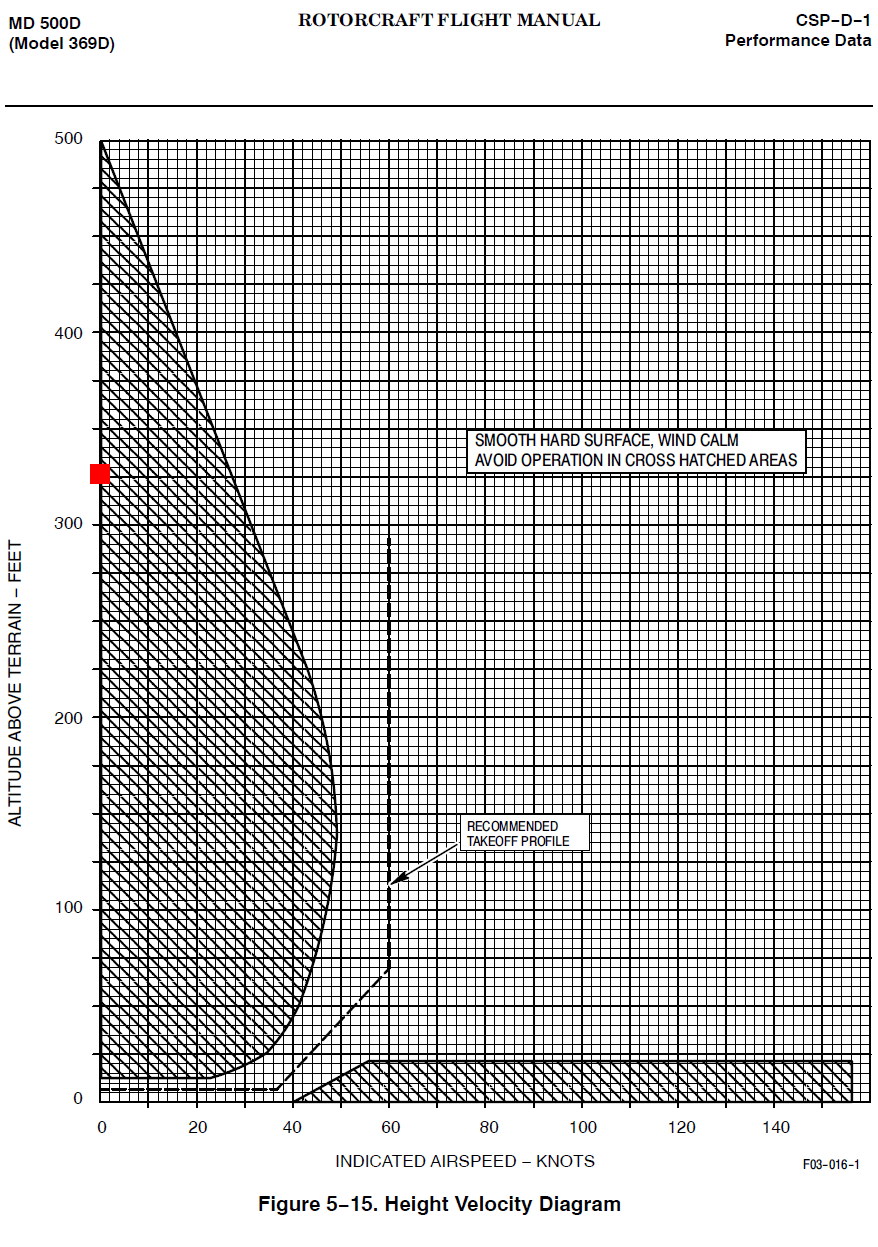
The Hughes 369D RFM also states: "Operation of the helicopter in the cross-hatched area is not prohibited, but should be avoided."Footnote 8 In addition, the RFM emergency procedures state, "Flight within the cross-hatched regions represent [sic] airspeed/altitude combinations from which a successful autorotation landing may be difficult to perform. Operation within the cross-hatched area should be undertaken with caution."Footnote 9 At the time of the engine failure, the helicopter was at 325 feet above ground level in a hover with an airspeed of 0 knots, which placed the helicopter within the cross-hatched region of the diagram in Figure 1 (marked with red square).
Some companies have introduced their own requirements to include restrictions for single-engine helicopter operation in a prolonged hover. A twin-engine helicopter has the redundancy of a second engine, should one engine fail. In that event, multi-engine helicopters may use the power from the remaining engine to control the rate of descent or to hover, if the weight and altitude allow.
Survivability
The accident occurred on an uninhabited island, and first responders had to swim across the river and hike through dense bush to gain access to the site.
At the time of the engine failure, the helicopter was in a hover at an altitude from which a successful autorotation landing was unlikely. Although the autorotative force required for a successful autorotation landing was not generated, the helicopter had attained a significant vertical rate of descent just before impact; the investigation determined that it was approximately 2600 feet per minute.
Under normal conditions, an object is at a 1 g forceFootnote 10 state. When the weight of that object is doubled or tripled as a result of a sudden change in state or momentum, the object will have a g force of 2 or 3, respectively. Studies conducted by the United States Federal Aviation Administration (FAA) and the National Aeronautics and Space Administration (NASA) have concluded that a g force beyond 27 results in serious injury and could be fatal.Footnote 11 The rate of descent, calculated by analysis of the video, would have resulted in a g force of 139 to 208 on impact.
Powerplant (engine)
The helicopter was equipped with a Rolls-Royce 250-C20B turbine engine, which was substantially damaged by the post-impact fire (Photo 2). An external inspection of the engine revealed protrusions and radial deformation to the compressor housing.
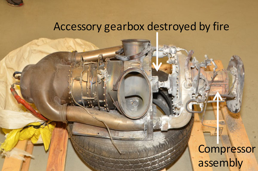
The compressor section of a gas turbine engine takes in ambient air and increases air pressure for use in the combustion process. The compressor assembly consists of an axial compressor, centrifugal compressor/ impellor, compressor case, and diffuser scroll.
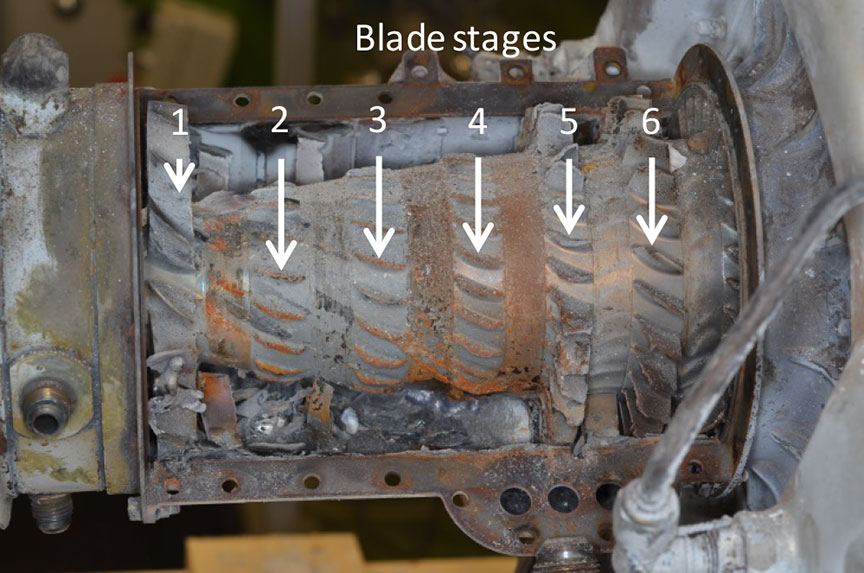
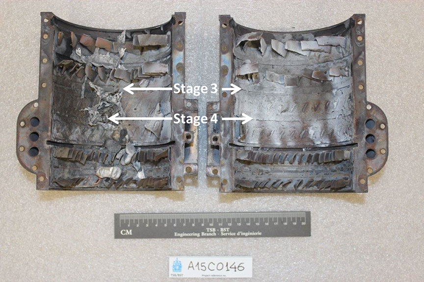
Disassembly of the compressor assembly (part number 6890550, serial number CAC80174) revealed complete failure of stages 2, 3, and 4 of the axial compressor blades. The compressor front support struts did not exhibit any pre-impact anomalies. The stage 1 compressor blades were fully intact. Examination of the compressor front support struts and stage 1 compressor blades did not show any signs of pre-existing erosion/corrosion. The stage 5 and 6 compressor blades showed progressively less damage (Figure 2).
Examination of the compressor assembly revealed that all of the stage 2, 3, and 4 compressor blades had separated near the root. Six of the failed compressor blade roots had partial, readable fracture surfaces. Inspection of the fracture surfaces under the scanning electron microscope revealed overstress failures. The remaining fracture surfaces of the failed compressor blade roots exhibited post-fracture rub and smear.Footnote 12
Examination of the compressor case assembly revealed that the stage 1, 5, and 6 stator vanes were all present but exhibited bending and distortion. All of the stage 3 and 4 stator vanes had fractured near the root (Figure 3). All fractures exhibited post-fracture rub and smear. All but 3 of the stage 2 stator vanes were present. The 3 missing stage 2 stator vanes had fractured near the root. Examination of these fracture surfaces revealed post-fracture rub and smear as well as a layer of high-temperature oxidation. Fracture analysis of the recovered airfoil fragments found further downstream in the engine were inconclusive because of smearing and secondary impact damage.
A review of TC Civil Aviation's Service Difficulty Report database (which, in addition to Canadian data, includes data from the U.S. Federal Aviation Administration and the Australian Civil Aviation Safety Authority) revealed that, in the past 10 years, there have been 13 AllisonFootnote 13 250-C20, C20B, and C20J compressor failures (fracture or excessive wear) that could not clearly be attributed to foreign object damage.
Compressor assembly overhaul and maintenance
The term "overhaul" is defined as a restoration process that includes the disassembly, inspection, repair, or replacement of parts, followed by the reassembly, adjustment, refinishing, and testing of an aeronautical product, and that ensures that the aeronautical product is in complete conformity with the service tolerances specified in the applicable instructions for continued airworthiness.Footnote 14 Aircraft components, such as the engine, are continuously subjected to extremely harsh operating conditions that can affect their structural integrity by inducing wear and fatigue. Through experience and research, manufacturers have established maximum hours between overhauls; compliance with these time periods greatly reduces the likelihood that the component will fail.
Rolls Royce's maintenance practices recommend that the compressor assembly be overhauled at 3500-hour intervals, commonly referred to as the "time between overhaul." The compressor assembly is also subject to an inspection of the compressor case, stator vanes, and compressor blades at 1750-hour intervals. A review of the maintenance records revealed that the compressor in the occurrence helicopter had received the required 1750-hour inspection in March 2012, and no defects were noted. At the time of the occurrence, the subject compressor had a total of 3453 hours of service.
The helicopter had accumulated approximately 570 hours in a salt air environment within the first year following the 1750-hour compressor inspection. Most of the 2.5 years of service before the occurrence were spent further inland.
Operation in a salt air environment, which Rolls-Royce considers to be a corrosive environment, can lead to premature erosion/corrosion of the compressor components. Rolls-Royce Commercial Service Letter (CSL) 1172, Compressor Case, Blade and Vane Erosion/Corrosion Inspection,Footnote 15 and CSL 1135, Contamination Removal (Water Rinse) Instructions Using Water Only,Footnote 16 recommend that operators conduct inspections after a reduced interval of 300 hours and daily fresh-water rinses when operating in an erosive/corrosive environment.
A CSL provides information and recommended maintenance practices that will improve the safety of the aircraft or component and increase its service life. There is no regulatory requirement to follow the recommended practices outlined in a stand-alone CSL. However, operators are required to follow their Maintenance Schedule Approval (MSA). Oceanview's TC-approved MSA for the Hughes 369D states that the company shall comply with all Rolls-Royce 250-C20 series commercial engine bulletins and service letters. The investigation determined that Oceanview had not conducted the reduced-interval inspections and fresh-water rinses, as outlined in CSLs 1172 and 1135 and as required by the company's TC-approved MSA, while the helicopter was operated in a salt air environment.
Emergency locator transmitter
The helicopter was equipped with a 406 AF-H emergency locator transmitter (ELT). The ELT activated on impact, and the signal was received by the Joint Rescue Coordination Centre in Trenton, Ontario. The ELT signal was lost soon after the impact owing to the post-impact fire. The Joint Rescue Coordination Centre did not dispatch any equipment.
TSB laboratory reports
The TSB completed the following laboratory reports in support of this investigation:
- LP0257/2015 – N2 and Rotor RPM Gauge Examination
- LP0264/2015 – Examination of Compressor Assembly and Combustion Case
- LP0278/2015 – Video Analysis
Analysis
General
Records indicate that the pilot was certified and qualified for the flight in accordance with existing regulations. The investigation concluded that pilot fatigue did not play a role in the accident. As well, the weather conditions at the time were not considered to be a factor in this accident.
Before takeoff for the occurrence flight, there were no known technical difficulties with the helicopter. It was also determined that the helicopter's airframe and flight control systems did not contribute to the occurrence. The analysis will focus on the helicopter's powerplant, engine failure during a hover, the accident scenario, and survivability.
Powerplant (engine)
The yellow flame and puff of black smoke seen in the video are indicative of an engine failure. However, a definitive cause for the failure of the compressor assembly could not be determined because of secondary damage (post-fracture smear and rub).
Secondary damage of the compressor assembly and airfoil fragments found further downstream of the compressor section suggest that the engine was still running a short time after the initial compressor failure. Lack of damage to the front support struts or to the stage 1 compressor blades suggests that the engine did not ingest any foreign objects. Compressor damage began with the stage 2 compressor blades. When considering the flow of air during compressor operation, the damage would progress downstream from the initial failure location.
The progression of damage suggests that the initial failure was located either in the stage 2 compressor blade or the stage 2 stator vanes. Because the stage 2 compressor blades were completely destroyed and there was no damage upstream, it is considered likely that the lead event was the failure of a stage 2 compressor blade, resulting in a loss of engine power.
A second, and less likely, scenario involves the failure of a stage 2 stator vane, which would have been deflected forward into the path of the stage 2 compressor blades, resulting in the fracture of the compressor blades and in damage cascading downstream.
Compressor assembly overhaul and maintenance
The compressor failed before its prescribed overhaul period had elapsed. The compressor had accumulated a total of 3453 hours and, at the time of the occurrence, had 47 hours left before its next recommended overhaul.
The occurrence aircraft's compressor was subject to routine visual inspections during scheduled maintenance, with no anomalies noted. In addition, the aircraft was equipped with an inlet barrier filter system to prevent foreign objects from being ingested by the engine. The compressor inlet, the front support struts, and the stage 1 blades did not exhibit any erosion/corrosion or any foreign object damage, suggesting that erosion/corrosion likely did not affect the other compressor assembly components. The inlet barrier filter system significantly reduced the possibility of blade erosion/corrosion and eliminated any foreign object damage to the compressor blade. Therefore, it is highly unlikely that erosion/corrosion or damage caused by foreign object ingestion contributed to the compressor failure.
It was determined that the lead event was likely the failure of a stage 2 compressor blade; therefore, it is likely that the failed compressor blade was subject to fatigue and eventual overload failure before the prescribed overhaul period had elapsed; research suggests that this sort of failure is rare.
The investigation also concluded that, while not contributory in this occurrence, the reduced-interval erosion/corrosion inspection and daily fresh-water rinses of the compressor were not completed as recommended by the engine manufacturer. If operators do not follow manufacturer-recommended procedures when operating in an erosive/corrosive environment, there is an increased risk of an undetected and premature failure of the compressor.
Single-engine helicopter hover operation
Because the operation of a helicopter always includes a state of hover, the rotorcraft flight manual contains a Height Velocity Diagram that indicates combinations of airspeed and altitude that should be avoided. Because a hover cannot be avoided during helicopter operation, the airspeed and altitude combinations are listed in the Performance Data section rather than the Limitations section of the rotorcraft flight manual.
The investigation determined that the helicopter was conducting aerial work operations within the cross-hatched region of the Height Velocity Diagram (Figure 1). The engine failure occurred while the helicopter was in a hover at an altitude from which a successful autorotation was unlikely. If a single-engine helicopter is operated within the confines of the cross-hatched region of the Height Velocity Diagram, the likelihood of a successful autorotation after an engine failure is significantly reduced, increasing the risk of injury or death.
Accident scenario
For the Hughes 369D helicopter to achieve a successful autorotation from a state of hover with no airspeed, required conditions include having a minimum altitude of 500 feet above ground level and then immediately transitioning into forward flight to maintain the rotor energy required to slow down the helicopter's rate of descent.
During the marker ball installation, the helicopter was hovering at an approximate altitude of 325 feet with very little wind. While the helicopter was in the hover, the engine lost power and the pilot then backed up the helicopter to avoid contact with the shield wire and cables below. Without engine power, the helicopter's continued flight depended on the energy remaining in the rotor disc and on transitioning to forward flight. In this occurrence, the pilot had to avoid power lines and could not immediately transition into forward flight. A significant amount of rotor energy was expended while pulling back, and the helicopter began to descend. There was insufficient altitude to conduct a successful autorotation, and the helicopter collided with the terrain.
Survivability
The accident occurred on an uninhabited island, which resulted in a delayed response to the accident. By the time first responders arrived at the site, the helicopter and surrounding vegetation were engulfed by flames.
The rate of descent, calculated by analysis of the video, would have resulted in a g force of 139 to 208 on impact. Possible attempts by the pilot to arrest the rate of descent before impact may have reduced impact forces; however, they remained above the threshold for survivability. The g forces sustained on impact were also well outside the structural limitations of the helicopter and resulted in the rupture of the fuel cell and a post-impact fire. It was determined that the accident was not survivable.
Findings
Findings as to causes and contributing factors
- It is likely that a stage 2 compressor blade was subject to fatigue and eventual overload failure, resulting in a loss of engine power.
- The engine failure occurred while the helicopter was in a hover. There was insufficient altitude to conduct a successful autorotation, and the helicopter collided with the terrain.
Findings as to risk
- If a single-engine helicopter is operated within the confines of the cross-hatched region of the Height Velocity Diagram, the likelihood of a successful autorotation after an engine failure is significantly reduced, increasing the risk of injury or death.
- If operators do not follow manufacturer-recommended procedures when operating in an erosive/corrosive environment, there is an increased risk of an undetected and premature failure of the compressor.
Other findings
- The compressor failed before its prescribed overhaul period had elapsed.
- The inlet barrier filter system significantly reduced the possibility of blade erosion/corrosion and eliminated any foreign object damage to the compressor blade.
Safety action
Safety action taken
Oceanview Helicopters Ltd.
Oceanview Helicopters Ltd. voluntarily suspended, and has not yet resumed, external platform worker operations.
SaskPower
SaskPower began to implement a Helicopter Safety Program at the beginning of 2016. According to the company, action items accomplished by the program included the following:
- basic helicopter safety training for applicable employees,
- utility flight operations training (provided by contractor) for applicable employees,
- long-lining certification training for applicable employees,
- development and implementation of the following standard operating procedures to be used by SaskPower employees and contractors:
- Helicopter Orientation – Transportation of Personnel
- Helicopter Long Line Operations,
- complete renewal of the procurement requirements for helicopter operators for SaskPower, including stringent safety and training requirements, and
- the recruitment of an Aviation Operations Specialist, who will be responsible for
- the development and oversight of a process for flight booking and approval for emergent and non-emergent work for both employees and contractors, and
- the development of aviation-related policies and procedures for SaskPower. This will also include the development of a guide to help select the type of aircraft to use for each work procedure. This action item directly relates to reducing the operation of single-engine helicopters in a prolonged hover.
Forbes Bros. Ltd.
Forbes Bros. Ltd. reported that it had taken the following actions as part of its ongoing efforts to continually improve its health and safety management system:
- reviewed Forbes Bros. Ltd. helicopter operation standards,
- adopted the Helicopter Association of Canada Pre-Flight Risk Assessment best practice as a requirement for all Forbes Bros. Ltd. helicopter vendors,
- engaged third-party aviation safety experts to assist in evaluating Forbes Bros. Ltd. helicopter practices.
This report concludes the Transportation Safety Board's investigation into this occurrence. the Board authorized the release of this report on . It was officially released on .