Loss of control during hydraulic pressure failure training
Eurocopter AS350 BA Helicopter, C-GPHN
Héli-Excel inc.
Sept-Îles Airport, Quebec
The Transportation Safety Board of Canada (TSB) investigated this occurrence for the purpose of advancing transportation safety. It is not the function of the Board to assign fault or determine civil or criminal liability. This report is not created for use in the context of legal, disciplinary or other proceedings. See Ownership and use of content. Masculine pronouns and position titles may be used to signify all genders to comply with the Canadian Transportation Accident Investigation and Safety Board Act (S.C. 1989, c. 3).
Summary
On 03 February 2013, at 0853 Eastern Standard Time, the Eurocopter AS350 BA (serial number 1251, registration C-GPHN), operated by Héli-Excel inc., departed for a training flight from the company base northwest of the Sept-Îles Airport, Quebec, with a flight instructor and 2 pilots in training on board. After practising various types of landings in unprepared areas, the aircraft headed to the Sept-Îles Airport to conduct engine failure drills at the hover at the threshold of Runway 27.
At 0954, the aircraft departed from the threshold of Runway 27 to carry out hydraulic failure drills on Runway 31. During the fourth drill, the flight instructor flew a short pattern at low altitude and low speed without hydraulic pressure assistance. In the moments following the start of the final approach, the cyclic stick moved sharply forward and to the left. The flight instructor grabbed the cyclic stick in an attempt to re-establish level flight, since the helicopter was quickly banking to the left in a nose-down attitude. The main rotor blades struck the runway, and the aircraft came to rest on its left side. The helicopter was heavily damaged by the impact, but no fire broke out. The flight instructor sustained serious injuries, while the other 2 pilots sustained minor injuries. The emergency locator transmitter activated during the occurrence.
Factual information
1.1 History of the flight
On the morning of 03 February 2013, the 3 pilots conducted a visual inspection of the helicopter; no anomalies were detected in the hydraulic system components. They then completed the pre-flight checklist. The “Accumulators check” and “Hydraulic pressure isolation check” did not reveal any malfunction in the hydraulic system.
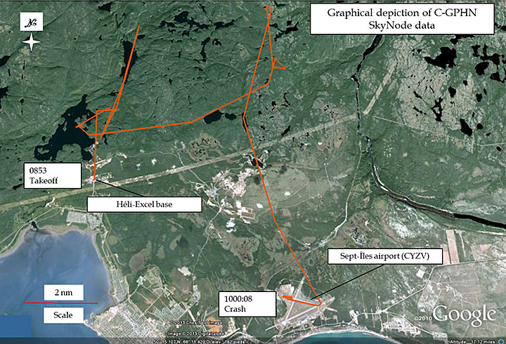
At 0853,Footnote 1 C-GPHN departed from the Héli-Excel inc. (Héli-Excel) base in Sept-Îles, Quebec, for a training flight. The flight instructor was in the left seat, one of the pilots in training was in the right seat, and the other pilot was in seat 1B behind the flight instructor, as an observer. The first 50 minutes of the flight took place north of the Sept-Îles Airport (CYZV), where various types of landings in unprepared areas were conducted (Figure 1). Around 0937, the aircraft headed to the Sept-Îles Airport to conduct drills for engine failure at hover and for hydraulic system failures.
At 0954, after completing drills for engine failure at the hover at the threshold of Runway 27, the helicopter took off to carry out hydraulic failure drills on Runway 31. Shortly after takeoff, the flight instructor engaged the HYD TEST switch. The horn sounded; the pilot in training saw the HYD light illuminate and confirmed the hydraulic failure. The pilot in training did not notice any flight control loads and set the indicated airspeed at between 40 and 60 knots. After the flight instructor turned the HYD TEST switch to the OFF position, the pilot in training pushed the HYD CUT OFF switch at which point the flight controls stiffened. While close to the ground, the aircraft slowed to the point where the pilot in training felt that the loads on the flight controls prevented him from controling the aircraft to make a safe landing.
The flight instructor took over the controls and flew a tight left pattern at low altitude and low speed without hydraulic pressure assistance. He showed the pilot in training the technique for a landing in manual mode, i.e. without hydraulic pressure assistance. The flight instructor landed and stopped the aircraft on the runway without difficulty.
The flight instructor took off and, again with the flight controls in manual mode, flew a tight left pattern at low speed and low altitude. When the aircraft was established on final approach, the pilot in training took over the controls. He made a no-hover landing at a low translation speed of about 10 knots on the icy runway. Since the pilot in training could not stop the helicopter on the ground, the flight instructor took over the controls at the end of the runway.
At 0959, the flight instructor took off in manual mode and again flew a tight left pattern at low speed and low altitude. At the end of the base leg, at the beginning of the final approach, the helicopter momentarily reached a level attitude. Just before the flight instructor handed the controls to the student pilot, the helicopter banked slightly to the left and then quickly rolled to the left in a nose-down attitude, and the main rotor struck the runway.
1.2 Injuries to persons
| Injuries | Crew members | Passengers | Other persons | Total |
|---|---|---|---|---|
| Fatal | 0 | 0 | 0 | 0 |
| Serious | 1 | 0 | 0 | 1 |
| Minor/None | 1 | 1 | 0 | 2 |
| Total | 2 | 1 | 0 | 3 |
1.3 Damage to aircraft
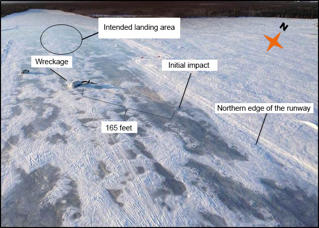
The aircraft struck the ground in a nose-down attitude of about 45° and a left bank angle of about 100°. The first point of impact was near the northern edge of Runway 13/31 (Figure 2). The main rotor blades struck the runway first, followed by the nose of the helicopter. The aircraft slid approximately 165 feet on its left side toward the centre of the runway before coming to a stop on Runway 13/31 about 1000 feet from the threshold of Runway 13.
The collision with the ground caused major damage to the aircraft. The front part of the aircraft, including the nose, windshield, canopies and instrument panel, was torn off. The 2 pilot seats separated from their anchors. The impact caused the tail boom to bend upward and to the left; it sustained an almost full-circumference fracture about 24 inches in front of the horizontal stabilizer. The top of the fuel tank was cracked along the left side from front to rear. The 2 tail rotor blades were not damaged. The engine was still running after the crash. The observer pilot seated at the rear of the cabin had to pull the FUEL SHUT OFF VALVE lever to shut it off.
1.4 Other damage
Over 300 litres of fuel spilled on the runway.
1.5 Personnel information
The flight instructor holds a commercial pilot licence delivered in 2000. He has also been type-endorsed on the AS350 since 2002. At the time of the accident, the pilot had accumulated over 3000 flight hours on type. In 2008, the pilot started providing training on the AS350. In 2012, he was hired as a pilot by Héli-Excel.
In early 2013, Héli-Excel's chief pilot provided him with flight training so that he could become a company flight instructor. The training involved flight drills in normal and emergency situations. After demonstrating his practical skills and theoretical knowledge, the pilot was approved by Héli-Excel's chief pilot as a flight instructor.
The 2 pilots on board the aircraft were the first pilots that the flight instructor was training for the company. The training flight was part of recurrent training and pilot proficiency check (PPC).
The flight instructor was not qualified as such and was not a Transport Canada-approved check pilot; this is not required by the Canadian Aviation Regulations (CARs).
The 2 pilots in training had obtained their commercial pilot licences in 2011. The pilot in the right-hand seat was hired by Héli-Excel in August 2012. He had received his AS350 rating in May 2012. His experience on this type was limited to training received with another carrier and a few flights. He had accumulated less than 200 flight hours on an helicopter.
The observer pilot had been hired by Héli-Excel in January 2013 and had no AS350 rating.
1.6 Aircraft information
1.6.1 General
| Manufacturer | Eurocopter |
|---|---|
| Type and model | AS350 BA |
| Year of manufacture | 1980 |
| Serial number | 1251 |
| Certificate of airworthiness | Valid |
| Airframe time | 10 017.6 |
| Engine | Allied Signal LTS101-600A-3A |
| Maximum allowable take-off weight | 4961 pounds |
| Recommended fuel type(s) | Jet fuel |
| Fuel type used | Jet fuel |
1.6.2 Conversion history
1.6.2.1 General
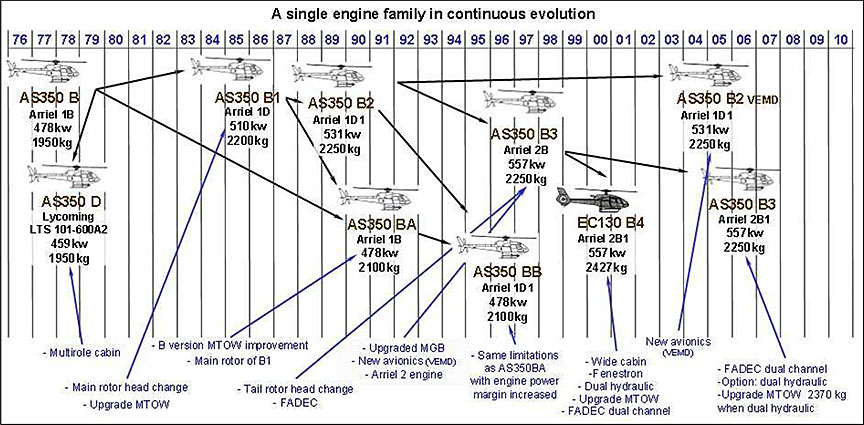
C-GPHN was originally manufactured as an AS350 D in 1980 by Aérospatiale (Figure 3). On 16 May 2001, the aircraft was converted into an AS350 BA as per Eurocopter service bulletins. At the same time, modifications were made as per Apex Aerospace, Inc.'s Transport Canada-approved SH02-15 supplemental type certification (STC). These changes reduced fuel consumption and increased the helicopter's internal gross weight to that of the AS350 B2, i.e. 2250 kg (4961 pounds). Operators commonly refer to the AS350 BAs that have been modified as per the Apex SH02-15 STC as AS350 BA+ to distinguish them from the other models.
1.6.2.2 Apex Aerospace SH02-15 supplemental type certification
Given that the AS350 BA+ and the AS350 B2 have the same internal gross weight, the drive train systems of models BA, BA+ and B2 were compared. Similarities were noted, except that the AS350 B2 is equipped with a yaw channel load compensator to counter the high forces on the pedals during a hydraulic failure. It was also noted that the torque limits and shaft horsepower of the BA and BA+ are similar, whereas those of the B2 are higher
Given that the torque limits of the AS350 BA and AS350 BA+ are the same, it can be concluded that the absence of a load compensator on the BA did not affect the handling characteristics of C-GPHN when the hydraulic system was depressurized.
| Engine torque limits | Internal gross weight | External gross weight | Shaft horsepower maximum continuous/ take-off | |
|---|---|---|---|---|
| BA+ | 83%, 88% | 2250 kg | 2250 kg | 590/650 |
| BA | 83%, 88% | 2100 kg | 2100 kg | 590/641 |
| B2 | 94%, 100%, 107% | 2250 kg | 2500 kg | 625/712 |
1.6.3 Engine information
The Allied Signals LTS101-600A-3A engine was not damaged. No engine malfunction was observed during the flight. The overload failure of the main- and tail-rotor shafts shows that the engine was producing power at the time of the accident. The engine logs indicate that it was maintained and serviced in accordance with existing Canadian regulations and approved procedures. Engine performance and mechanical malfunction were not considered to have been contributing factors in the accident.
1.6.4 Maintenance
The maintenance records show that the helicopter was certified, equipped and maintained in accordance with existing regulations and approved procedures. The helicopter had flown 65.5 hours since its last 100-hour inspection. No pre-flight malfunction was reported or deferred.
1.6.5 Weight and centre of gravity
It is estimated that the helicopter weighed 4150 pounds at the time of the accident. The aircraft's weight and centre of gravity were within the limits prescribed in the Transport Canada-approved rotorcraft flight manual (RFM) and did not play a role in the accident.
1.6.6 Flight control hydraulic system
1.6.6.1 General
The flight controls are assisted by a single hydraulic system that reduces pilot workload during flight and at speeds where loads on the manual flight controls are excessive.
1.6.6.2 Hydraulic system components
The hydraulic system is pressurized by a pump driven by the input shaft of the main transmission gearbox, through a flat strap.
The helicopter is equipped with 4 servoactuators, 3 of which actuate the stationary swashplate: 1 servoactuator for pitch control, and 2 servoactuators for roll control (Appendix B). The fourth servoactuator is in the tail rotor. In order to offset excessive loads in the event of a hydraulic system failure at high speed, a safety unit consisting of an accumulator, a non-return valve and a solenoid valve was installed on each servoactuator. The hydraulic pressure provided by the accumulators allows the pilot to safely reduce the airspeed to a value at which the manual control forces are manageable without hydraulic pressure assistance. The AS350 BA is not equipped with a control channel load compensator on the tail rotor.
The pressure regulator incorporates a pressure switch for low hydraulic pressure and a test solenoid valve. When the pressure switch senses that the hydraulic system pressure drops below 30 bars, the red hydraulic system warning light (HYD) illuminates on the control panel and the horn sounds. The same horn also provides warning of low rotor speed.
1.6.6.3 Hydraulic system controls and monitoring
1.6.6.3.1 General
The hydraulic system is controlled by the HYD CUT OFF [hydraulic system cut-off] switch, mounted on the collective stick of the right-hand seat, and by the HYD TEST [hydraulic system test] switch, mounted on the centre console. The left-hand seat flight controls used by a co-pilot or a flight instructor are removable and the collective stick is not equipped with a HYD CUT OFF button.
1.6.6.3.2 The HYD CUT OFF switch
The HYD CUT OFF switch is a toggle switch with 2 positions – ON and OFF, and is normally set to the ON (forward) position during flight. When the switch is in the OFF position, the hydraulic system becomes depressurized and the main rotor accumulators become depressurized simultaneously in order to prevent asymmetric depletion. Asymmetric depletion of the accumulators can generate asymmetric forces that would make controlling the aircraft difficult. Consequently, the pilot must activate the HYD CUT OFF switch either in the event of a hydraulic system failure or during a hydraulic malfunction simulation once the pilot has reached safety speed, i.e. the speed at which the manual control forces are such that it is possible to maintain control of the helicopter. However, the tail rotor servoactuator is also depressurized by the HYD CUT OFF switch; therefore, the tail rotor servoactuator does not maintain its hydraulic pressure during a simulated failure. If hydraulic pressure is available in the system, the pilot can instantly restore the hydraulic pressure of the servoactuators and repressurize the accumulators by placing the HYD CUT OFF switch in the ON position.
1.6.6.3.3 The HYD TEST switch
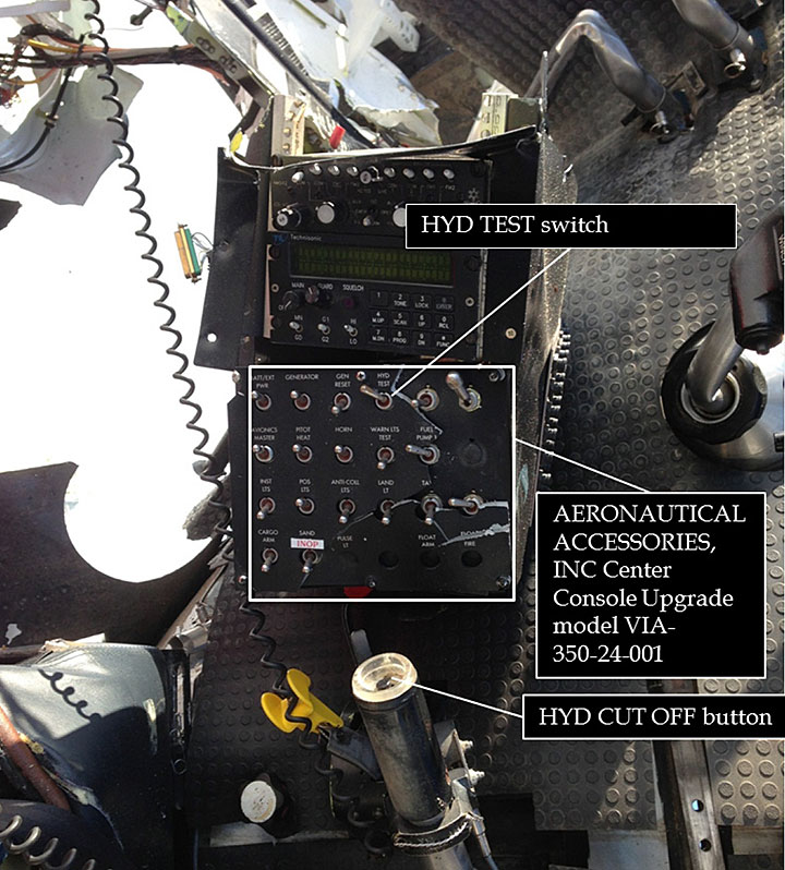
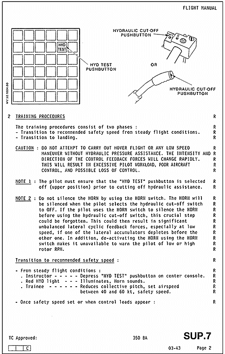
The HYD TEST switch, which is mounted on the centre console (Aeronautical Accessories, Inc. Center Console Update model VIA-350-24-001) between the 2 pilots, has 2 positions. The TEST position (forward position) initiates the hydraulic system test function while the OFF position (aft position) restores normal operation. The centre console certified by the manufacturer uses a 2-position pushbutton for this function: TEST when it is pushed in, and OFF when it is released (see paragraph 1.6.6.4).
The HYD TEST switch is intended primarily to allow the pilot to make sure, before the flight, that the accumulators of the main rotor servoactuators are working properly. The HYD TEST switch is also used to simulate a hydraulic system malfunction during a training flight.
When the switch is in the TEST position, the hydraulic test solenoid valve opens, depressurizing the hydraulic system. As a result of this depressurization, the HYD warning light illuminates and the horn sounds. The accumulators are tested during the pre-flight check by the pilot selecting the HYD TEST switch to TEST and moving the cyclic stick 2 or 3 times on each axis (+/- 10% of the complete range) to verify that there is sufficient hydraulic pressure to ensure that safety speed can be reached after a hydraulic failure.
1.6.4 Centre console
In May 2005, the original centre console (Honeywell Control Unit), which contained the control buttons for the helicopter's various systems, was replaced as per STC No. SR00825NY-D with a Center Console Upgrade model VIA-350-24-001 from Aeronautical Accessories, Inc.
One of the distinguishing features of the new console is that the original latched illuminated pushbuttonsFootnote 2 were replaced by toggle switches.
The HYD TEST switch is located next to other similarly shaped switches (Figure 4). It was determined that the HYD TEST switch can be inadvertently actuated during flight because of its proximity to other switches. In November 2005, Eurocopter issued Service Bulletin SB 67.00.32 which recommended the installation of a retractable guard/cover (protection flap) over the switch on Honeywell centre consoles to prevent the unintentional operation of the HYD TEST switch.
In September 2007, Transport Canada (TC) issued Airworthiness Directive (AD) CF-2007-19, which required that the HYD TEST pushbutton on Honeywell consoles be equipped with a protection flap with a 90-degree opening to reduce exposure to events leading to hydraulic system loss and control difficulties. This AD was replaced by CF-2007-19R1 on 27 November 2008 (Appendix A), which describes the mandatory installation of a more reliable protection flap with a 180-degree opening, as per revision 1 of Eurocopter's Service Bulletin SB 67.00.32 issued on 19 February 2008.
The HYD TEST toggle switch on C-GPHN's Aeronautical Accessories, Inc. centre console is not of a specific shape and is not equipped with a protection flap, or have the “pull-to-unlock” design. Since AD CF-2007-19R1 applies to AS350s equipped with a Honeywell centre console, C-GPHN was not required to comply with the corrective measures set out in the AD.
1.6.6.5 Hydraulic system certification
During initial certification, the aircraft was shown to have adequate handling characteristics in manual control mode. However, the loads were considered excessive at high speed. Consequently, a safety unit consisting of an accumulator, a non-return valve and a solenoid valve was installed on each servoactuator. The hydraulic pressure provided by the accumulators allows the pilot to reduce the airspeed to the safe recommended speed of between 40 and 60 knots before setting the HYD CUT OFF switch to the OFF position. The control forces are deemed manageable within this speed range.
1.6.6.6 Documentation concerning the effort required without hydraulic pressure assistance
1.6.6.6.1 General
TC and Eurocopter recognize the risks associated with operating outside the recommended safety speed range in the event of a hydraulic system failure. In addition, several investigation reportsFootnote 3 on loss of control following depressurization of the AS350 hydraulic system document these risks.
1.6.6.6.2 Transport Canada
In 2003Footnote 4 and 2004,Footnote 5 TC and Eurocopter jointly examined the hydraulics-off handling characteristics of the AS350 B2Footnote 6 in very cold weather. Following these in-flight tests, TC concluded that flight control forces were high at speeds above the safety speed and marginally acceptable within the safety speed range, and that their direction and intensity were very high and unstable in hover flight. TC observed that nowadays these forces would be unacceptable for new helicopter designs.
1.6.6.6.3 Rotorcraft flight manual
The helicopter's RFM, developed by Eurocopter contains sections on limits, procedures and performance requirements for safe use of the aircraft. The RFM approved by the Direction générale de l'aviation civile (DGAC) of France contains the following sections: 2 – Limitations, 3 – Emergency Procedures, 4 – Normal Procedures, 5.1 – Regulatory Performance Data, and RFM supplements. Full compliance with section 2 – Limitations is mandatory for Canadian-registered aircraft.
As in all RFMs, Eurocopter uses the terms CAUTION and NOTE to emphasize important or critical instructions for safe flight. Although not defined in the RFM, the warnings in the RFMs are usually codified as follows:
- WARNING means an operating procedure which could lead to injuries or loss of life if not followed correctly.
- CAUTION means an operating procedure, practice, etc. which could lead to equipment damage or loss if not adhered to strictly.
- NOTE means an operating procedure or condition worthy of mention.
The risk of heavy flight control feedback in the event of a hydraulic system failure is mentioned in sections 3 and 7 of the RFM, and in the RFM supplements:
Section 3 – Emergency Procedures, 3.2 – System Failure, subsection 4 – Hydraulic System Failures:
4.2 Main servo-control slide-valve seizure
- Actuate the [HYD CUT OFF] switch, situated on the collective pitch control lever, to cut off hydraulic pressure. Load feedback will be felt immediately; load feedback may be heavy if the helicopter is flying at high speed:
- collective pitch: 20 kg pitch increase load;
- cyclic: 7 to 4 kg left-hand cyclic load;
- cyclic: 2 to 4 kg forward cyclic load;
- yaw pedals: practically no load in cruising flight.
- Reduce speed to 60 knots (110 km/hr) and proceed as in the case of illumination of the HYD light.
Figure 5 is an excerpt from the procedure in case of illumination of the red HYD light (under Section 3 – Emergency Procedures, 3.3 – Warning-Caution-Advisory Panel and Aural Warning, subsection 2.1 – Red Lights).

Approach and landing
Over a clear and flat area, make a flat final approach, nose into wind. Perform a no-hover/slow run-on landing around 10 knots. Do not hover or taxi without hydraulic pressure assistance.
Section 7 – Description and Systems, 4 – Abnormal Operations, states in part the following:
For loss of hydraulic pressure, at a speed between 40 and 60 knots, the lateral force required to push the cyclic stick to the left is about 4 dekanewtons (daN) (9 pounds). The logitudinal force required to push the cylic stick forward is about 5 daN (11 pounds).
During a no-hover landing at about 10 knots, the pilot could be faced with longitudinal forces of up to 17 daN (37 pounds) for less than 30 seconds with low lateral forces. If the helicopter is hovering, the control load forces change, in both direction and intensity, as the pilot attempts to maintain a steady position. The pilot will exert longitudinal and lateral forces of up to 5 daN (12 pounds), the direction of which could change quickly. This translates into excessive pilot workload and poor helicopter control.
For a failure other than a hydraulic system failure, the maximum forces a pilot should exert on the controls to maintain helicopter attitude are about 15 daN (33 pounds) on the left or right lateral cyclic and 17 daN (37 pounds) on the forward longitudinal cyclic.
1.6.6.7 Transverse flow
When a hovering helicopter begins the transition to level flight, the airflow differs depending on whether it occurs in front of or behind the rotor disk. In the case of the AS350, the rotor rolls to the right. This results in increased lift and upward flapping in front of the disk, as well as decreased lift and downward flapping behind the disk. This phenomenon is known as transverse flow. The pilot must therefore compensate for this phenomenon by moving the cyclic stick to the left to limit roll.
1.6.6.8 Hydraulic pressure failure training
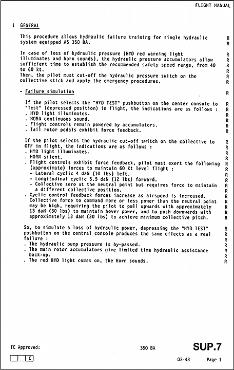
The RFM Supplement 7 (SUP.7), Hydraulic Pressure Failure Training Procedures in Cruise Flight Conditions, describes the procedure for hydraulic failure training in flight (Appendix C). SUP.7 states the measures that the flight instructor and pilot in training must take in the event the HYD light illuminates in order to comply with the emergency procedure set out in the RFM. No environmental limitation other than those stipulated in the RFM, section 2 – Limitations, is mentioned in SUP.7. Hydraulic failure training can be given without wind restriction and in temperatures as low as –40°C.
A hydraulic system failure is simulated in steady flight by activating, in sequential order, the HYD TEST and HYD CUT OFF switches. The training procedure consists of 2 steps:
- The transition between steady flight and the recommended safety speed (40 to 60 knots);
- The landing phase.
First, the flight instructor moves the HYD TEST switch to the TEST position and the pilot in training slows down to the recommended safety speed. The accumulator charge pressurizes the main rotor controls and gives the pilot in training enough time to reach the recommended safety speed. The first step of the training is completed when the flight is stable at a speed between 40 and 60 knots.
Second, when the helicopter is at a stable speed, the flight instructor repressurizes the hydraulic system and recharges the accumulators by placing the HYD TEST switch in the OFF position. The pilot in training then places the HYD CUT OFF switch in the OFF position, and continues flying the aircraft in manual mode. Having these 2 switches in that configuration allows the pilot to turn the hydraulic pressure assistance back on by placing the HYD CUT OFF switch in the ON position during the training drill, if necessary.
Over a clear and flat area, the pilot in training makes a flat final approach, nose into the wind,and performs a no-hover slow landing at about 10 knots. The manufacturer's procedures and warnings are clear and do not allow for any landings other than run-on.
The SUP.7 subsection that describes the procedure for the transition to landing phase notes the possibility, if necessary, of restoring hydraulic pressure during the drill by selecting the HYD CUT OFF switch to ON.
The aircraft's RFM was up to date and contained SUP.7, revision 1, but neither the company nor the flight instructor were aware of SUP.7′s existence.
1.7 Meteorological information
According to the aviation routine weather report (METAR) for Sept-Îles, at the time of the accident, the conditions were as follows:
- calm winds;
- visibility 30 statute miles;
- few clouds at 2000 feet above ground level;
- temperature -21°C and dew point -30°C.
1.8 Aids to navigation
Not applicable.
1.9 Communications
The helicopter radio was operating normally. The aircraft reported no problem before the accident.
1.10 Airport information
The Sept-Îles Airport is certified, operated and maintained by TC. The airport has a flight service station (FSS) operated by NAV CANADA. Its reference altitude is 180 feet above sea level (asl). The airport has 2 runways: Runway 09/27 and Runway 13/31 (Figure 6). The elevation of the Runway 31 threshold is 173 feet asl. At the time of the occurrence, Runway 27 was the active runway.
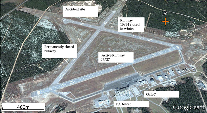
Runway 13/31 had been closed since 31 January 2013. Its paved surface was covered with ice and patches of snow. Communications between the helicopter and the FSS revealed that the crew reported no problems and did not declare an emergency situation before or after the crash.
1.11 Flight recorders
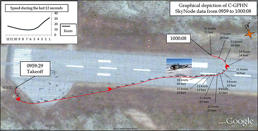
The helicopter was equipped with a SkyNode satellite tracking and data telemetry system.Footnote 7 The system records data from the global positioning system (GPS) that is part of the SkyNode module. The logged data include the time of the recording, geographical coordinates, altitude, groundspeed, aircraft direction, and the messages “Take Off h,” “Landing h,” “Pausing,” and “Start Up.”Footnote 8
The SkyNode memory contained data from 1345:57 UTCFootnote 9 to 1500:08 UTC. The SkyNode recorded data every 2 minutes, except for the last 2 minutes of the flight when data were recorded every second. With these data, the approximate flight path could be reconstructed (Figure 7). The last recording indicates that the helicopter was 39 feet above ground level (agl) at a groundspeed of 32 knots (Figure 8).

1.12 Wreckage and impact information
1.12.1 General
The wreckage was sent to the TSB laboratory in Ottawa, Ontario, where it was examined in the presence of the Bureau d'Enquêtes et d'Analyses pour la sécurité de l'aviation civile (BEA) of France, Eurocopter, and TC. The servoactuators, the hydraulic pump components, the pressure regulator, the accumulators and the hydraulic filter were removed from the aircraft for operating tests at Eurocopter Canada Ltd. in Fort Erie, Ontario, in the presence of the TSB, BEA, Eurocopter, and Héli-Excel. The following observations were made:
- the HYD TEST toggle switch was pushed forward and to the left in the TEST position (Figure 4);
- the HYD CUT OFF pushbutton at the end of the collective stick was set in the CUT OFF position;
- the damages (deformation, failure) observed during examination of the drivetrain were attributable to the accident;
- a continuity and integrity check of the drivetrain revealed that it was intact before the accident;
- no pre-impact deformation or failure was noted in the flight controls.
1.12.2 Examination of hydraulic system harnesses and contacts
The solenoid valves of the servoactuators were operating properly as a group and individually. Electrical continuity of the servoactuators was confirmed. The HYD TEST switch and the HYD CUT OFF switch were operating properly.
No anomaly was observed on the electrical components of the hydraulic system, i.e. the harnesses, contacts, solenoids and switches, that could have led to a malfunction at the time of the occurrence.
1.12.3 Examination of the hydraulic reservoir and hydraulic fluid
No water accumulation was found in the cone of the hydraulic reservoir cap. Analysis of the hydraulic fluid revealed no anomaly that could compromise the proper operation of the hydraulic system.
1.12.4 Examination of the servoactuators
The aircraft was equipped with 4 Dunlop servoactuators. The tests conducted at Eurocopter on the servoactuators, accumulators, solenoid valves, filter and hydraulic pump confirmed that they were functioning properly. However, deviations were noted between some test results and the values specified in the Component Maintenance Manual (CCM). According to Eurocopter, the deviations noted did not have an impact on the operation of these components and could possibly have been caused by the crash.
The servoactuators were then sent to Meggitt Control SystemFootnote 10 in Coventry, Great Britain, where they were examined and tested. The servoactuators were subjected to various tests which showed deviations from the design tolerance range. Three servoactuators exceeded the certification tolerances for extension speeds and 2 servoactuators exceeded the certification tolerances for retraction speeds. The 4 servoactuators operated under hydraulic pressure. According to Meggitt Control System, the test results were typical of servoactuators approaching the end of their operating time between overhauls.
The tests conducted at Eurocopter and Meggit Control System revealed no anomalies in manual mode.
1.12.5 Warning lights
Examination of the light bulb filaments of the warning lights in the annunciator panel revealed either localized or generalized stretching in the HYD, DOORS, F.FILT and M.G.B.T. lights. This stretching is typical of illuminated bulbs.Footnote 11
| Warning light | Failure |
|---|---|
| HYD | Loss of hydraulic pressure or pressure < 30 bars |
| DOORS | 1 or 2 lateral cargo doors open |
| F.FILT | Pre-blockage fuel filter |
| M.G.B.T. | Main gearbox, maximum oil temperature |
The HYD light was illuminated before impact after the pilot in training pressed the HYD CUT OFF switch as part of the hydraulic failure drill. According to the information obtained, no other light was illuminated prior to impact with the ground. Since the engine continued to run after the accident, the warning system remained operational. It was therefore concluded that the DOORS, F.FILT and M.G.B.T. lights illuminated as a result of the damage caused by the accident.
1.12.6 Cockpit seats
During the occurrence, the 2 pilot seats were subjected to upward vertical forces, lateral forces to the left, and forward longitudinal forces. The right-hand seat separated from the floor, while the left-hand seat separated from its box. The lap belts remained attached to the floor and their straps and buckles were intact. The 2 seats failed in overload. The floor under the base of the left-hand seat was severely damaged, which caused the seat to separate from its box. At the time the aircraft was certified, the seats were designed to resist upward vertical acceleration of 1.5 g, downward vertical acceleration of 4.0 g, longitudinal acceleration of 4.0 g, and lateral acceleration of 2.0 g.Footnote 12
The resistance standards have since changed. Seats must now resist upward vertical acceleration of 4.0 g, downward vertical acceleration of 20.0 g, forward longitudinal acceleration of 16.0 g, rear longitudinal acceleration of 1.5 g, and lateral acceleration of 8.0 g.
Airbus Helicopters, the holder of the type certificate, issued a service bulletin (SB 25.00.57) that suggests installing pilot and co-pilot seats with an improved structural design that complies with the new certification requirements.
1.13 Medical and pathological information
Not applicable.
1.14 Fire
There was no fire.
1.15 Survival aspects
1.15.1 General
After the crash, the aircraft came to rest on its left side, and the 2 front seats failed in overload. The 2 pilots in these seats were unconscious. The pilot in the left-hand seat was leaning on the pilot in the right-hand seat. The pilot observer seated in the back unbuckled his seat belt and exited the aircraft through the large hole formed in the roof of the cabin. Once outside the aircraft, he noted that the other 2 pilots were lying motionless in the wreckage and that the engine was still running. He also noticed a large fuel spill. He returned to the aircraft and first had to remove the 2 pilots from their seats to gain access to the fuel shut-off lever. He dragged the pilots, whose clothes were soaked with fuel, several metres away from the wreckage. After shutting off the engine, he administered first aid to the pilots, who regained consciousness a few minutes later. The 3 pilots sustained injuries to the head and face. None of them was wearing a helmet, nor were they required to do so by regulations.
1.15.2 Helmet
Although the CARs do not require helicopter pilots to wear a helmet, the TSB has documented a number of cases where wearing a helmet would likely have reduced or prevented pilot injuries. On 30 October 2009, the TSB issued Aviation Safety Advisory A09A0016-D2-A1 – Low Usage of Head Protection by Helicopter Pilots, emphasizing that without ongoing and clear communication promoting the benefits of using head protection, helicopter pilots will continue to operate without a helmet, increasing the risk of head injury and consequent inability to provide necessary assistance to crew or passengers.
1.15.3 Emergency services
The Sept-Îles Airport does not provide aircraft rescue and firefighting (ARFF) services.Footnote 13 The fire department of the city of Sept-Îles provides firefighting services in the event of an accident or incident at the airport. Response time is at least 15 minutes. Fires in the city of Sept-Îles have priority.
The crash site was more than 4000 feet away from active Runway 09/27. The airport remained open after the accident, meaning that aircraft could take off and land.
1.15.4 Emergency locator transmitter
The aircraft was equipped with a KANNAD emergency locator transmitter (ELT), model 406AF-COMPACT, serial number 259637, that can broadcast on frequencies 121.5 MHz and 406 MHz. The ELT was not damaged and it activated following the impact.
1.15.5 Emergency response plan of the Sept-Îles Airport operator
The operator of an airport must develop and maintain an emergency response plan.Footnote 14 In 2000, the Sept-Îles Airport operator adopted an emergency response plan identifying the roles and responsibilities of each responder in the event of, among other things, an aircraft accident at the airport.
In the event of an accident at the airport, the FSS immediately contacts the CAUREQ (Centre d'appel d'urgence des régions de l'Est du Québec ) by dialling 911. The CAUREQ notifies the fire department, the Sûreté du Québec (SQ) and ambulance services, which in turn notify the Sept-Îles Health and Social Services Centre, the hospital, and lastly, the airport manager or duty manager.
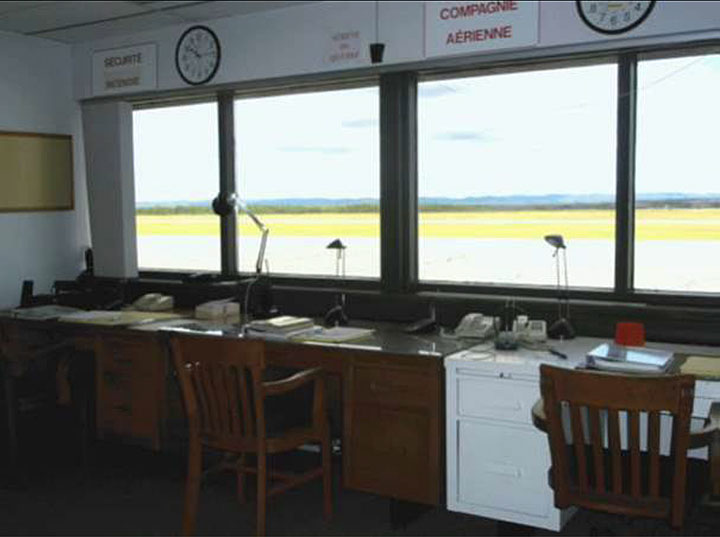
The airport manager or duty manager, who is not necessarily present at the airport, immediately heads to the emergency operations centre (EOC) and notifies the relevant response units. The EOC, where representatives of the response units gather, contains communication, information and recording equipment and becomes the communications centre (Photo 1). The responders use various radio frequencies to communicate with each other. The EOC also remotely controls gate 7, located between the terminal and the airport multi-purpose building.Footnote 15 In an emergency, the gate is identified by a flashing red light, and the SQ controls its access. To ensure that the EOC is opened as quickly as possible, the airport operator had provided some first responders with a key to the premises. However, at the time of the occurrence, some of them either did not know they had a key or had lost it.
The airport manager or duty manager is responsible for, among other things, coordinating activities in the EOC and providing any assistance required by the operations commander at the accident site. He is also responsible for managing the airport during the emergency and making decisions concerning its operation.
The airside is protected by a security fence and access is mainly controlled by 2 magnetic-card activated gates. The distribution of these magnetic cards is controlled. Users are NAV CANADA and TC personnel, as well as others who have an airside vehicle operator's permit (AVOP).
Airside driving is regulated by AVOP standards, and persons without an AVOP must be escorted.
1.15.6 Emergency response
At 1000, the NAV CANADA FSS specialist on dutyFootnote 16 observed the aircraft strike the ground; he did not receive any distress call from the helicopter either before or after the impact. He immediately dialled 911 and reported the accident to the CAUREQ, which alerted the fire department, SQ and ambulance services, but did not inform airport officials of the emergency situation.
Given that the crash site was more than 4000 feet away from the active runway, Runway 09/27, the airport remained open after the accident, meaning that aircraft were able to continue taking off and landing during the emergency response.
At 1005, by telephone,Footnote 17 the FSS dispatched to the accident site an ambulance, which was on the apron for a medical evacuation.
Between 1006 and 1015, 2 SQ vehicles, 2 ambulances, and Sept-Îles fire department officials arrived at gate 7. The SQ officer in charge went to the FSS tower to coordinate the activities of the ground crews.
Around 1015, an employee from a medical carrier opened gate 7. The responders' vehicles immediately started driving on Runway 09/27 unescorted and without authorization or means of communicating with the FSS. They believed the airport was closed to air traffic. Once they were on the runway, the responders became disoriented; although they could see the wreckage and the ambulance, they did not know how to reach them. Meanwhile, a de Havilland DHC-8, operated by Air Canada Express, was making its final approach for the runway and had to pull up after being notified by the FSS specialist of a runway incursion.
At 1028, 2 fire trucks from the Sept-Îles fire department and the airport fire truck arrived at the accident site. At 1031, the 2 pilots who had been sitting in the front seats were en route to the hospital. At 1037, the airport duty manager was notified of the accident by the airfield supervisor. He arrived at the crash site at 1045. At 1145, the duty manager opened the EOC and activated the emergency response plan. At 1249, the emergency response ended and the EOC was closed.
1.15.7 Post-occurrence debriefing meeting
The responders held 2 debriefings after the accident. During these meetings, they identified the following irregularities in relation to the emergency response plan:
- The first responders did not have their keys to access the EOC.
- The CAUREQ did not inform the airport manager or the duty manager of the emergency.
- The EOC was opened 1 hour and 45 minutes after the accident.
- A responder opened gate 7 without authorization.
- Response vehicles drove unescorted in the airport's manoeuvring areas and without authorization or means of communicating with the FSS.
1.15.8 Emergency drill at the Sept-Îles Airport
The Sept-Îles Airport must test its emergency response plan by conducting full-scale drills at least every 4 years.Footnote 18 In addition, the airport operator must hold table-top exercises every year that full-scale drills are not held.
The last full-scale drill held at the Sept-Îles Airport before the accident was conducted on 09 October 2008. The drill consisted of a simulated aircraft crash at the airport. Based on the minutes of the debriefing, the results of the drill were generally satisfactory.
However, the very nature of an emergency drill is such that some shortcomings are always identified. The presence of a large number of responders in the FSS tower impeded the specialist's work. It was also found that there was insufficient personnel at gate 7 to escort responders to the accident site.
1.16 Tests and research
1.16.1 TSB laboratory reports
The TSB completed the following laboratory reports in support of this investigation:
- LP022/2013 – Download of SkyNode Transmitter
- LP032/2013 – Seat Examination
- LP035/2013 – Hydraulic System Examination
- LP052/2013 – Flight Path Analysis
- LP053/2013 – GPS Analysis
1.17 Organizational and management information
1.17.1 General
Héli-Excel holds a valid operating certificate and its base is located about 7 nautical miles (nm) northwest of the Sept-Îles Airport. At the time of the accident, Héli-Excel operated a fleet of 20 helicopters, comprising Bell 205, Bell 206, Bell 206L, Bell 214B-1, Eurocopter AS350 B, BA,B2, D, and Eurocopter AS355-F. These aircraft are operated according to Subparts 2 and 3 of Part VII of the CARs. The occurrence flight was operated under Subpart 3, Air Taxi Operations.
Héli-Excel uses a safety management system (SMS), although it is not required to do so by the CARs. The program validation inspection (PVI) conducted by TC in February 2010 found no non-compliance with any operational control aspect since Héli-Excel met all the measurement criteria. In fact, the company earned a high score because it met 5 of the 8 criteria required for a perfect score.
1.17.2 Flight instructor training
At the time of the accident, the company provided pilot training. The chief pilotFootnote 19 and 2 flight instructors reporting to him were delivering annual type training and specialized training in accordance with the company's training program.Footnote 20
Flight instructors were not required to have an instructor's rating. They were, however, required to hold a commercial pilot licence and be type-endorsed for AS350 to provide flight instruction. As stipulated in the CARs, they also had to show that they knew the content of the helicopter's RFM, of the company check pilot manual, and of the company's operations and training manuals.
The flight instructors' training and qualifications were in accordance with the CARsFootnote 21 and Héli-Excel had not set requirements other than those in the CARs.
The company selected flight instructor candidates on the basis of their experience and flight skills. The chief pilot then reviewed the aircraft's in-flight emergency procedures with them. The candidates were appointed flight instructors after demonstrating their ability to correctly execute the procedures in the aircraft's RFM.
Together with the chief pilot, the flight instructors were responsible for implementing and promoting the flying standards and techniques that flight crews must follow during operational flights and with which compliance must be shown during initial and periodic checks. They were also responsible for delivering flight training to all flight crews, in accordance with the training program approved for the type of assigned aircraft.Footnote 22
The company encouraged its pilots in training to observe the training drills of other pilots on board the aircraft. This practice was considered helpful to the pilots' learning since it allowed them to observe first-hand normal, abnormal and emergency procedures being carried out. According to TC, this practice contravened the CARs,Footnote 23 which stipulate that only individuals essential to the flight can be on board during a training flight. Since the occurrence, the company no longer authorizes pilots, other than the flight instructor and student pilot, to be on board an aircraft during a training flight.
1.17.3 Héli-Excel Pilot Training on AS350
According to the company's operations manual, the purpose of technical ground training and flight training is to teach the crew about the aircraft's systems and the procedures to follow in normal, abnormal and emergency situations. In this occurrence, the pilot in training had just completed his technical ground training on the AS350 and knew the procedure for hydraulic failure as well as the risks associated with flying without hydraulic pressure assistance.
1.17.4 Héli-Excel's hydraulic failure training
The company was not aware that Eurocopter had published a flight training procedure for hydraulic pressure loss which could be found in SUP.7. The company's training procedure was in fact similar to and complied with the one in SUP.7, except that flight instructors did not know that pressurizing the hydraulic system was permitted in flight. Some pilots reported that they believed that pressurizing the hydraulic system in flight, coupled with the inherent instability of a helicopter and the forces on the controls, would lead to a loss of control as a result of excessive corrections.
When a pilot in training was unable land because of difficulty controlling the aircraft, the company expected the flight instructor to take over the controls and land the aircraft. If landing was impossible, the flight instructor was to pull up and reach safety speed before completing a pattern and landing without hydraulic pressure assistance.
With regards to loss of hydraulic pressure training, the investigation found minor procedural differences among companies and in relation to SUP.7. At one large AS350 operator, the hydraulic failure drill always begins halfway through the downwind pattern and invariably ends with a landing. After landing, the hydraulic system is repressurized before conducting the drill again. As well, the manipulation sequence differs from the procedure described in SUP.7; after pressing the HYD TEST pushbutton, the pilot in training pushes the HYD CUT OFF switch before restoring pressure with the HYD TEST button. Flight instructors find that this method more closely simulates a real-life hydraulic failure than the one suggested in SUP.7. However, activating the HYD CUT OFF switch before restoring pressure in the hydraulic system using the HYD TEST button does not recharge the tail rotor accumulator on a helicopter equipped with a compensator.
The investigation also revealed that some flight instructors were not fully aware of the risks associated with manoeuvres at low altitude and in hover without hydraulic pressure assistance. Flight instructors tend to believe that loss of control incidents stem from mechanical anomalies rather than from the handling characteristics of the AS350.
1.17.5 Flight instructor's experience with hydraulic failure
During his career, both as a pilot and as an instructor, the flight instructor had always encountered manageable forces during hydraulic failure drills. Moreover, during their hydraulic failure training, pilots trained on the earlier models of the AS350Footnote 24 experienced less feedback loads than those generated by later models because the earlier models had lighter rotor feedback loads.
Additional information
Not applicable.
Useful or effective investigation techniques
Not applicable.
2.0 Analysis
2.1 The aircraft
Neither the examination of the aircraft and its hydraulic components nor servoactuator tests revealed any anomaly that could have contributed to the loss of control of the helicopter. As previously stated, the hydraulic system functioned normally during the flight. Nothing indicates that the helicopter malfunctioned or that a failure occurred in flight.
2.2 Centre console
The HYD TEST switch was not equipped with a protection mechanism. The switch was found pushed up and to the left in the TEST position. The 2 switches located diagonally on the second and third rows of the centre console were also pushed up and to the left (Figure 4). It was concluded that the 3 switches were pushed in the direction of impact, probably when the pilot in training hit the centre console. If the HYD TEST switch is not equipped with a protection mechanism, there is an increased risk of unintentional operation, which can cause the hydraulic system to depressurize.
In May 2005, the original Honeywell pushbutton centre console was replaced with a toggle switch console from Aeronautical Accessories, Inc. as per supplemental type certification (STC) No. SR00825NY-D. When the new console was installed, the HYD TEST switch was not required to be fitted with a protection flap. Following events that led to hydraulic system failure and control difficulties due to accidental operation of the hydraulic test switch, Transport Canada (TC) issued an airworthiness directive (AD)Footnote 25 in September 2007 that made the installation of a protection flap on the HYD TEST switch mandatory in order to prevent accidental operation. However, the AD applied only to AS350 helicopters equipped with Honeywell consoles. Thus the HYD TEST toggle switch on C-GPHN was not equipped with a protection flap nor was it required to be.
Nonetheless, the intended purpose of the AD was to prevent the unintentional deactivation of the hydraulic system. Given the serious risks involved in such a situation, it is reasonable to think that all HYD TEST switches should be fitted with a protection flap or mechanism to prevent unintentional operation. In this instance, Aeronautical Accessories, Inc. published Aircraft Service Bulletin No. AA-13062 in December 2013 providing instructions for the replacement of the existing HYD TEST toggle switch with a “pull-to-unlock” design. Aeronautical Accessories, Inc. states that the bulletin must be complied with no later than 30 June 2014. However, in Canada, compliance with aircraft service bulletins is not mandatory for private aircraft. According to the information obtained during the investigation, TC is contemplating issuing an airworthiness directive in this regard, making a protection mechanism mandatory for the HYD TEST button on all centre console models.
Although this accident was not caused by the unintentional operation of the HYD TEST switch, if TC's airworthiness directive requiring a protection flap on the HYD TEST switch does not apply to all centre console models, there is a risk that AS350s will be equipped with a HYD TEST switch that can be unintentionally activated.
2.3 History of the flight
The flight instructor followed a procedure similar to the one described in the rotorcraft flight manual (RFM) Supplement 7 (SUP.7) at the beginning of the first hydraulic failure drill. He placed the HYD TEST switch in the TEST position; the horn sounded, the HYD warning light illuminated, and the servoactuators remained pressurized. The flight instructor then waited for the pilot in training to reach the safety speed range before placing the HYD TEST switch back to the OFF position; the HYD light extinguished, and the horn stopped. It can therefore be concluded that, at this stage of the training flight, the hydraulic system functioned as intended and that the drill was conducted in accordance with the directives in SUP.7.
The pilot in training then placed the HYD CUT OFF switch in the OFF position. At that point, the controls stiffened, the HYD light illuminated and the horn remained silent. Since the flight controls were no longer being assisted by the hydraulic system, the flight continued in manual mode. The pilot in training began an approach to the threshold of Runway 13. He had to transition slowly from the recommended safety speed to touchdown at about 10 knots without hovering. Since the loads on the flight controls were manageable and there was no unbalanced force that could result from asymmetric residual pressure in the accumulators, it can also be concluded that the HYD CUT OFF switch functioned properly.
The aircraft arrived at the chosen landing area without incident. However, once close to the ground, the student pilot, who was not familiar with the handling characteristics of the AS350, was unable to control the aircraft sufficiently to carry out a safe landing. The fact that the SkyNode system did not record a “Landing h” message seems to indicate that the aircraft was flying at a speed over 5 knots. However, the reduction in the helicopter's speed in anticipation of landing very likely increased the control forces, which the pilot in training was unable to control completely. The flight instructor had to take back the controls and initiate pull-up. The operation of the helicopter and the pilot's workload were consistent with the description in the RFM regarding helicopter operation in case of hydraulic failure. This therefore leads to the conclusion that the aircraft behaved normally in the absence of hydraulic pressure assistance.
The drill deviated from the recommended procedureFootnote 26 when the flight instructor took over the controls. Without hydraulic pressure assistance, he flew a first low-altitude tight pattern, culminating in a landing. On the ground, with a red warning light illuminated on the instrument panel, he took off in manual mode, flew a second pattern and then handed the controls to the student pilot. Finally, he took back the controls when he saw that the pilot in training was unable to stop the aircraft on the ground, and he flew another low-altitude tight pattern during which he lost control of the helicopter.
The aircraft slowed to 9 knots 6 seconds before the pilot lost control. According to flight tests by TC, the control forces at that moment must have exerted pressure toward the right and aft, thereby pushing the cyclic stick into the palm of the flight instructor's hand. The pilot therefore had to counter these forces by pushing the cyclic stick forward and to the left.
The marks from the impact and the data from the SkyNode system show that the loss of control occurred while the helicopter was slightly north of the runway, at about 35 feet above ground level (agl), and flying at a ground speed of 32 knots (Figure 8). Since the aircraft was not aligned with the runway centreline, the pilot in training was probably applying additional pressure, moving the cyclic stick to the left, in order to reach the landing area at the end of the runway.
The sudden movement of the cyclic stick forward and to the left occurred while the helicopter was accelerating from 9 to 32 knots and was not aligned with the landing point. Thus, the sudden change in direction of the aerodynamic feedback forces generated by the rotor head caused the cyclic stick to move in the direction of the forces exerted by the flight instructor and out of the palm of his hand.
The quick change in intensity and direction of the control forces, which is characteristic of the AS350 without hydraulic pressure assistance and flying at low speed, combined with the transverse flow effect, probably caused the cyclic stick to unexpectedly move forward and to the left. The lateral roll of the rotor disk to the left when the helicopter was accelerating from 9 to 32 knots caused the cyclic stick to move in the same direction. The suddenness of the movement took the flight instructor by surprise, preventing him from reacting in a timely manner. Since the aircraft was flying at less than 39 feet agl, or a distance almost equivalent to the diameter of the rotor disk, the severe rollover of the helicopter gave the flight instructor little opportunity of leveling off before the blades struck the runway.
2.4 Training provided by the flight instructor
The flight instructor flew 3 patterns and 2 takeoffs without hydraulic pressure assistance despite the CAUTION in the RFM. Training staff must be aware of the importance of following the instructions in the aircraft's RFM. The flight instructor is in a position to eliminate incorrect, dangerous or illegal habits. In this occurrence, the flight instructor set a negative example for the 2 pilots in training. Training that does not follow the approved procedure is detrimental to pilots in training in that it deprives them of a contextual experience to manage an emergency situation.
2.5 Training procedure for hydraulic failure
2.5.1 General
The flight instructor did not encounter an unusual critical emergency because the flight without hydraulic pressure took place during a training flight. Although the sudden movement of the cyclic stick from right to left took him by surprise and caught him off guard, the flight instructor should have expected it to happen as this phenomenon is symptomatic of loss of hydraulic pressure and documented in the RFM.
On this topic, the RFM contains 5 warnings about the risks associated with heavy control feedback, during hover and low-speed manoeuvres. It seems that despite these warnings, the flight instructor had inadequate knowledge of the hydraulics-off handling characteristics of this AS350 model. Moreover, other flight instructors seem to be under the impression that they could overcome the loads exerted by the main rotor on the controls.
2.5.2 Flight instructor's experience with hydraulic failure
Because of the lighter rotor feedback loads they encountered during their hydraulic failure drills, pilots trained on earlier models of the AS350 experienced less feedback loads than those generated by later models. The flight instructor had always encountered manageable forces during hydraulic failure drills. Consequently, his previous flight experience might have prompted him to not fully follow the procedure for hydraulic failure and to fly at low speed near the ground without hydraulic pressure assistance.
Pilots trained on the earlier AS350 models, equipped with a rotor system that generated lighter loads, might expect to experience less feedback loads than those generated by later models. Consequently, there is a risk that pilots will wrongly assume that they could overcome the feedback loads of newer models.
2.5.3 AS350 rotorcraft flight manual
Although the RFM officially cautions against the dangers of low-speed and hover flight without hydraulic pressure, it seems that not all of the pilots were aware of the pressing nature of this warning. The presentation of this information in the RFM could negatively affect pilot perception of the aircraft's handling characteristics. The only forces indicated in the approved RFMFootnote 27 in case of hydraulic failure are 2 to 7 kg for the cyclic stick, and 20 kg for the collective stick. Yet the partFootnote 28 of the RFM that is not approved states forces of 15 to 17 kg for the cyclic stick in case of hydraulic failure.
Although the warning in the emergency procedure stresses that the feedback forces could lead to loss of control, it does not quantify the intensity of these forces. The lack of specific information regarding the intensity of the feedback forces could lead pilots to assume that they would encounter much lighter forces than in reality. Therefore, pilots might believe that they could overcome the control feedback forces.
2.5.4 Rotorcraft flight manual typography
The typography used in RFMs essentially follows somewhat codified conventions, with differences and variations found in the finer points. Although there is no hard and fast rule on warnings, there is consensus on their objective, namely, that they should stand out and emphasize the importance of the message. In the case of the warning in the RFM, its wording does not suggest that the instructions are critical to occupant safety and its formatting does not highlight the safety alert. Given that there is a risk not only of material damage but also bodily injury if the instructions are not followed, pilots could expect the warning to immediately catch their eye and to read WARNING instead of CAUTION.
If the wording of the warning in the emergency procedure for hydraulic failure and the procedure for hydraulic failure training does not comply with the generally accepted standard for flight manual (RFM) typography, there is a risk that the warning may not be heeded.
Past experience and the interpretation of the RFM might lead pilots to believe that they can control the aircraft at any stage of flight without hydraulic pressure assistance, without factoring in the unpredictable nature of flight control loads.
2.5.5 Rotorcraft flight manual Supplement 7
Héli-Excel's in-flight training on the AS350 is based on the aircraft's RFM. This means that, to the extent possible, pilots must respect the limits and procedures set out in the approved sections of the RFM, including SUP.7. Nonetheless, the company's flight instructors did not follow SUP.7 when training pilots during a hydraulic failure simulation. It was determined that pilots and instructors, including the occurrence instructor, were unaware that Eurocopter had published a specific procedure for hydraulic failure training.
It goes without saying that pilots must be familiar with the content of the RFM and particularly with the approved sections. Flight supplements are usually published to set out the limits, procedures and performance of a specific piece of helicopter equipment, but SUP.7 was an exceptional RFM supplement published in response to accidents resulting from hydraulic failures. Since pilots do not usually refer to flight manual supplements for training procedures, SUP.7 could go unnoticed.
The directives in SUP.7 are consistent with the recommended hydraulic failure procedure in the RFM. Although SUP.7 is based on the hydraulic failure procedure, the RFM does not indicate in section 3 – Emergency Procedures, that a training procedure was developed specifically for this type of emergency. In the absence of such a reference, flight instructors might not refer to SUP.7. If the procedures set out in SUP.7 are not followed during hydraulic failure training, there is a risk of loss of control of the aircraft.
2.5.6 Hydraulic failure training procedure
For lightweight helicopters, although loss of hydraulic pressure is an urgent situation, it is not critical. In the case of the AS350, when hovering in manual mode, the flight control forces are very high and unstable, and only marginally acceptable.Footnote 29 Hence the importance of following the instructions for a hydraulics-off flight to the letter.
To avoid encountering such forces, the pilot must make a flat approach, nose into the wind, and progressively reduce the aircraft's speed to perform a no-hover, slow run-on landing at about 10 knots. Nonetheless, in a training situation, it is realistic to expect some deviation from the recommended procedure. Sometimes a pilot in training who is not familiar with the handling characteristics of the AS350 might fly outside the recommended safety speed range and experience difficulty controlling the aircraft as a result of the feedback forces.
Although the NOTE in the Transition to landing section of SUP.7 mentions the possibility of restoring hydraulic pressureFootnote 30 during the drill if necessary, there is no specific directive aimed at the flight instructor in case of deviation from the recommended flight profile. If pilots do not know the content of SUP.7 and in the absence of a pre-hydraulic failure drill briefing, there is a risk that pilots will not be able to restore hydraulic pressure while applying considerable forces on the flight controls. Consequently, the flight instructor might inadvertently opt for a hazardous flight profile. This is all the more likely since the method to take over and hand back the controls is further complicated by the absence of a HYD CUT OFF button on the flight instructor's collective stick.Footnote 31 Since only the pilot in training can switch the flight from manual to hydraulic-assisted mode, lack of clear instructions can make coordination between the 2 pilots difficult.
In the absence of a strict framework, pilots might hesitate to restore hydraulic pressure while applying considerable forces on the flight controls. Nonetheless, the pilot could not have restored hydraulic pressure even if he wanted to do so since there was no HYD CUT OFF button on his collective stick. Moreover, the proximity to the ground when the aircraft rolled over most likely meant that the pilot in training did not have enough time to coordinate to restore hydraulic pressure.
2.6 Survival aspects
2.6.1 Evacuation of the aircraft
Given that the helicopter struck the ground in a nose-down attitude with a left bank angle of almost 100°, the front of the cockpit was heavily damaged and so severely deformed that it changed the space and structure that housed the 2 pilots. Apparently, the impact load did not exceed the limits of human tolerance. Since the front seats separated from their anchors, partly compromising the effectiveness of their seat belts, the 2 pilots hit their heads and faces on the instrument panel before they lost consciousness. Helmets probably would have reduced the severity of their head injuries as well as the risk of losing consciousness. As they were unconscious, the 2 pilots were unable to evacuate or help evacuate the aircraft. Helicopter pilots who do not wear helmets are at an increased risk of incapacitation, serious injuries or loss of life in the event of an accident.
2.6.2 Actions of the pilot observer
The pilot observer extracted the unconscious pilots from the cockpit and dragged them a safe distance away from the wreckage. He then returned to the helicopter to shut off the engine. The pilot observer's quick reaction and knowledge of the aircraft reduced the risk of fire and more serious injury.
2.6.3 Presence of the pilot observer on board
The pilot observer's presence on board during the training flight was against existing regulations. Although training flights are structured with a view to minimizing risk, simulated emergency situations such as autorotations, hydraulic failures and tail rotor failures, by their very nature, entail a greater risk of accident. While a pilot in training can certainly benefit from observing his colleagues during a training flight, the fact is that a pilot observer is not essential to the flight and is exposed to a risk, albeit low, of accident.
2.6.4 Cockpit seats
According to the design documents, the cockpit seats complied with the standards in effect at the time the aircraft was certified. Load resistance requirements have since changed. The investigation could not determine the maximum accelerating forces reached during the accident. Consequently, it could not be determined whether seats constructed according to current standards would have lessened the impact loads and the injuries.
2.6.5 Emergency services
Emergency services were quickly notified because the crash occurred in broad daylight with good visibility and was witnessed by the flight service station (FSS) specialist, who promptly called 911, as he was supposed to do. He then dispatched to the accident site an ambulance that was awaiting a medevac flight on the apron. By clearly and accurately reporting the accident and its location, the actions of the FSS specialist were consistent with the airport's emergency response plan. As a result, the occupants of the helicopter were attended to by health professionals as soon as possible.
2.6.6 Emergency response
The success of an emergency response depends in large part on the effective use of all available resources at the time of the emergency. Effective coordination between the first responders is all the more important when an airport does not have its own aircraft rescue and firefighting services.Footnote 32 Since external emergency response crews are typically unfamiliar with airport operations, it is vital that they know their roles, responsibilities and duties in an airport setting.
The emergency response was not carried out according to the airport's emergency response plan and compromised air safety. The deficiencies in the response did not, however, affect the survivability and health of the helicopter's occupants.
According to the emergency response plan, the coordination of responders must be done from the emergency operations centre (EOC), under the supervision of the airport manager or airport duty manager. Therefore, the presence of the airport manager on site was crucial to the smooth conduct of the emergency response as he had to coordinate the activities from the EOC, manage the airport, and make decisions regarding its partial or total closure and reopening. The 911 emergency service did not inform the airport manager of the helicopter crash.
Since the accident occurred on a Sunday, the airport manager was not at the airport. Therefore, he could not put the EOC into operation, and no decision was made regarding the airport's operations.
The EOC was only opened at the very end of the emergency because the other responders either did not know they had the key to the premises or had lost it. Because the airport manager was not on site and the EOC was not opened, there was a lack of coordination between the airport operator and the external emergency response units; consequently, emergency vehicles drove on the active runway with no means of communicating with the FSS, while a transport aircraft was on final approach. Such a situation could have serious consequences in poor weather conditions or darkness. Moreover, in the event of a more serious accident, such a situation could greatly delay the emergency response, with serious consequences for the survivability and health of the occupants on board the occurrence aircraft.
When emergency vehicles drive on an active runway without coordination between the airport operator and emergency response units, and with no means of communicating with the FSS, there is a risk of collision on the runway.
These errors and omissions stem from the fact that several key responders did not know their roles, responsibilities and duties as described in the airport's emergency response plan.
- Airport management was not notified by 911.
- An emergency response unit did not know that it had a key to open the EOC.
- An emergency response unit could not find its key to open the EOC.
- An emergency responder opened the gate, giving the emergency vehicles access to the manoeuvring area without coordinating with the airport authority.
- The vehicles of 2 emergency response units drove on the manoeuvring areas unescorted and without authorization.
The emergency response plan assumes that any emergency response will be coordinated by airport management. Emergency drills were therefore always conducted with an airport coordinator. Consequently, the emergency response units were ill prepared to act without the EOC. Regardless, the emergency drills failed to instill in the first responders the basic principles of driving on the manoeuvring areas of an airport.
If the basic principles of driving on the manoeuvring areas of an airport are not instilled in first responders during emergency drills, there is a risk of incursion on an active runway.
3.0 Findings
3.1 Findings as to causes and contributing factors
- The flight instructor did not follow the approved procedure as he flew 3 patterns and initiated 2 takeoffs without hydraulic pressure assistance. The helicopter's flight profile deviated from the flight profile recommended by the aircraft manufacturer when the hydraulic system is depressurized. As a result, the flight instructor encountered heavy, unpredictable flight control feedback forces.
- The left collective stick does not have a HYD CUT OFF button. The flight instructor was therefore unable to restore hydraulic pressure.
- The nose of the helicopter pitched down in a steep left bank at an altitude that made it impossible for the flight instructor to regain control of the aircraft before it struck the ground.
3.2 Findings as to risk
- If the HYD TEST switch is not equipped with a protection mechanism, there is a greater risk of unintentional operation, which can cause the hydraulic system to depressurize.
- If Transport Canada's airworthiness directive requiring a protection flap on the HYD TEST switch does not apply to all centre consoles, there is a risk that AS350s will be equipped with a HYD TEST switch that can be unintentionally activated.
- If the wording of the warning in the emergency procedure for hydraulic failure and the procedure for hydraulic failure training does not comply with the generally accepted standard for rotorcraft flight manual typography, there is a risk that the warning might not be heeded.
- If the procedures set out in the rotorcraft flight manual Supplement 7 are not followed during hydraulic failure training, there is a risk of loss of control of the aircraft.
- If pilots do not know the content of the rotorcraft flight manual Supplement 7 and in the absence of a pre-hydraulic failure drill briefing, there is a risk that pilots will not be able to restore hydraulic pressure while applying considerable forces on the flight controls.
- Helicopter pilots who do not wear helmets are at an increased risk of incapacitation, serious injuries or loss of life in the event of an accident.
- When emergency vehicles drive on an active runway without coordination between the airport operator and emergency response units, and with no means of communicating with the flight service station, there is a risk of collision on the runway.
- If the basic principles of driving on the manoeuvring areas of an airport are not instilled in first responders during emergency drills, there is a risk of incursion on an active runway.
- Pilots trained on the earlier AS350 models, equipped with a rotor system that generated lighter loads might expect to experience less feedback loads than those generated by later models. Consequently, there is a risk that pilots will wrongly assume that they could overcome the feedback loads of newer models.
3.3 Other findings
- The pilots' seats separated from their anchors, partly compromising the effectiveness of their seat belts. The seats complied with the standards in effect at the time the aircraft was certified. The resistance standards have since changed, and seats now must be able to withstand much greater acceleration.
- Héli-Excel encouraged its pilots to be on board as observers during emergency drills. The company was not aware that this practice contravened the Canadian Aviation Regulations.
4.0 Safety action
4.1 Safety action taken
4.1.1 Transport Canada
Transport Canada issued Airworthiness Directive (AD) CF-2015-10 that applies to supplemental type certification (STC) No. SR00825NY-D requiring a protection flap for the HYD TEST switch on Aeronautical Accessories, Inc. consoles model VIA-350-24-001 and VIA-350-24-002.
This report concludes the Transportation Safety Board's investigation into this occurrence. The Board authorized the release of this report on . It was released on .
Appendices
Appendix A – Airworthiness directive regarding protection of the hydraulic test switch
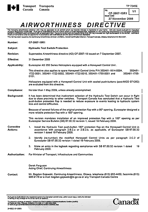
Source: Transport Canada, Airworthiness Directive CF-2007-19R1, issued 27 November 2008
Appendix B – Diagram of the hydraulic system
Activation of the HYD TEST switch opens the manifold solenoid valve and depressurizes the hydraulic system.
Activation of the HYD CUT OFF switch opens the actuator solenoid valves of each servoactuator accumulators and depressurizes the accumulators for flight without hydraulic pressure assistance.
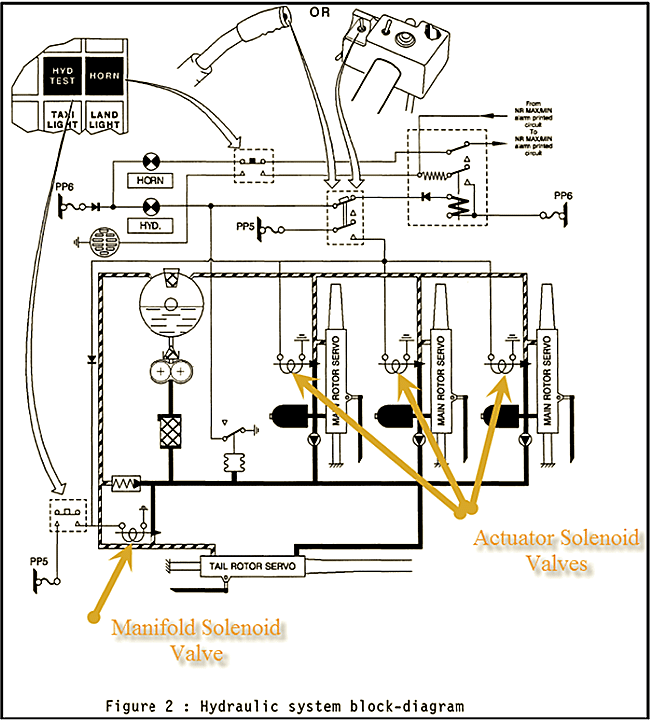
Source: Eurocopter, with TSB annotations
Appendix C – Rotorcraft flight manual Supplement No. 7
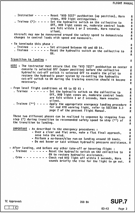
Source: Eurocopter, Flight Manual AS 350 BA Supplement, SUP 7.
Appendix D – Excerpt from Sept-Îles Airport emergency response plan
![Excerpt from Sept-Îles Airport emergency response plan [in French only]](/sites/default/files/eng/rapports-reports/aviation/2013/a13q0021/images/a13q0021-app-d.png)
Source: Sept-Îles Airport, Plan des mesures d’urgence de l’exploitant, revision 0, June 2000, p. 2-9 [in French only]