Loss of control and collision with terrain
Cessna 180G, N4695U
Trout Lake, Ontario
The Transportation Safety Board of Canada (TSB) investigated this occurrence for the purpose of advancing transportation safety. It is not the function of the Board to assign fault or determine civil or criminal liability. This report is not created for use in the context of legal, disciplinary or other proceedings. See Ownership and use of content. Masculine pronouns and position titles may be used to signify all genders to comply with the Canadian Transportation Accident Investigation and Safety Board Act (S.C. 1989, c. 3).
Summary
The privately-operated, float-equipped Cessna 180G (registration N4695U, serial number 18051395) departed Trout Lake, Ontario, with a pilot and 2 passengers on board. Shortly after take-off, the aircraft entered an uncommanded roll into a steep bank and began to descend, then struck rising terrain at approximately 0840 Central Daylight Time. The aircraft sustained substantial damage. There was no post-crash fire, and the emergency locator transmitter did not activate. The pilot and 1 passenger were seriously injured. The second passenger, who sustained minor injuries, was able to exit the aircraft and direct local residents, arriving by boat, to the crash site. The pilot and the rear-seat passenger were extricated from the wreckage and provided with first aid until emergency response personnel arrived at the occurrence site approximately 45 minutes later.
Factual information
History of the flight
The flight originated from a dock at a private cabin on Trout Lake, about 16 nautical miles (nm) west of the Kenora Airport (CYQK), Ontario. The planned destination was a lake approximately 45 nm to the northwest for a day of fishing. The pilot performed a pre-flight check and fueled the aircraft with 100 low-lead aviation fuel, which was stored on the property, to approximately 15 gallons per side. Approximately 35 pounds of cargo, consisting of fuel for a boat, fishing gear and food, was loaded into the aircraft. One passenger occupied the right front seat, and the other passenger was seated on the left side of the mid-bench seat in the cabin. Although seatbelts were available for the bench seat, the rear passenger did not use them. The pilot and front passenger used the available lap belts. The aircraft was not equipped with shoulder harnesses.
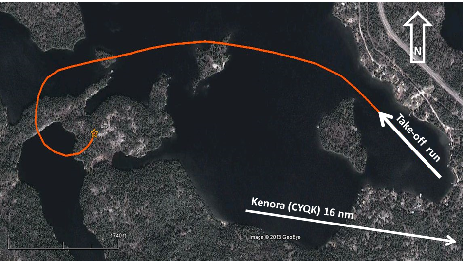
After start-up, the pilot taxied the aircraft downwind, performed a run-up, and took off approximately 6 minutes later. The aircraft performed normally during the take-off and attained a positive rate of climb. Shortly after take-off, the flaps were retracted. The airspeed was approximately 90 to 100 miles per hour (mph) during the climb. The pilot initiated a left turn to the west, to remain over water. The pilot levelled the aircraft on a westerly heading, and the aircraft climbed to about 400 feet above ground level (agl). There was an unfamiliar noise, and the aircraft began an uncommanded roll into a steep left bank. The flight controls became ineffective, and control was lost. The stall warning horn activated several times as the aircraft began to descend. The pilot altered the engine power settings several times while attempting to regain control. The aircraft yawed and rolled left, resulting in an approximately 240° change in heading (Figure 1). The aircraft collided with tree-covered, rising terrain between 2 lakes, on a heading of roughly 025° magnetic. The aircraft came to rest on its left side in front of a 10-foot-high granite wall.
Weather
At 0631,Footnote 1 NAV CANADA issued a graphical area forecast, GFACN33, valid at 0700 for Ontario and Quebec. The northwestern region of Ontario was forecast to be under the influence of a low-pressure system centred between Pickle Lake, Ontario, and Big Trout Lake, Ontario. A cold front extended southwestward from the centre of the low pressure system into northern Minnesota. The Kenora region was behind the cold front, and was forecast to have local ceilings at 1000 feet agl, and broken cloud based at 3000 feet above sea level (asl) and topped at 7000 feet asl. The wind in the Kenora region was forecast to be from the northwest at 15 knots with gusts to 25 knots. Moderate turbulence with low-level wind shear was forecast from the surface to 3000 feet agl.
The 0900 aviation routine weather report for CYQK was as follows: wind 270° true at 9 knots, visibility 15 statute miles with a few clouds based at 1800 feet agl, temperature 23°C, dew point 18°C, and altimeter setting 29.73 inches of mercury. The wind at the occurrence site was reported to be from the northwest at approximately 10 to 15 mph.
Pilot
The pilot held a United States (US) private pilot licence with a current third-class medical certificate, was rated for single-engine land and sea and for multi-engine land, and possessed a valid instrument rating. Since starting flying in 1969, the pilot had accumulated approximately 5600 hours of flying time, 2800 hours of which were on the accident aircraft. The pilot was certified and qualified for the flight in accordance with existing regulations. The pilot was familiar with the area.
Wreckage examination
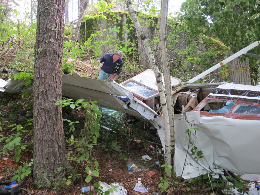
The aircraft wreckage was situated on tree-covered rocky terrain approximately 80 feet above lake level (Photo 1). The aircraft struck the ground at a descent angle of roughly 12° in a left bank. The fuselage was on its left side, with the right wing lying inverted ahead of the aircraft, but still attached at the front spar. The left wing was in 2 pieces. The inboard section was about 40 feet behind the fuselage. The outboard portion was 100 feet down the wreckage trail, in the top of a tree 20 feet above the level of the crash site.
The right wing still contained fuel, and the severed fuel lines had been plugged by local residents during the rescue. The left-wing fuel tank had burst on impact with the trees. Fuel system continuity was verified from the right-hand wing root to the firewall fuel filter, and fuel was present in the lines. The emergency locator transmitter (ELT) was attached to a removable floor panel under the pilot's seat. The ELT had remained in place, and the antenna was still connected. The switch on the ELT was in the ARM position; however, the ELT had not activated.
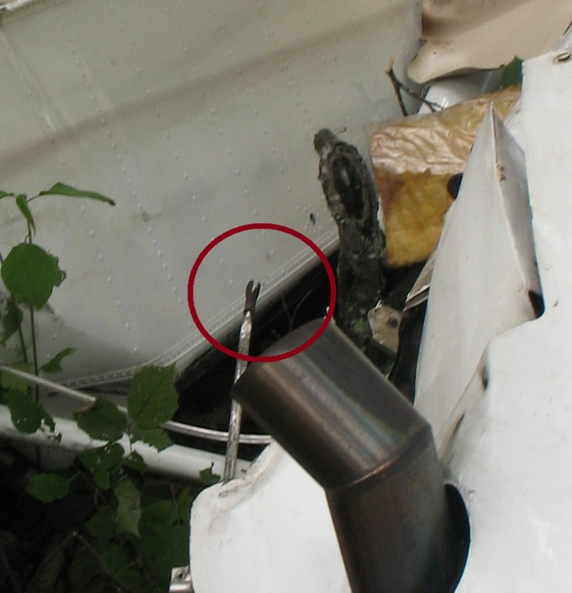
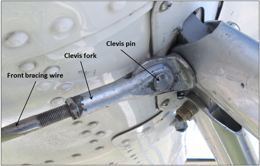
The bows of both floats were heavily damaged by impact with large trees. The front bracing wire that ran between the right float and the left fuselage attachment was lying loose in the wreckage. A clevis pin was missing from the clevis fork on the upper end of the bracing wire (Photo 2). The clevis pin in the opposite end was still in place in the clevis fork, and had been torn out of the wire-pull fitting at the front fitting of the right float. The 2 front seats were still latched on their respective seat tracks, and the seat-track safety clips were in place. The battery and master contactor had been wrenched from their mounting points, and the associated electrical cables were no longer connected. Continuity of the rudder, elevator, and stabilizer trim controls was established from the cockpit to the empennage. The flap and aileron cables had all failed close to the wing attachment points. Continuity of the flap and aileron cables was established from the cockpit to the failure points, and hence out to the wings. The flap selector was latched in the up position. The engine exhibited no sign of rotation at impact with the ground; however, at least 1 tree had been scarred with multiple slashes resembling propeller strikes.
Aircraft information
The aircraft was manufactured in 1964, and had accumulated approximately 4150 hours of tachometer time. The pilot purchased the aircraft in 1974, and operated it on wheels, skis, and floats. The aircraft was fitted with model 180-185 floats, manufactured by Aqua Floats. Records indicate that the aircraft had remained on floats from May 1987 until late 2005. The floats were removed at that time, and the aircraft was disassembled to facilitate transport to a facility for painting. The aircraft was reassembled and placed back on floats in May 2006. The aircraft remained on floats year-round after being painted. The technical records did not indicate that the floats had ever been disassembled for inspection, nor was such disassembly required. The float bracing wires were last adjusted in May 2010. The technical records indicated that the aircraft had been inspected on an annual basis and was last inspected in May 2012. Except for some discrepancies in the weight-and-balance report, the records indicated that the aircraft was equipped and maintained in accordance with existing US Federal Aviation Regulations (FARs) and approved procedures.
Weight and balance
The Aqua floats installed on the aircraft used the same loaded-aircraft moment chart, located in the Cessna C-180 Floatplane Owner's Manual Supplement, as the Model 249-2870A floats. The gross take-off weight when operated on Aqua floats was 2820 pounds. A completed weight-and-balance flight-planning form for the accident flight could not be located.
The aircraft had been modified several times over the years, and the empty weight and arm had been updated each time. At some point, the radios and autopilot (a weight of approximately 30 pounds) were removed from the aircraft, but this change was not reflected in the aircraft's revised empty weight and balance. Investigators prepared a weight-and-balance flight-planning form using estimated weights for the accident flight. Based on these calculations, the investigation determined that the occurrence aircraft was between 12 pounds under and 45 pounds above its maximum gross take-off weight. The centre of gravity was close to the aft limit.
Aircraft performance
Information obtained from the manufacturer indicated that, at the calculated gross weight and observed atmospheric conditions, an ideal aircraft should have been capable of climbing at approximately 900 feet per minute. This figure will be affected (i.e., reduced) by a number of factors, such as imprecise flight control rigging and float rigging, modifications, previous repairs, and engine performance. As a result, the actual rate of climb attainable by the accident aircraft may have been somewhat less than this figure. A sudden significant misalignment of the floats would increase the parasite drag of the floats, and increase the aircraft's induced drag as the flight controls are used to attempt to maintain directional control. The Cessna C-180 Floatplane Owner's Manual Supplement indicates that the flaps-up stall speeds should range from 64 mph with the wings level to 91 mph at a 60° angle of bank.
Engine
The Continental O-470-R(13B) engine, serial number 226858-R, was examined in detail at the Transportation Safety Board (TSB) regional wreckage examination facility in Winnipeg, Manitoba. No pre-impact defects were found that would have prevented normal operation. Impact damage precluded running the engine.
Flight controls
The complete aileron and flap control system was recovered for examination. The fractured cable ends were sent to the TSB Laboratory for fracture analysis. There were no indications of fatigue, corrosion, or long-term abrasion. It was concluded that all of these cables fractured due to overstress during the occurrence. The aileron pulley at the right-hand wing root had been rubbing against the cable guard, causing fractures in the pulley rim; however, there were no indications that the cable had slipped off of the pulley.
Floats
The Aqua float design does not use horizontal boxing wires between the spreader bars. Forward and aft pairs of bracing wires cross diagonally from side to side to take up flight loads and keep the floats in alignment (Photo 3).
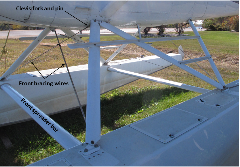
The streamlined bracing wires are formed with left-hand and right-hand threads that allow adjustment by loosening jam nuts and rotating the wire, in half-turn increments, to maintain a streamlined alignment. The bracing wires terminate at a clevis fork connected to their respective fittings by a clevis pin secured with a washer and a cotter key (Photo 4).
The orientation of the clevis pins and positioning of washers was not consistent at the various locations on the float installation. In some locations, such as the lower-aft left bracing wire attachment, the clevis pin was installed with the head down. The clevis pin on the right landing-gear attachment was installed with the head up and aft. It is common industry practice to install the clevis pin in this location with the head down and forward; however, the cotter key is hard to see in this orientation. The orientation of the missing clevis pin could not be determined. All of the bracing wires except one remained attached to their respective fittings. The bracing wire that had been connected between the right-front float fitting and the left landing-gear adapter was found lying loose in the wreckage. The lower clevis fork still retained the clevis pin, washers, and cotter key, and had been torn from the right-front float fitting wire-pull.
The wire-pull was sent to the TSB Laboratory for examination. It was determined that the wire-pull had failed in a single overload event. The clevis pin was not present in the upper clevis fork, and the wire was bent in several places. The fuselage skin and a fairing forward of the left landing-gear adapter had been damaged and cut. The damage was consistent with an object becoming pinched against the fuselage between the float strut and the landing-gear adapter during the crash. There was a small smear of white paint on the clevis fork. The clevis fork was sent to the TSB Laboratory for examination. The paint on the clevis contained a titanium oxide white colour pigment that was similar to paint samples from the floats and the aircraft itself.
Examination of the floats revealed that there was looseness between several struts and their associated deck fittings. The deck fittings and strut ends were sent to the TSB Laboratory for examination. Fretting damage and polished areas were found at the strut-attachment points of the right-front deck fitting and the left-rear deck fitting. These findings indicated that there may have been more relative movement at these locations than others. The damage to the aircraft and the floats precluded an assessment of the angular degree of misalignment that could be created between the aircraft and the floats.
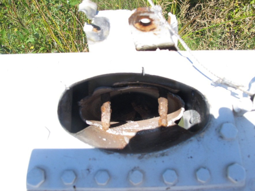
The spreader bars were found to be severely corroded within the float-socket attachment point. The corrosion had developed around wood filler plugsFootnote 2 in the spreader bars, and was concentrated around the holes for the steel through-bolts. The through-bolts were severely corroded and were impossible to remove. Bolts in the right-rear spreader bar had corroded to the point that the bolt diameters were reduced by approximately 50% (Photo 5). The front spreader bar was broken and pulled out of the left float socket. The rear spreader bar was broken at the right float, but was still captive within the socket.
The spreader bars were sent to the TSB Laboratory for examination of the fracture surfaces. Although internal corrosion of the forward and rear spreader bars and the through-bolts was deemed extensive, the corrosion was not a factor in the initiation of the fractures.
Float maintenance
The manufacturer of the floats installed on the aircraft does not publish a maintenance manual or maintenance instructions. FARs Part 91, Subpart E, governs the maintenance of US-registered civil aircraft operating within or outside of the US.Footnote 3 The owner or operator of an aircraft is responsible for ensuring that the aircraft is inspected annually in accordance with Part 43.Footnote 4 In the absence of a manufacturer's maintenance manual or instructions, Federal Aviation Administration (FAA) Advisory Circular (AC) 43.13-1B is to be used. This AC contains methods, techniques, and practices acceptable to the Administrator for the inspection and repair of civil aircraft. Chapter 9, Section 1, of AC 43.13-1B describes the inspection and maintenance of landing gear, and considers floats to be fixed gear.Footnote 5 The annual inspection requirements for fixed gear include examination for wear, deterioration, corrosion, and alignment.Footnote 6 Disassembly of the floats is not specifically required for inspection. There is also a requirement to relieve the aircraft weight from the landing gear and check for abnormal play. Inspection and repair of floats for damage and corrosion is also discussed.Footnote 7
Transportation Safety Board Laboratory reports
The following TSB Laboratory reports were completed:
- LP 151/2012 – Examination of cable fractures
- LP 165/2012 – Examination of float components
- LP 196/2012 – Examination of pitot tube debris
- LP 210/2012 – Examination of clevis fork
These reports are available from the TSB on request.
Analysis
The pilot was certified and experienced for the flight. Having flown from this location for many years, the pilot was familiar with the area chosen for the take-off, and had flown this particular aircraft for approximately 2800 hours. Therefore, pilot proficiency was not considered to be a factor in the occurrence.
This analysis will examine the issues related to loss of control, survival factors, float and aircraft maintenance, and the aircraft's performance
The float bracing wire was found loose in the wreckage. The clevis pin was missing from the clevis fork at the upper end of the bracing wire. It is likely that the clevis pin fell out after take-off before the loss of control. The absence of the clevis pin could not be explained, and because the clevis pin was not recovered, it was not possible to determine whether the correct parts had been installed. The possibility exists that the clevis pin failed in shear and allowed the bracing wire to become disconnected. The cotter key may have corroded or worn through; however, no other cotter keys displayed any signs of abnormal wear or corrosion. It is also possible that the cotter key may have been removed when the bracing wires were adjusted in May 2010. However, it could not be determined whether that was the case, as it is not usually necessary to remove the cotter key or clevis pin to accomplish this task.
Normally, floats of this design are rigid enough to remain in alignment due to the clamping action of the float struts against the attachment fittings on the fuselage and float deck. It would be expected that there would be some minor relative movement in the float attachment components, given the nature of the stresses applied. This would allow for some elasticity in the structure to absorb the landing forces. There should not be any looseness or free play in the components. The polishing and fretting damage observed suggests that there was some looseness and free play in some of the float fittings before the occurrence.
It is most likely that the bracing wire became disconnected shortly after take-off, when the unsecured clevis pin fell out. The looseness that existed at the float attachment points allowed the now-unbraced floats to twist out of alignment. The subsequent increase in parasitic and induced drag initiated a loss of airspeed. Although the exact airspeed trend was not observed or recorded, it progressed to the onset of an aerodynamic stall. Subsequent to the unfamiliar sound, this progression was indicated by the activation of the stall warning horn, the uncommanded left bank, and the ineffective flight controls. The stall occurred at an altitude of approximately 200 feet above the level of the tree tops on the surrounding terrain, and a successful recovery was not possible.
The crash site was accessible only by water. The coordination of effort between local residents and emergency services personnel contributed to the survival of the occupants. The front seats remained attached to the seat rails, and the use of seatbelts by the pilot and front-seat passenger likely contributed to their survival. The attitude in which the aircraft struck the ground may have prevented the rear passenger from intruding into the cockpit. Unrestrained occupants pose a risk of additional injury to themselves as well as to other passengers or crew in the event of a crash. Although the emergency locator transmitter (ELT) was armed and had remained in place with the antenna connected, it did not activate. The deceleration forces that were generated, as the aircraft and the floats broke apart during the descent through the trees, were not of sufficient magnitude to activate the ELT. The loss of electrical power due to the battery and master relay tearing free during the crash may have reduced the risk of a post-crash fire.
There was a discrepancy in the empty weight, so the aircraft was probably somewhat lighter than the weight and balance documents indicated, although still slightly above its maximum allowable gross take-off weight. With the exception of this discrepancy, the aircraft was maintained in accordance with the requirements of the existing regulations. Examination of the flight controls and engine revealed no abnormalities that could explain the loss of control.
The corrosion noted on the spreader bars was not visible externally, since it occurred within the spreader-bar mounting sockets. The extent of the corrosion damage suggests that periodic float removal, disassembly and thorough component inspection would be beneficial. If corrosion on the spreader bars is allowed to progress unchecked, it will eventually reach the point at which the affected components will be reduced in cross-section, such that they can no longer withstand the applied loads and may fail in service. Detection of the spreader bar corrosion and any associated repairs would require that the spreader bars be removed from the floats. Currently, there is no requirement to periodically disassemble floats for inspection. As a result, pilots and passengers travelling on float planes may be at increased risk due to undetected corrosion damage to float-attaching hardware.
Findings
Findings as to causes and contributing factors
- For undetermined reasons, a clevis pin that attached a front bracing wire to the left landing-gear adapter was not secured by a cotter key. As a result, shortly after take-off, the clevis pin likely fell out of the clevis fork, and the front bracing wire became disconnected.
- Looseness between the struts and the float attachment fittings that had developed due to long-term wear allowed the floats to twist out of alignment.
- The misaligned floats increased drag, causing a loss of airspeed, which led to the onset of an aerodynamic stall and subsequent loss of control at an altitude from which recovery was not possible.
Findings as to risk
- Currently, there is no requirement to periodically disassemble floats for inspection. As a result, pilots and passengers travelling on float planes may be at increased risk due to undetected corrosion damage to float-attaching hardware.
Other findings
- The loss of electrical power due to the battery and master relay tearing free during the crash may have reduced the risk of a post-crash fire.
- The emergency locator transmitter did not activate, likely because of insufficient impact forces. The crash site was discovered by local residents, who responded to reports of the crash.
- The passenger in the rear seat did not use the available seat belt.
This report concludes the Transportation Safety Board's investigation into this occurrence. Consequently, the Board authorized the release of this report on . It was officially released on .