Hydraulic Flight Control Malfunction
Vancouver Island Helicopters
Eurocopter AS 350 B2 (Helicopter) C-GNMJ
Kamarang, Guyana
The Transportation Safety Board of Canada (TSB) investigated this occurrence for the purpose of advancing transportation safety. It is not the function of the Board to assign fault or determine civil or criminal liability. This report is not created for use in the context of legal, disciplinary or other proceedings. See Ownership and use of content. Masculine pronouns and position titles may be used to signify all genders to comply with the Canadian Transportation Accident Investigation and Safety Board Act (S.C. 1989, c. 3).
Summary
At 1725 local time, the pilot of the Eurocopter AS 350 B2 helicopter (registration C-GNMJ, serial number 2829) with a 120-foot longline attached, entered a stable, out-of-ground-effect hover to begin coiling the longline onto the ground below the helicopter. As the pilot gradually descended, and at a height of about 10 feet above ground level, he experienced significant binding in the flight controls. The pilot was unable to rectify the control binding and had considerable difficulty maintaining attitude and altitude control of the helicopter. During 15 seconds of random, uncontrolled hover flight, the helicopter turned and climbed to about 20 feet above ground level, whereupon the pilot retarded the throttle lever, causing the main rotor rpm to decay rapidly. As a result, the helicopter descended quickly, struck the ground, bounced, and landed upright, causing substantial damage to the skids, the tail boom, and the main rotor head. The pilot was not injured and the impact forces were insufficient to activate the emergency locator transmitter.
1.0 Factual Information
1.1 History of the Flight
On the day of the accident, the Canadian-registered Eurocopter AS 350 B2 Astar (or Écureuil) helicopter had been engaged in various mining support activities without difficulty or anomaly in the jungle and terrain in the Kamarang area, Guyana, including vertical reference operations with a 120-foot longline attached to the belly hook beneath the helicopter.
At 1725 Guyana standard time,Footnote 1 the pilot had just ceased slinging operations for the day and brought the helicopter (with the longline still attached) into a stable, out-of-ground-effect hover, and began coiling the longline on the ground below the helicopter. As the pilot gradually descended, the rotor downwash began to blow the longline beneath the landing skids and, as a corrective action, the pilot raised the collective lever to briefly lift the longline to reposition it. He then intentionally allowed the nose to drift to the right to facilitate the positioning of the longline. However, at a height of about 10 feet above ground level (agl),Footnote 2 the pilot experienced a control restriction in the anti-torque pedals. The pilot also recognized that he now had considerable physical difficulty controlling the cyclic and collective sticks, and was close to losing attitude control of the helicopter as it gyrated in the pitch, roll, and yaw axes. He then found that the collective was almost immoveable, and the helicopter had climbed to about 20 feet agl. The pilot retarded the throttle lever quickly, causing the rotor rpm to immediately decay and the helicopter to descend and turn right. At this point, the warning horn for low main rotor rpm sounded;Footnote 3.
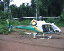
Immediately before impact, the pilot applied considerable force to raise the collective lever, which likely reduced the rate of descent. The helicopter skids struck the ground firmly-initially on the left side-while in the right turn, after which the helicopter bounced and struck the ground again, before coming to rest (see Figure 1). The helicopter remained upright and there was no main rotor blade-to-fuselage contact. Following the hard landing, the pilot secured the engine without further event; during this time, the warning horn continued to sound until silenced by the pilot.

The accident occurred during daylight and in visual meteorological conditions. The accident site was at latitude 05°53′ N and longitude 060°37′ W (about 145 nautical miles west-southwest of Georgetown, Guyana) at an elevation of 1600 feet above mean sea level.
1.2 Damage to the Aircraft
The helicopter was substantially damaged by the hard landing. During the two ground collisions, the left skid tube was fractured but remained intact, still providing support for the helicopter. The hard landing caused the tail boom to whip down, and formed a small kink in the skin, just aft of the main fuselage attachment frame (tail boom junction frame) (see Photo 1). The three main rotor bladesFootnote 4 and the two tail rotor blades were not damaged and remained attached to the helicopter. On the main rotor head, the flexible arm for the blue blade in the Starflex star assembly was fractured by the impact; the other two flexible arms were less damaged. The blade was still held captive in the main rotor head by the rigid sleeve assembly. The rotor head damage was characteristic of low main rotor speed at impact, and indicated rapid rpm decay from both the pilot retarding the throttle lever and his last application of collective pitch just before ground contact.
1.3 Pilot Information
| Licence | Commercial (Helicopter) |
|---|---|
| Medical Expiry Date | 01 July 2005 |
| Total Flying Hours | 10 200 |
| Hours Last 90 days | 206 |
| Hours on Type Last 90 Days | 206 |
| Hours off Duty Prior to Work | 12 |
Records indicate that the pilot was certified and qualified for the flight in accordance with existing Transport Canada (TC) regulations and held a valid Canadian commercial helicopter pilot licence and medical document. He had considerable flying experience on a variety of light to medium helicopters, having worked for the operator for several years on similar operations, and had accumulated significant vertical reference and remote-base experience. Records indicate that the pilot had received company flight training on the AS 350 B2 in June 2004. The training record indicated that the hydraulic malfunctions training completed by the pilot was done well. Shortly after that training, the pilot successfully completed his most recent pilot proficiency check (PPC) on the AS 350 B2.
1.4 Aircraft Information
| Manufacturer | Aérospatiale |
|---|---|
| Type and Model | AS 350 B2 |
| Year of Manufacture | 1994 as BA / Modified to B2 in 2003 |
| Serial Number | 2829 |
| Certificate of Airworthiness | Issued 16 December 2003 (H-83) |
| Total Airframe Time | 6339.8 hours |
| Engine Type (number of) | Turbomeca Arriel 1D1 (1) |
| Rotor Type | Starflex - 3 blades, composite |
| Maximum Allowable Take-off Weight | 4961 lb (2250 kg) |
| Recommended Fuel Type(s) | JP4, JP5, JP8, Jet A, Jet A1, Jet B |
| Fuel Type Used | Jet A1 |
1.4.1 Original Certification of the AS 350 Series
The basis of certification for the AS 350 series is United States Federal Aviation Regulations (FARs) Part 27 (FAR 27), Normal Category, effective 01 February 1965, including amendments 27-1 through 27-10.
The AS 350 series was introduced in 1974 by the Société Nationale Industrielle Aérospatiale (SNIA) of Marignane, France, which later was renamed Eurocopter France (ECF). The model first appeared in two forms - the AS 350 C for North American operations, and the AS 350 B for the European and other markets. The principle difference between the models was that the Avco Lycoming LTS 101 engine replaced the Turbomeca Arriel power plant installed in the AS 350 B model. In due course, several other AS 350 model variants were developed as a result of market demand and technological improvement.
Because France is the country of design, the French civil aviation authority-the Direction Générale de l'Aviation Civile (DGAC) - issued the original product type certificate (H9EU) for the AS 350 B in October 1977. In December 1977, the United States Federal Aviation Administration (FAA) certificated the AS 350 C. Production deliveries of the AS 350 model began in March 1978.
In June 1978, TC issued Canadian type certificate H-83 to the AS 350 C model as the first of the AS 350 series certificated in Canada. In February 1980, the AS 350 B was added to the data sheet of the type certificate, and in July 1988, TC certificated the AS 350 B1. In December 1990, following its technical review, TC certificated the AS 350 B2. The TC certification files for this model contained no record of specific concerns regarding the hydraulic flight control system. In August 1997, the DGAC withdrew the certification of the original AS 350 C, and as a result, TC withdrew the Canadian type certificate at the same time; accordingly, the AS 350 C is no longer certificated in Canada. The following table summarises the Canadian certification history of the AS 350.
| Date | Model | Transport Canada Action |
|---|---|---|
| June 1978 | AS 350 C | None |
| March 1979 | AS 350 D/D1 | None |
| February 1980 | AS 350 B | None |
| July 1988 | AS 350 B1 | Validated |
| December 1990 | AS 350 B2 | Reviewed |
| March 1998 | AS 350 B3 | Level 1 Review |
1.4.2 Conversion History
The accident helicopter was originally manufactured as an AS 350 BA in 1994 by Aérospatiale. In December 2003, the helicopter was converted by Eurocopter Canada to the AS 350 B2 model. Since the conversion, it has flown about 845 hours. By design, the pilot-in-command flies this particular model helicopter only from the right-hand seat.
1.4.3 Weight and Balance
Post-accident calculations reveal that, at the time of the accident, the helicopter weighed about 3450 pounds and the longitudinal centre of gravity (CG) was about 132.44 inches from the datum, with the zero-fuel weight CG about 131.87 inches. The weight and CG values were well within the limits prescribed by the TC-approved rotorcraft flight manual (RFM) and did not contribute negatively to the circumstances of this accident.
1.4.4 Maintenance
Records indicate that the helicopter was certified, equipped, and maintained in accordance with existing regulations and approved procedures.
1.4.5 Engine Information
The engine was a Turbomeca Arriel 1D1 (serial number 9911) and was not damaged. Engine logs indicate that the engine was maintained and serviced in accordance with existing Canadian regulations and approved procedures. Engine performance and mechanical malfunction of the engine was considered not to have been a factor in the accident.
1.4.6 Hydraulic Flight Control System

1.4.6.1 General Description
In flight, helicopter flight control loads principally resulting from aerodynamic forces are normally considerable and are difficult for the pilot to gauge. The flight controls in the AS 350 B2 are assisted by a single hydraulic system that reduces pilot workload during flight by absorbing these flight control loads, thereby allowing the pilot to fly the helicopter with precision and reduced effort. In the event of a loss of hydraulic pressure, the flight control loads revert to the unpowered condition. The AS 350 B2 is also equipped with a yaw load compensator that offloads much of the aerodynamic feedback force generated by the tail rotor.
1.4.6.2 Hydraulic System Components
The AS 350 B2 hydraulic system comprises the following components (see Figure 2):
- separate hydraulic reservoir;
- single hydraulic pump;
- regulator unit comprising
- pressure regulating valve
- pressure switch
- filter
- solenoid electro-valve;
- distribution system;
- flexible pressure and return hoses;
- single-cylinder main rotor servos (3), each incorporating
- accumulator
- non-return valve
- solenoid electro-valve;
- single-cylinder tail rotor servo incorporating
- accumulator
- non-return valve
- pressure relief valve
- solenoid electro-valve
- tail rotor load compensator (TRLC);
- hydraulic system warnings and controls in the cockpit
- red hydraulic warning light (HYD)
- aural warning horn (klaxon)
- hydraulic cut-off (HYD CUT OFF) switch on collective
- hydraulic accumulator test (HYD TEST) switch on centre console.
1.4.6.3 Hydraulic Servo Actuator Operation
In total, there are four hydraulic servo actuator units;Footnote 5 three main rotor servos - one longitudinal and two lateral - providing fore and aft and roll cyclic control, as well as collective control; and one tail rotor servo providing yaw control. Each of the four servos incorporates a hydraulic actuator and a hydraulic distributor. Apart from airframe mounting differences, the four servo actuators on the control linkages are identical.
Each of the three main rotor servos has a hydraulic pressure accumulator, a non-return valve, and a solenoid valve. The function of each accumulator is to provide its actuator with a small reserve of pressurized hydraulic fluid, so that in the event of loss of system hydraulic pressure, the pilot has a brief opportunity to reconfigure the helicopter to a flight regime of 40 to 60 knots, where the control feedback forces without hydraulic assistance are acceptable. The solenoid valve (also called an electro-valve) is an electrically actuated device that relieves the high-pressure hydraulic fluid at each servo and the regulator unit, thus unpowering the main rotor servos simultaneously.
The yaw load compensator is mounted in parallel with the tail rotor actuator. The tail rotor servo has a hydraulic pressure accumulator (integrated with the yaw load compensator), a non-return valve, a solenoid valve, and a check valve.
1.4.6.4 Hydraulic System Pump Operation
The hydraulic system supplies constant hydraulic power to the four servo actuators and is rated at 40 bar. A gear pump is driven at constant speed by a flexible drive belt from the engine power drive shaft to the main gearbox, with a constant outflow of six litres per minute. By design, the pump outflow exceeds the demand of the servo actuators in all normal flight conditions, and the excess flow is bypassed into the hydraulic reservoir by a regulator valve that opens when the pressure exceeds 40 bar.
The pressure regulator incorporates a pressure switch and a hydraulic test solenoid valve. The pressure switch activates when the hydraulic system pressure drops below 30 bar, illuminating the red hydraulic warning light (HYD) on the warning-caution advisory panel, and producing a steady audible alarm from the klaxon horn. When the system pressure rises above 30 bar, the light extinguishes and the horn is silenced. The same horn also provides aural warning of low or high main rotor speed, that is, when the rotor is between 250 and 360 rpm (continuous sound) and above 410 rpm (intermittent sound).
1.4.6.5 Hydraulic System Control and Monitoring
The hydraulic system is controlled by the pilot using two switches: the hydraulic cut-off (HYD CUT OFF) switch mounted on the collective lever; and the HYD TEST switch mounted in the centre console switch panel. The HYD CUT OFF switch is a guarded toggle switch with two positions - ON or OFF - and is mounted on the pilot's collective lever. The switch is normally set to the ON (forward) position (see Photo 2), allowing the servos to be powered when the hydraulic system is functioning correctly.
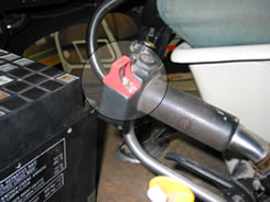
When the pilot selects the switch to the OFF (aft) position, the hydraulic system becomes depressurized, the accumulators on the three main rotor servos become depressurized simultaneously (as well as the regulator unit), but the tail rotor compensator retains its assist function (Eurocopter complementary flight manual [CFM] RR 7D, Section 7.7). In some flight regimes, because unexpected operation of this switch could lead to loss of control by the pilot, the switch is protected from unintentional movement by the plastic guard seen in Photo 2. Selecting the switch to OFF also inhibits the low hydraulic pressure warning function of the klaxon, but not the rotor rpm warning function. The accident pilot did not operate this switch in the lead-up to the loss of control; physical proof also shows that the switch was in the normal in-flight position during the event.
Opening the three main rotor solenoid valves and the regulator unit solenoid valve simultaneously with the HYD CUT OFF switch will immediately reconfigure the aircraft from the (normal) boosted flight control mode to full manual flight control mode. The flight control forces in the full manual flight control mode are consistent and reproducible, and should be familiar to the pilot through initial and recurrent hydraulics-off training. If the HYD CUT OFF switch is not used in this situation in accordance with the approved procedure, the servos will unpower asymmetrically as the accumulators bleed off, resulting in inconsistent and possibly unmanageable forces at the flight controls, which in turn may lead to loss of controlled flight. The RFM for the AS 350 B2 asserts that the forces are not unmanageable, provided the helicopter is operated in accordance with the approved contingency procedures. This also presumes that the flight control system functions as it was designed.
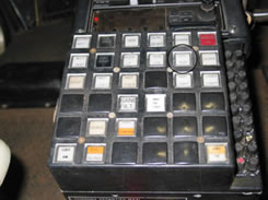
The HYD TEST switch is an illuminated, pushbutton, latched switch,Footnote 6 with two positions: TEST or OFF. In the accident helicopter, the switch is mounted in the centre console switch panel seen in Photo 3. Operating the switch verifies the correct function of the accumulators for both the main rotor and tail rotor servos, and is normally set to the OFF (up or relaxed) position. Pushing the switch down to TEST causes the solenoid valve on the regulator unit to open, thereby depressurizing the hydraulic system, and simultaneously opens the tail rotor servo solenoid valve, thereby depressurizing the tail rotor yaw load compensator. The drop in hydraulic system pressure illuminates the HYD light and the klaxon sounds. The accumulators are tested during each pre-flight check by the pilot selecting the HYD TEST switch to TEST and moving the cyclic stick to verify that the accumulators are providing assistance.
In May 2003, during the pre-flight check of an AS 350 B2 in Alberta, Canada, following the hydraulic system check to ensure that accumulator hydraulic pressure had been depleted, the cyclic control stick moved uncommanded to an extreme left position. Considerable force was required to re-centre the cyclic, and the uncommanded movement was repeatable. It was determined that this uncommanded movement is a characteristic of the SAMM servo actuator, and can be expected on the AS 350.
The RFM cautions pilots to avoid operating the HYD TEST switch in flight, since setting the switch to TEST depressurizes the accumulator in the tail rotor yaw load compensator, resulting in high tail rotor feedback forces being transmitted to the yaw pedals. However, should a tail rotor control failure occur in flight, the RFM prescribes that the pilot set the pushbutton to TEST, wait five seconds, then set it to the OFF position. This practice cuts off hydraulic power to the yaw servo and depressurizes the load-compensating servo accumulator, thus allowing the tail rotor to move to a low blade pitch setting.Footnote 7
Furthermore, the HYD TEST switch is also employed in the dual-pilot training environment as it closely simulates the symptoms of an in-flight hydraulic failure, thereby providing the pilot flying with the opportunity to practice the required contingency drills. Inadvertent operation of this HYD TEST switch is possible, and several accidents have occurred as a result (Appendix A; Air Accidents Investigation Branch [AAIB] accident report EW/C2001/1/2; Eurocopter Telex 00000188 dated 16 July 2004).
1.4.6.6 Hydraulic System Malfunction
The AS 350 B2 can be controlled without hydraulic servo actuators but it requires the pilot to exert considerable muscular effort, and in some cases of extended flight, may exceed the physical strength or endurance of an individual pilot.Footnote 8 In Canada, by TC regulation, all AS 350 pilots receive flight instruction in hydraulic failures in accordance with flight manual supplement number 7 for Canadian-registered helicopters (FMS-7) in the approved RFM. Canadian pilots are therefore familiar with the forces required to move the flight controls following a hydraulic system failure (see also Section 1.12.1.3).
In the event of a hydraulic system failure, the main servo non-return valves are closed by accumulator pressure. The pilot selects the HYD CUT OFF switch on the collective lever to the OFF position, activating the three main servo solenoid valves, and opening the servo pressure inlet to the return line, allowing simultaneous depressurization of the accumulators. This procedure is designed to dump the hydraulic system pressure to zero, and also to ensure that the accumulator hydraulic pressures are rapidly depleted to zero symmetrically. Both these functions are required for safe operation.
Dumping system hydraulic pressure to zero is required to enable the pilot to unpower the flight controls in the event of system failure or improper response. Depressurizing the accumulators symmetrically and rapidly is designed to provide consistent behaviour of the flight controls when transitioning from powered to unpowered flight controls.
The tail rotor servo non-return valve is also closed by accumulator pressure and the accumulator provides reserve pressure. Unlike the main rotor servos, the tail rotor servo system is designed to provide an almost unlimited supply of reserve pressure. If the pressure within the tail rotor servo system exceeds 55 bar, the check valve opens the pressure line to return and allows a partial hydraulic flow as the servo piston returns to the extend position. This prevents hydraulic lock and causes the stored pressure to be reduced.
1.4.6.7 Hydraulic System Certification
During original certification, the helicopter was shown to have adequate handling qualities when in the reversionary manual control mode, albeit with significantly higher control forces. However, at both high and low/hover airspeeds, the loads were considered excessive, and a safety unit (comprising the accumulator, non-return valve, and solenoid valve) was installed on each hydraulic servo. The accumulator charge generally allows the pilot sufficient time to reduce the airspeed to a value at which the manual control forces are more manageable (that is, a safety speed in the range of 40 to 60 knots), and to choose a landing area suitable for a running landing. As well, the accumulators give a pilot the choice of landing from an in-ground-effect hover, or to accelerate to the safety speed from an out-of-ground-effect hover.
Earlier design of the hydraulic system had caused unequal depletion of the hydraulic accumulators after the pilot set the HYD CUT OFF switch to OFF. As a result of an investigation involving an AS 350 B2 in 1999, the hydraulic control system was modified to ensure that the three main rotor servo actuators all dumped pressure coincidentally when the HYD CUT OFF switch was activated. This modification involved a wiring change that caused the regulator to also open, and was the subject of Eurocopter Alert Service Bulletin (ASB) 29.00.07, later mandated by France's DGAC as French Airworthiness Directive (AD) F-2004-089 and by TC as Canadian AD CF 2004-15.
1.4.6.8 Hydraulic System Failure Procedures in the Rotorcraft Flight Manual
The following prescribes the appropriate procedures for hydraulic system failures as stated in the TC-approved RFM for the AS 350 B2 (dated 2003), Section 3.2, System Failures, Subsection 4, Hydraulic System Failures.
4.1 Yaw Servo-control Slide-valve Seizure
- In hover: If no movement about the yaw axis, land normally; if rotation about the yaw axis, cut off hydraulic pressure by actuating the switch situated on the collective pitch control lever.
- In cruising flight: Reduce speed, entering into a side-slip if necessary, then cut off hydraulic pressure by actuating the switch situated on the collective pitch control lever.
4.2 Main Servo-control Slide-valve Seizure
- Actuate the switch, situated on the collective pitch control lever, to cut off hydraulic pressure.
Load feedback will be felt immediately; load feedback may be heavy if the helicopter is flying at high speed:- collective pitch: 20 kg pitch increase load
- cyclic: 7 to 4 kg left-hand cyclic load
- cyclic: 2 to 4 kg forward cyclic load
- yaw pedals: practically no load in cruising flight.
- Reduce speed to 60 knots (110 km/hr) and proceed as in the case of illumination of the HYD light.
In the event a red HYD light illuminates-signifying a loss of hydraulic pressure or pressure less than 30 bar-the pilot is required to complete the following prescribed actions as stated in Section 3.3, Warning-Caution-Advisory Panel and Aural Warning, Subsection 2.1, Red Lights (TC modification RR 3A):
Keep aircraft to a more or less level attitude. Avoid abrupt maneuvers.
CAUTION: Do not depress "HYD TEST" pushbutton as this will depressurize the yaw load compensator, resulting in heavy pedals control loads.
Do not attempt to carry out hover flight or any low speed maneuver. The intensity and direction of the control feedback forces will change rapidly. This will result in excessive pilot workload, poor aircraft control, and possible loss of control.
NOTE 1: Pressure in accumulators allows enough time to secure the flight and to establish the safety speed.
NOTE 2: Do not silence the horn by using the HORN switch. The HORN will be silenced when the pilot selects the hydraulic cut-off switch to OFF.
- In hover IGE:
- Land normally
- Collective....LOCK.
- Shutdown procedure....APPLY.
- In flight: Smoothly.
- Cyclic/collective....Set IAS within 40 to 60 kt (hydraulic failure safety speed)
- Collective HYD switch....OFF
- Pilot has to exert forces
- On collective to increase or decrease power, around no force feedback point.
- On forward and left cyclic.
LAND AS SOON AS POSSIBLE
Note: Speed may be increased as necessary but controls loads will increase with speed.
- Approach and landing:
- Over a clear and flat area, make a flat final approach, nose into wind.
- Perform a no-hover/slow run-on landing around 10 knots.
- Do not hover or taxi without hydraulic pressure assistance.
- After landing:
- Collective....LOCK.
- Shutdown procedure....APPLY.
1.4.7 Main Rotor Control
1.4.7.1 Principles of Rotor Control
The main rotor flight controls provide the mechanical link to transfer pilot input to the main rotor disc to control helicopter attitude, speed, and altitude, by constantly modifying the pitch angles of the blades as they rotate in plane. There are two pilot controls for the main rotor-the collective and cyclic sticks - directly linked to the three main rotor servos attached to the swashplate assembly on the main transmission (see Figure 3).

In summary, the collective control stick changes the blade pitch angle on all three blades equally and simultaneously, essentially providing vertical control (altitude), whereas the cyclic control stick changes the blade pitch angle on the blades independently and variably as they rotate around in the rotor disc, providing disc attitude control (speed and angle of bank). The same basic control principle applies also to the tail rotor, but in a less complex manner.
1.4.7.2 Collective Pitch Action
The collective pitch stick simultaneously moves the three servos the same amount, in the same direction, and at the same rate. In Figure 4 and Figure 5, for example, if the pilot raised the collective, the servos at A, B, and C would extend (rise) together. That increment would cause the swashplate(s) to rise and impart an identical and simultaneous increase of blade pitch angle on each main rotor blade.

1.4.7.3 Cyclic Pitch Action
The cyclic stick moves the three servos at varying amounts, and at the same rate, depending on the direction the cyclic has moved. Since each servo moves independently, by design, the swashplate swivels about two fixed axes and tilts in the direction in which the cyclic is moved (see Figure 4). For example, if the pilot moved the cyclic purely to the right, the servo at C would extend (rise), the servo at A would retract (lower) by the identical amount and the forward servo at B would not move. Those movements would cause the swashplate to tilt to the right about the roll control hinge line and impart a varying change of blade pitch angle on each main rotor blade as it rotates around the rotor plane, so that the disc tilts to the right about the roll axis.
With purely fore and aft cyclic movement, a similar action takes place, with the servo at B extending or retracting and tilting the swashplate about the pitch control hinge line seen in Figure 5, thus tilting the rotor disc about the pitch axis. In flight, the cyclic inputs are usually a combination of lateral and fore and aft movements, and the swashplate tilts about both swashplate hinge lines in an amount proportional to the cyclic stick displacement and its direction in the cockpit. The description of servo response to cyclic and collective movements is based on normally functioning servos. Were one servo to operate at a different rate than the other, particularly in the case of the lateral servos, which operate in proportional opposition, it could lead to inconsistent flight control response and could be difficult for the pilot to gauge.

1.4.8 AS 350 B2 Klaxon Warning Horn
1.4.8.1 Low Rotor Speed Aural Warning
The aural warning alerting the pilot to the loss of main rotor speed is provided by a klaxon horn, triggered by an electronic rpm sensor unit in the main rotor head. The horn is an imposing sound and warns of rapidly decaying rotor speed, usually resulting from engine power loss. To maintain control of the helicopter, the pilot is required to immediately lower the collective pitch lever to reduce blade pitch angle so as to recover and preserve rotor speed within acceptable autorotation rpm limits. As well, the pilot seeks to attain an appropriate airspeed, depending on the flight regime at the time of rpm loss, using aggressive cyclic movement. These actions stabilize the helicopter in autorotative flight and give the pilot maximum opportunity to achieve a successful engine-inoperative landing, usually at low speed. The reaction to this low rotor speed warning must be timely and rapid - in the order of two seconds - since decayed rpm is not always retrievable, and rotor rpm below the minimum for controlled flight is irrecoverable.
1.4.8.2 Low Hydraulic System Pressure Aural Warning
By Eurocopter design, the aural warning alerting the pilot to the hydraulic system pressure reducing below 30 bar is also provided by the klaxon horn, triggered by a pressure sensor switch in the hydraulic system. The horn draws attention to a failing pressure situation and, according to a TC-approved procedure, requires the pilot to smoothly reduce the airspeed to the "hydraulic failure safety speed" of 40 to 60 knots.
Conventionally, such a reduction in airspeed is accomplished by a gradual, rearward movement of the cyclic stick, and a progressive lowering of the collective lever. This action assures that the helicopter is stabilized in a flight regime that has been shown to have acceptable flight control loads, and thus be manageable for the pilot to maintain control. The reaction to this low pressure warning is not required to be imperatively fast-it is a warning that system hydraulic pressure has been lost and that the pilot has a period in the order of 30 seconds to respond. This reaction is in sharp contrast to that required for the low rotor speed warning.
1.4.8.3 Main Rotor Low Speed Warning Certification
FAR 27.33, Main Rotor Speed and Pitch Limits, was silent with respect to main rotor low speed warning. However, in March 1978, Amendment 14 to FAR 27.33 significantly improved the provisions for main rotor speed warning, and in Paragraph (e), Main Rotor Low Speed Warning for Helicopters, a new part (3) required that the warning be clearly distinguishable from all other warnings. This requirement has been the certification standard for single-engine helicopters since 1978 and embodies a valid principle of rotorcraft flight safety.
1.5 Meteorological Information
No formal weather report for the accident site exists. It was reported that the weather conditions met visual meteorological conditions (VMC) criteria and were suitable for flight in accordance with visual flight rules (VFR). A light wind existed from the east with an outside air temperature of about 25°C. Accordingly, weather is not a contributing factor in this accident. However, it should be noted that, around the time of the accident, the helicopter was generating a substantial amount of static electricity, which was seen to discharge from the hook in large electric arcs.Footnote 9
1.6 Aerodrome Information
The accident occurred while the helicopter was hovering above the intended landing area, which consisted of dry, argillaceous earth. The landing site was well prepared for landing and take-off operations and had been used by the operator as the base staging area for light maintenance and refuelling. The site is in a clear, open, flat space without significant obstruction to the take-off and landing paths. Accordingly, the landing site was not a contributing factor in the circumstances of this accident.
1.7 Flight Recorders
The helicopter was not equipped with a flight data recorder or a cockpit voice recorder, nor was either required by regulation in Canada or Guyana.
1.8 Wreckage and Impact Information
1.8.1 Mechanical Flight Control System
The complete mechanical flight control system was examined and no deficiency or anomaly was found that would have either precipitated the in-flight upset or prevented normal flight control function.
1.8.2 Servo Examination
The Dunlop hydraulic servos installed on the accident helicopter have a service life of 1800 hours before requiring overhaul.Footnote 10 The recorded time remaining before overhaul on these particular servos varied from 328 to 1115 hours.
Each servo was bench-tested by the TSB for its ability to carry specification static load; each servo surpassed the test load and met specification. Next, the test for servo creep was carried out on each servo; results show that only the forward servo was acceptable. Servo valve internal leakage was then measured, resulting in only the right lateral and the tail rotor servos passing the test. The left lateral and the forward servos both failed remarkably, and in the case of the forward servo, with gross deviation from the maximum acceptable leak rate.
The servos were then individually subjected to multiple cycles of extension and retraction for full actuator travel and the results varied widely; the left and right lateral servos demonstrated remarkable differences. Associated with each of the four servos is an electrically operated valve (electro-valve) that opens to dump hydraulic pressure in its own servo; the direct current (DC) voltage was measured during the bench tests and found to be reasonably consistent. The following table summarises the results of all the tests:
| Servo Location | Load Test | Creep Test | Leak Test | Extend (seconds) | Retract (seconds) | Electro-valve (volts DC) |
|---|---|---|---|---|---|---|
| Left lateral | Pass | Fail | Fail | 0.9 | 3.4 | 10.9 |
| Right lateral | Pass | Fail | Pass | 1.0 | 2.5 | 11.5 |
| Forward | Pass | Pass | Fail | 1.7 | 1.66 | 10.6 |
| Tail rotor | Pass | Fail | Pass | 1.6 | 1.6 | 7.8 |
Following the examination and functional testing performed by the TSB in Richmond, British Columbia, the servos and selected hydraulic components were examined by ECF in Marignane, France. Although Eurocopter did not participate in the TSB tests, their own tests revealed similar results with the same servos. In summary, the ECF test showed that the left and right lateral servos met neither the design nor the certification tolerances for extension and retraction speeds. The following table summarises the results of the tests:
| Servo Location | Serial Number | Extend Speed (mm/sec) | Retract Speed (mm/sec) | ||
|---|---|---|---|---|---|
| Design Range | Actual | Design Range | Actual | ||
| Left lateral | CW526 | 120 - 100 | 188 | 120 - 100 | 57 |
| Right lateral | LA166 | 120 - 100 | 182 | 120 - 100 | 72 |
| Forward | BJ056 | 130 -100 | 117 | 120 - 100 | 117 |
| Tail rotor | BQ387 | 120 - 100 | 115 | 120 - 100 | 94 |
1.8.3 Servo Actuator Accumulators Examination
By design, the servo accumulators are charged with nitrogen to a pressure of about 15 bar. During the TSB bench-test examination of the servos, the pressure in each of the three main rotor servo accumulators was found to be about 15 bar. The tail rotor servo accumulator pressure was not measured, but the compensator unit was inspected and tested in accordance with overhaul procedures and only one anomaly was found. By design, the pressure regulating valve should open between 49.6 and 60.7 bar, but during the bench-test, it consistently opened at 62 bar. Technical assessment by the servo overhaul facility in British Columbia and Eurocopter indicated that this consistent variation from the upper limit is negligible and would not have played any part in the accident circumstances.
The main rotor accumulators were tested to determine the time to exhaust the hydraulic pressure in their respective servos. Results varied from 158 seconds for the forward servo, 80 seconds for the left lateral, and 137 seconds for the right lateral. It should be noted that the servo actuator rates are in sympathy with the accumulator depletion times. These measured times reflect bench-test conditions, whereas in-flight and hovering conditions would significantly diminish the time to exhaust the accumulator hydraulic pressure.
Nonetheless, the wide static variance is of some interest because it does indicate that the accumulators would have exhausted at different times following a loss of system hydraulic pressure, thereby potentially leading to asymmetrical flight control forces. By design, this undesirable situation is prevented by the pilot operating the hydraulic pressure cut-off switch on the collective stick, thereby dropping system pressure on each servo and accumulator at the same time, provided that the pilot operates the switch before any of the accumulators is exhausted.
The pre-flight hydraulic accumulator check prescribed in the Eurocopter RFM (RR 3a, page 5) advises that there should be two or three cyclic control movements before accumulator hydraulic pressure is lost. Furthermore, the RFM (RR 7D, page 7) advises that it takes less than 30 seconds to attain the safety speed.
1.8.4 Hydraulic Cut-off Switch Examination
The collective HYD CUT OFF switch (Honeywell part number 12TW1-3) is a double-pole, double-throw (DPDT) toggle switch, which is attached to six insulated, flexible-strand wires that pass inside the collective lever itself. By design, the wires are soldered to the switch terminals and appropriately insulated. The HYD CUT OFF switch was disassembled by the TSB, and discrepancies that indicate a pre-existing condition that may have prevented normal switch function were noted. This switch is electrically protected by the hydraulic circuit fuse, which was noted to be intact during the examination. A continuity check and a functional test of the HYD CUT OFF switch were conducted, and discrepancies were noted.
The accident switch was poorly soldered and missing the insulating material. No indication of arcing was found on the terminals, but the switch contacts inside the sealed switch case were contaminated with dirt and dust. Bench-testing of the switch found no functional anomaly at that time. The detailed examination and testing of the switch found that the wire connections were cold-soldered, which is a soldering technique flaw. However, the connections were solid and exhibited electrical continuity.
1.8.5 Hydraulic Test Switch on the Centre Pedestal
Immediately after the accident, the position of the HYD TEST switch was recorded as being in the normal OFF position. Had this switch been depressed, the klaxon horn would have sounded immediately; it did not sound until the pilot retarded the throttle and the main rotor rpm decayed.
1.8.6 Hydraulic Fluid Examination
Four hydraulic fluid samples were taken from the hydraulic system and analysed by a commercial laboratory in Surrey, British Columbia. The fluid samples were all found to conform to military specification H-5606, which is appropriate for this helicopter. Of the four fluid samples, only the one from the regulator unit was remarkably contaminated with a high level of particulate. Laboratory analysis of the contamination revealed that it comprised severe wear particles, metallo-oxide steel wear particles, rust particles, and unidentified amorphous particles.
As well, the filter from the regulator unit-the last defence before the servo actuators-was examined for contamination, and similar particulate contaminant was found. Some of the severe wear particles exceeded 50 microns in dimension, and some showed striations that indicated metal-to-metal scraping contact. Other particles were smooth and flat from surface delamination, indicating fatigue of the surface layer of metal.
Subsequent examination of all the hydraulic system components, however, did not reveal the source of the particulate contamination, and no component showed associated wear. Examination of the system suggested that the contamination was likely captured by the regulator filter and did not pass downstream into the other components. The progressive examination process did not allow thorough examination of the servo actuators for contamination before they were tested as installed on the helicopter. As a result, it could not be determined if contamination had passed into the actuator(s) and then flushed out during the functional tests nor could it be determined when the contamination occurred or how it originally entered the system.
1.8.7 Warning Horn and Electrical System
The electrical services associated with the flight controls and hydraulic systems were examined. The low hydraulic pressure warning horn was tested, and it functioned correctly and consistently; no fault was found. The warning horn mute switch was found in the normal ON position; had it been otherwise, the horn would not have sounded in flight or on the ground.
1.8.8 Electrical Fuses and Circuit Breakers
No electrical circuit fuses were found blown or circuit breakers found tripped during the accident sequence or during the examination of the airframe carried out by the TSB in Canada. Helicopter static electricity tests revealed appropriate and correct bonding devices and grounding pathways.
1.8.9 Electrical System Printed Circuit Boards
Six printed circuit boards, which controlled the hydraulic system operation and warnings, and many other electrical functions of the helicopter's electrical system were examined and tested by the TSB Engineering Laboratory. All boards were assessed as functional without defect, except for flaws in the conformal coating on both the 22-alpha board connecting the collective lever switches, and the 30-alpha board connecting the centre pedestal switches. It is unlikely that these flaws caused any malfunction.
During the examination of the centre pedestal in the helicopter, a significant amount of contamination - comprising earth and other foreign matter - was found on the 30-delta board and its edge-card connector. This board functions as an interconnect board and, among other things, provides electrical power to both the warning light and horn for the hydraulic system. As connected, the metallic edge terminals on the board were exposed to the contamination and electrical continuity would have been affected had conductive material fallen onto them. A laboratory examination of the contamination revealed that it was essentially non-conductive either wet or dry, but several flakes of conductive material were present. No indication of electrical arcing was found on the terminals, and the source of the flakes was not identified.
The environment where the helicopter was operating was bare earth and a mineral-rich soil. The location and orientation of the boards in the centre pedestal makes them vulnerable to contamination, vibration, and damage. The boards and connectors are exposed and have no prophylactic barrier to prevent the accumulation of dirt, fluids, and metal filings from the console components above. As a result, electrical interference from contamination cannot be ruled out as a contributing factor in this accident.
1.9 Medical and Pathological Information
There was no indication that physiological or psychological factors contributed adversely to this accident. The pilot was a tall and powerful man, and his size and physical strength were beneficial factors in the successful outcome of this control malfunction.
1.10 Survival Aspects
Although the helicopter sustained substantial damage, the pilot was uninjured. The impact forces were insufficient to activate the emergency locator transmitter (ELT). The helicopter remained upright at landing and kept its structural integrity. The company satellite telephone communication network was functional and provided timely notification and response.
1.11 Tests and Research
1.11.1 Australian Department of Defence Evaluation of the AS 350 BA
In 1997, following a hydraulics-out landing accident, the Royal Australian Air Force (RAAF) tasked a formal evaluation of the handling qualities of the AS 350 BA with a hydraulic system malfunction. The goal of the test program was to determine if the flight manual emergency procedures, approach and landing techniques, and operating limits for the AS 350 BA required amending due to control forces, handling qualities, or control authority during hydraulic malfunctions. The result of the assessment was that, during hydraulics-out flight at high gross weight, the substantially reduced control authority, the considerably increased control free play, and the greatly increased control forces in all control axes were unacceptable and caused a loss of control during low-speed flight.
The Department of Defence report (AR-009-993) is approved for public release and in part concludes that, with respect to hydraulics-out flight:
- the reduced control authority in the collective was unacceptable;
- the high forces in the collective control were unacceptable;
- the reduction in servo authority in cyclic control was unacceptable;
- the cyclic free play was unacceptable;
- the high forces in the longitudinal cyclic control axis were unacceptable; and
- the high forces in the lateral cyclic control axis were unacceptable.
The AS 350 B2 hydraulic system differs from that in the BA model by the addition of the tail rotor compensator unit; otherwise, the systems are identical.
1.11.2 Hydraulic Cut-off Switch Failures
Research conducted after the accident reveals several recent failures of this particular collective HYD CUT OFF switch (part number 12TW1-3). Furthermore, the failures were not confined to in-service switches, but also occurred to new switches supplied directly from helicopter manufacturer spare parts inventories. The TC Service Difficulty Report (SDR) database records instances where the switch operated intermittently or incompletely (that is, not all expected functions occurred).
TSB research of switch sales data from Eurocopter Canada for 2004 and 2005 shows that a total of 22 replacement switches (nine 12TW1-3 and thirteen MS27719-23) were issued to Canada's civilian operators of the AS 350. This total accounts for only those switches sold by Eurocopter Canada and does not include other vendors' sales or the replacements out of operators' existing spares. Since the switch is an on-condition item, it is replaced when it fails.
The TSB Engineering Laboratory examined some of these failed switches, and determined that the 12TW1-3 switch is underrated for its present application in the AS 350 B2 (TSB Engineering Laboratory report LP 23/2005).
1.12 Organizational and Management Information
1.12.1 Transport Canada
1.12.1.1 Hydraulic Failure - Flight Control Loads
As a result of a fatal accident in Mekatina, Ontario, on 21 January 2003Footnote 11 involving an AS 350 B2, TC participated in an examination of the hydraulics-off handling qualities of the helicopter type with a team of Eurocopter flight test specialists in November 2003. The goal of the study was to understand the in-flight characteristics of the helicopter with abnormally behaving servo actuators. TC's assessment of the flight control loads showed that the forces were high during the safety speed range (40 to 60 knots) and during hover flight. Section 7.7 of the RFM (RR 7D) contains Subsection 4.2, Hydraulic Pressure Loss, which states that, if the helicopter is hovered without hydraulic assistance, the control load forces change, in both direction and intensity, as the pilot attempts to maintain a steady position. In summary, TC concluded that the handling qualities of the AS 350 without hydraulic assistance were marginally acceptable, except for hover and hover-landing flight. TC found that performing landings from the hover without hydraulic assistance required excessive pilot skill and strength, and that the Eurocopter recommendation not to hover is sound. This finding was emphasized by the extremely high yaw pedal force (in excess of 70 pounds) required to maintain heading at below translational lift airspeed, with the tail rotor servo compensator discharged (HYD TEST switch in TEST position).
ECF had little hydraulics-off certification data for extreme cold-weather operations. As a result, TC identified the need to gather detailed information about extreme cold-weather flight control behaviour, as well as the operating characteristics of the hydraulic flight control system under boosted and manual operation. Accordingly, in February 2004, TC led another examination of the hydraulics-off handling qualities of this helicopter, including extremely cold-weather conditions, with a similar team of flight test specialists as before. The cold-weather aspect was part of the original flight test design review conducted in November 2003. Included in this flight test program was the assessment of a prototype wiring modification that would form the basis for the ADs issued later that year (F-2004-089 and CF 2004-15).
The conclusion of the cold-weather investigation was that the residual hydraulic pressure, following activation of the HYD CUT OFF switch in cold temperatures, could remain high enough to retain one or more actuators in boosted mode, with the other actuators in manual mode, causing inconsistent and asymmetric flight control loads that could lead to loss of control of the rotorcraft.
AD CF 2004-15 introduced a wiring change that ensured that, following activation of the HYD CUT OFF switch in all temperature regimes, the residual pressure in the hydraulic system would be below that which would allow any of the actuators to remain in boosted mode, thereby effecting immediate reversion to full manual flight control mode. As a result of this change, the flight control loads were consistent, reproducible, and familiar to the pilot, facilitated by initial and recurrent hydraulics-off training.
The findings of the November 2003 flight tests were that the flight control forces were high at speeds higher than the safety speed, acceptable in the safety speed range, and very high and unstable in both direction and intensity in hover. TC observed that, while these very high flight control loads for hydraulics-off flight were marginally acceptableFootnote 12 for legacyFootnote 13 helicopters, they now would not be acceptable on a new helicopter design.
1.12.1.2 Canadian Airworthiness Directives and Airworthiness Notice
TC issued Urgent AD CF-2003-15, dated 16 May 2003, which in summary required pilots of the AS 350 helicopter to functionally check the hydraulic accumulators before flight, required them to land as soon as possible after a hydraulic system malfunction, and prohibited non-emergency flight with the hydraulic system turned off. This original AD was superseded by AD CF-2003-15R1, dated 01 July 2003, which prescribed that the pre-flight accumulator check be carried out before every flight.
In September 2003, TC issued Airworthiness Notice (AN) D006, Edition 1, to address concerns with the flight control characteristics of the AS 350 when hydraulic system pressure is lost. Eurocopter tests showed that an uncommanded servo actuator movement is possible when one lateral accumulator is depleted and the other is charged; TC assessed that similar results would occur in flight. The AN goes on to say that this uncommanded movement is prevented in flight when the pilot follows the procedure in the TC-approved RFM, which prescribes that, following a hydraulic failure, the helicopter is slowed promptly to a specified safety speed and the HYD CUT OFF switch on the collective lever is set to OFF. When the pilot turns the switch off, any unbalanced force caused by asymmetric residual pressure in an accumulator is avoided. In the event that the HYD CUT OFF switch was not used and the accumulators were to deplete at a different rate by normal flight control movements, sustained and asymmetric hydraulic pressures may occur.
Several SDRs contained in the TC SDR database record unexplained, uncommanded servo movements. Information from Eurocopter indicated that possible flight control loads could be encountered that would exceed the strength of the pilot to continue safe flight and landing. Following the engineering review precipitated by the Mekatina accident, TC conducted extreme cold-weather trials at Inuvik, Northwest Territories. Part of the tests revealed the following information:
Manual flight control loads at these extreme temperatures were acceptable, but were marginal for longitudinal cyclic. This reinforced the requirement prescribed in the approved emergency procedures to maintain forward speed when landing the helicopter.
Higher-than-expected residual hydraulic pressure with the system in bypass. These pressures were high enough to retain one (or more) actuators in boosted mode, with the other actuators in manual mode resulting in inconsistent and asymmetric flight control loads that could possibly lead to loss of control of the rotorcraft.
The flight restrictions imposed by AD CF-2003-15, however, created a situation wherein recurrent flight training for hydraulic pressure failure was prohibited. TC recognized that the lack of training may have an adverse effect on flight safety. Consequently, AD CF-2003-15R1 was superseded by ADs CF-2003-15R2 and CF-2003-15R3. The latter AD approved in-flight deactivation of the hydraulic system to provide meaningful training for hydraulic pressure failure as in FMS-7. In November 2004, France's DGAC issued AD F-2004-174, which mandated the procedures contained in the flight manual supplements for various AS 350 series helicopters (for example, FMS-7 for the AS 350 B2). In May 2005, following TC's review and acceptance of France's AD, TC cancelled the parallel Canadian AD (CF-2003-15R3).
It was reported to TC that, after the issuance of AD CF-2003-15, an instance of flight control rate-limiting occurred in flight where the pilot was only able to move the cyclic stick at a specific maximum rate, regardless of the force the pilot applied to the cyclic. This rate restriction did not limit the available cyclic displacement, it did not introduce uncommanded control inputs, nor did it affect the controllability with the hydraulic system turned off (TC's AN D0006 refers).
1.12.1.3 Canadian Rotorcraft Flight Manual Supplement Number 7
It appears that the Canadian helicopter industry's attention to several hydraulic system anomalies in the AS 350 helicopter has promoted the focus on proper and standardised training in this area.
To further this perspective, and resulting from the above-mentioned series of ADs, the TC-approved RFM for the AS 350 B2 includes FMS-7, which prescribes the procedures for in-flight training for hydraulic pressure failure. Of greater interest is the associated caution to not ". . . carry out hover flight or any low speed manoeuvre without hydraulic pressure assistance." The caution explains that "The intensity and direction of the control feedback forces will change rapidly. This will result in excessive pilot workload, poor helicopter control, and possible loss of control." As well, FMS-7 identifies the procedural safety speed as between 40 and 60 knots.
Given the demonstrated handling characteristics of the AS 350 B2 without hydraulic system pressure, the formal training procedures contained in Canada's FMS-7 contribute to the safe operating practices for this helicopter. This is accomplished by providing proven and standardised actions to allow pilots to recognize an in-flight hydraulic anomaly, to manipulate the helicopter with the attendant flight control loads, and to practise correct in-flight drills to recover from the system failure and land without further event.
An RFM supplement normally requires compliance only when the subject equipment (or function) is installed. For example, the provisions of an FMS for a cargo hook apply only when the hook is installed on the helicopter; once the hook is removed, the FMS is no longer applicable. In the case of FMS-7 for hydraulic training, it is an operating procedures instruction that applies to all configurations, and therefore has no limitation to its implementation in the AS 350 B2. In summary, therefore, it can be said that FMS-7 requires that any hydraulic failure training be carried out in accordance with the prescribed procedures, but the FMS itself does not require that the training be performed in the first place. There is a provision in the Canadian Aviation Regulations (CARs)Footnote 14 that requires commercial operators of the AS 350 to carry out appropriate hydraulic system failure training, and as a result, the intent of FMS-7 would be achieved.
There is no such regulation for the non-commercial sector. However, because of Canada's strict pilot licensing policies regarding helicopter type ratings,Footnote 15 the same safety benefits of those training procedures in FMS-7 are generally realised in private-sector aviation in Canada, albeit not as frequently as in the commercial sector.
In Canada, therefore, all pilots with the AS 350 endorsement on their licences would have undergone such hydraulic system failure training, and would have been examined on their handling abilities before receiving that endorsement. Each commercial pilot would be trained and re-checked annually as part of the required pilot proficiency or competency check process. In the private sector, however, no such check is required and the hydraulics-off exposure would not be repeated. After their initial training and licence endorsement, some AS 350 pilots in Canada receive no further flight instruction in, or exposure to, hydraulic system failure.
The benefit of recurrent training includes refreshed awareness of the AS 350 hydraulic system malfunctions, familiarity and practice with the approved emergency procedures, exposure to the unusual manifestations of those malfunctions, and the tactile demonstration of the unusually high control forces that occur during hydraulics-off flight. Because the AS 350 handling qualities are significantly different from similar helicopters, TC identified that the lack of training in hydraulics-off operations posed a risk to flight safety (TC's AN D006).
1.12.2 Direction Générale de l'Aviation Civile
Following the series of flight tests by TC, the DGAC took the following safety action:
- issued AD F-2004-174, which prescribed amendments to the basic RFM that improved the description and procedures of the hydraulic system, and enhanced hydraulic failure training (FMS-7); in Canada, these were mandated when TC issued AD CF-2003-15R2; and
- issued AD F-2004-089 (23 June 2004) that modified the hydraulic bypass system; in Canada, this AD was superseded when TC issued Canadian AD CF-2004-15.
1.13 Other Relevant Information
1.13.1 Hydraulic Test Switch Inadvertent Activation
Although not a factor in this accident, the ergonomic function of the HYD TEST switch became a point of interest during this investigation. By design, the HYD TEST switch is positioned adjacent to other similarly shaped switches that control frequently used electrical services: the position, strobe, taxi, and landing lights, and the klaxon horn. Several instances have been recorded of inadvertent operation of the HYD TEST switch when the pilot intended to operate one of the adjacent switch functions. As a result of such an accident with an AS 350 B3, Eurocopter France issued a four-page information notice (Telex Info) in July 2004 that informed pilots of the AS 350 helicopter about the function, the proper use, and the consequences of using the HYD TEST switch. In November 2005, Eurocopter issued Service Bulletin (SB) 67.00.32, which recommended the installation of a retractable guard/cover (protection flap) over the switch in several models of the AS 350 helicopter to physically prevent unintentional operation of the HYD TEST switch. The guard was not installed on the accident helicopter because it was not available until nine months after the accident.
1.13.2 Electro-Valve Wiring Modification
Eurocopter issued ASB 29.00.07 (dated 08 April 2004) that improved the functionality of the HYD CUT OFF switch. The ASB was mandated by the DGAC in June 2004 as French AD F-2004-089, and by TC in August 2004 as Canadian AD CF 2004-15. The intent of the ASB/AD action was to ". . . eliminate the possibility of a load imbalance of the flight controls due to residual pressure in the system after cutting off the hydraulic assistance." This was achieved by modifying the existing electrical circuit to permit the simultaneous opening of the four electro-valves for the three main rotor servos and the regulator unit. TC issued the separate Canadian AD, superseding the French AD, to shorten the compliance time, ensuring that Canadian helicopters were not exposed to cold-weather operations without the modification.
Examinations of the maintenance records and the airframe of C-GNMJ show that this modification had been implemented by Eurocopter Canada during the factory conversion from the BA model to the B2 in November 2003. Although this particular modification action did not conform to the specific instructions contained in the AD since the electrical wiring was changed in a different location, the electrical effect and intended functionality was identical to the formal modification. Only one other helicopter modified by Eurocopter Canada was changed in this manner, and it is reported that the rationale for the deviation in wiring routing was better accessibility during the model change progress. The other AS 350 similarly modified has not experienced electrical or hydraulic anomaly.
1.13.3 Electro-Valve Wiring Diagram
During the investigation, the TSB identified that the original Eurocopter electrical wiring diagram (29.00.00, version 93-44) depicting the wiring paths from the collective switch to the three servo electro-valves was inconsistent with the wiring found on the helicopter. Discussions with Eurocopter revealed that a drawing error on the circuit diagram had occurred with the front and left-hand electro-valve block diagrams. Eurocopter revised the wiring diagram with version 06-03, which correctly shows the wiring to the electro-valves. Had the wiring been installed in accordance with the original Eurocopter wiring diagram, a single electrical malfunction would have occurred, blowing the hydraulic fuse. The wiring in C-GNMJ was correctly installed, and this issue was not a contributing factor in this accident.
1.13.4 Hydraulic Cut-off Switch Electrical Rating
In the AS 350 B2, the collective HYD CUT OFF switch is controlling an inductive electrical load from the four electro-valves that individually draw about 1 ampere (A) of current when operated. All four electro-valves are connected in parallel and, when operated, the total draw is about 4 A.
The 12TW1-3 switch is manufactured to the original specification sheet from Honeywell for the TW series of miniature toggle switches and may control either direct current (DC) or alternating current (AC). By design, the switch series meets military specification MIL-S-83781,Footnote 16 and the Honeywell specification sheet shows that the switch electrical rating for the 30 volts DC application is 5 A resistive, and 2 A inductive loading; in other words, the switch was designed to carry a maximum inductive electrical load of 2 A at 30 volts DC. The following electrical rating table is taken from the specification sheet for the TW series of manual switches, and the 30 volts DC reference applies to the 12TW1-3 switch installed in the AS 350:
| Volts(TW Series Switch) | Amperes | ||
|---|---|---|---|
| Resistive | Inductive | Lamp | |
| 30 volts DC | 5 | 2 | 1 |
| 115 volts AC | 5 | 2 | 1 |
Section 11, Subpart 11-53, of United States FAA Advisory Circular (AC) 43.13-1B in part identifies the electrical standard for switches. This subpart states, among other things, that a switch should be derated from its nominal current rating when controlling an inductive circuit, since the "magnetic energy stored in solenoid or relay coils that is released when the control switch is opened and may appear as an arc." The amount of derating is identified as a derating factor, and varies with nominal system voltage and the type of load. Table 11-4, Switch Derating Factors, from AC 43.13-1B for 28 volts DC nominal system voltage, is repeated below.
| Type of Load | Derating Factor |
|---|---|
| Lamp | 8 |
| Inductive (relay-solenoid) | 4 |
| Resistive (heater) | 2 |
| Motor | 3 |
According to this table, the derating factor is 4 for the switch in this particular AS 350 B2 application, and the result is that the nominal rating is four times the continuous rating. The table shows that the lamp load derating factor is double the inductive (relay-solenoid) load factor, which itself is double the resistive load factor. This electrical proportionality is similar to the Honeywell specifications for the same loads.
By applying the derating factor of 4 from AC 43.13-1B to the Honeywell specification rating of 5 A for the 12TW1-3 switch, it can be seen that the maximum inductive load is 1.25 A. As well, just by considering that the inductive load is half the resistive load, the maximum inductive load would be 2.5 A. In either calculation, the electrical load of 4 A exceeds the maximum inductive load value.
It is noteworthy that, in earlier models of the AS 350, the inductive electrical load was less than current models because there were only three hydraulic system electro-valves connected to the collective switch. Eurocopter's improvement and modification to the electrical and hydraulic systems of subsequent models added the regulator electro-valve to the collective switch, thereby increasing the inductive load by 33 per cent. It could reasonably be argued that the initial installation also exceeded the maximum inductive load value for the switch in this helicopter. Additionally, current information from Honeywell warns that the 12TW1-3 switch (military part number MS27719-23-1) cannot be used as ". . . safety or emergency stop devices, or in any other application. . ." where failure could result in personal injury, and that ". . . failure to comply with these instructions could result in death or serious injury."
When such a switch is underrated for its application, it draws too much current for its design and it is electrically overloaded. Frequent indicators of switch overload include excessive arcing, heat, and splatter of the switch contacts. The splatter usually leaves debris in the switch case. While it could not be confirmed that the debris found inside the subject switches was caused by electrical overload, it can be said that, with respect to the above criteria from Honeywell and AC 43.13-1B, the switch is significantly underrated for its application in this helicopter model.
TC's Emergency AD CF-2003-15R2 states in part that, during a hydraulic malfunction, if control force feedback is felt before attaining the safety speed range, the pilot should immediately select the HYD CUT OFF switch to OFF. The control forces should then return to normal for hydraulics-off. The AD warns that, if the HYD CUT OFF switch becomes defective, the abnormal feedback forces would return or continue until all the accumulators were exhausted. Further, there may be some cases where the control forces remain abnormal for the duration of the flight.
1.13.5 Pilot Reactions to the Klaxon Warning Horn
In the event that the rotor rpm decayed and the warning horn sounded, were a pilot to hesitate and analyse the warning, or to apply the low hydraulic pressure procedures, the relatively slow reduction in collective pitch would exacerbate the decaying rpm situation and could lead to loss of control. On the other hand, if the warning horn sounded as a result of the hydraulic pressure loss and the pilot reacted as if it were low rotor rpm, the control inputs could exhaust the finite accumulator pressures prematurely and asymmetrically, leading to a loss of control at a crucial time such as landing.
Anecdotal information from several Canadian operators of the AS 350 reveals that basic reaction to the warning horn in flight is to follow the worst case scenario, that is, the loss of rotor speed.
1.13.6 Hydraulic Servo Actuator Transparency
1.13.6.1 General
Several incidents of hydraulic servo actuator transparency (also called "servo reversibility" or "jack stall") have occurred in the AS 350, of which some have resulted in loss of control and collision with terrain.
"Jack stall" is the situation where the aerodynamic loads exceed the maximum pressure capability of the hydraulic system even at zero flow, and the power piston will not move with pilot flight control input.
"Rate limiting" is the situation where high-pressure hydraulic fluid cannot be produced by the hydraulic system at the flow rate demanded by the pilot, and hence the flight controls move slower than required by the pilot, dictated by the pressure versus flow-rate curve of the hydraulic boost system.
"Servo transparency" is a term used by Eurocopter to describe either of these situations.
Servo transparency begins when the rotor disc aerodynamic forces exceed the hydraulic servo output, which are then transmitted back to the pilot's cyclic and collective controls. The pilot control forces to counter this aerodynamically induced phenomenon are relatively high and could give an unaware pilot the impression that the controls are jammed.
Servo transparency generally occurs during high-demand manoeuvring flight, such as steep turns, hard pull-ups, or manoeuvring near the never-exceed speed (VNE). According to Eurocopter, servo transparency occurs smoothly and, provided it is properly anticipated by a pilot during an abrupt or high load manoeuvre, is not dangerous. The factors that affect transparency are airspeed, collective pitch input, gross weight, g load, and density altitude.
1.13.6.2 Cause of Servo Transparency
The pilot is normally isolated from the aerodynamic feedback forces of the main rotor head by the hydraulic servos because these are irreversible. The maximum force the servos can produce is constant and is a function of both hydraulic pressure and servo characteristics.Footnote 17 In some cases of high-demand manoeuvring, it is possible for the rotor head aerodynamic force to increase beyond the maximum available servo power and thereby cause servo transparency.
This excess aerodynamic force is transmitted back to the pilot's cyclic and collective sticks as uncommanded movements. In aggravated cases, this aerodynamic feedback can be heavy and a challenge, or impossible, for a pilot to overcome effectively. In the AS 350, servo transparency begins with increasing, uncommanded, right cyclic movement accompanied by down collective movement resulting from overload on the swashplate assembly. Further, the amplitude of the induced control feedback forces is directly proportional to the severity of the manoeuvre. For recovery, as the aerodynamic overload situation diminishes and the associated flight control feedback forces reduce, normal cyclic and collective function is returned to the pilot and the servo transparency phenomenon ceases.
1.13.6.3 Effects of Servo Transparency
To maintain attitude control during the servo transparency situation, the pilot has to counter these cyclic and collective forces in a timely manner. Depending on the severity and period of the feedback forces being transmitted to the flight controls, the pilot may have difficulty resisting or moving the cyclic and collective flight controls; understandably, the pilot could assess that the flight controls were binding or jammed. If the severity of the manoeuvre is not reduced, the helicopter will roll to the right and pitch nose-up. Were this reaction to occur at low height above the surface, the pilot may not have sufficient time to prevent the helicopter from striking the terrain (see Appendix A - Whitianga, New Zealand, October 1994 accident).
1.13.6.4 Procedures to Recover from Servo Transparency
According to Eurocopter, the pilot's first reaction is to reduce the severity of the manoeuvre that caused the servo transparency event. Once servo transparency has developed, the induced nose pitch-up will tend to reduce the airspeed, and the induced downward movement of the collective will offload some of the control loads. Eurocopter requires that the pilot follow this induced control movement and allow the collective pitch to decrease to reduce the overall load on the rotor system, and to smoothly counteract the right cyclic movement to prevent an abrupt left cyclic movement when the servo transparency ceases. However, in practical terms, this series of recovery procedures does not take into account the flight regime or the proximity to the surface, factors that may instinctively have greater priority for the pilot in trying to avoid an unusual attitude or a collision with terrain.
DGAC-approved RFM, Section 4, Part 4.1, Subpart 7.2, Manoeuvres, contains brief information regarding servo transparency. However, TC has significantly amended this section of the RFM for Canadian-registered helicopters with amplified information and cautions, which better advise pilots of the transparency phenomenon.
1.13.6.5 Previous Losses of Control in the AS 350
Recent investigations into several occurrences of in-flight loss of control consistently highlight similar points of interest in the AS 350 hydraulic system. The most common event is the inability of some pilots to maintain control of the helicopter following a loss of hydraulic pressure. Also notable is the inadvertent selection of the HYD TEST switch in flight, and in some occurrences, the absence of warning horns or lights.
The circumstances of many of these occurrences, where pilots have experienced flight control difficulties that were not mitigated by the hydraulic contingency procedures prescribed in the RFM, bear some similarity to the Guyana accident, the subject of this report, as well as several other occurrences. Refer to Appendix A - Previous AS 350 Loss-of-Control Occurrences - for summaries of these occurrences.
2.0 Analysis
2.1 Introduction
The pilot of this helicopter experienced a restriction in the flight controls in hover flight that rendered the helicopter almost uncontrollable. This analysis will focus on the likely reasons for the flight control or hydraulic system malfunction, the flight characteristics of the helicopter when hydraulic assistance is lost, and the pilot actions following such a hydraulic failure. As well, several electrical anomalies were discovered that may have had an impact on the functionality of the hydraulic system. Finally, several related, but not causal, issues were identified and have resulted in TSB safety action.
2.2 Hydraulic System
2.2.1 Flight Control Malfunctions
A hydraulic system malfunction in the AS 350 B2 is a situation requiring specific and prompt corrective action by the pilot; those actions are prescribed in Section 3, Emergency Procedures, in the TC-approved RFM. By design, the hydraulically assisted flight controls in this helicopter revert to manual control, and the helicopter should be controllable to an uneventful landing, provided that the flight control systems function as they were designed, and the pilot follows the prescribed contingency procedures. However, there have been several occurrences where the pilots were unable to control the helicopter as expected, and many have ended in serious or fatal injuries and loss of the helicopter.
Previous AS 350 accident investigations have frequently been unable to identify the root cause for the various loss-of-control events, even though the cause of the loss of hydraulic power in some accidents has simply been the failure of the hydraulic pump or its drive belt.
Under normal circumstances, the symptoms of hydraulic pressure loss are pronounced and are identifiable visually, aurally, and by tactile resistance. The control feedback forces have been reported by some pilots experiencing the failure as manageable. Yet, several pilots have also reported that the control forces were unmanageable. It is this aspect of the unpredictable nature of the control response that brings about some level of concern.
An independent evaluation by the RAAF of the AS 350 hydraulics-out handling characteristics in 1997 concluded that control authority was substantially reduced, control free play was considerably increased, and control forces in all control axes were greatly increased. These qualities caused a loss of control during low-speed flight, and were assessed as unacceptable.
Following TC's review of the AS 350 B2 handling qualities, it was assessed that the flight control forces were very high during the safety speed range and hover flight, and that hover landings without hydraulic assistance required excessive pilot skill and strength. In summary, the handling qualities of the helicopter without hydraulic assistance are marginally acceptable only on legacy aircraft, but would not be acceptable on a new helicopter design.
Instances of unexplained flight control malfunctions continue to occur in this helicopter model, and no clear reasons or links have been uncovered. The investigation into this Guyana accident has identified physical anomalies with the servo actuators and accumulators that may have individually or synergistically contributed to the pilot's loss of control.
2.2.2 Servo Actuator Anomalies
The servo actuators were tested and found anomalous in two particular areas: inconsistent piston extension and retraction travel rates and high internal fluid leakage volumes. The travel rates of the left and right lateral servos were affected significantly, and the left and forward servos exhibited the high leakage. The tail rotor servo was unremarkable.
The extension speed in both affected lateral servos was significantly faster than the (reverse) direction of retraction. As well, the retraction speed differed between the two servos themselves. The bench tests on the accident servos showed that lateral servos failed to meet specification travel rates, the left lateral servo extended 3.5 times faster than it retracted, and the right lateral servo extended 2.5 times faster than it retracted. Furthermore, in comparison with the forward servo (which had equal extend and retract rates), the lateral servos were completely inconsistent.
Since the left and right lateral servos attach to opposing sides of the stationary swashplate, extension for one is retraction for the other. In normal function, the lateral servos move with identical and opposite amounts and rates, which cause the disc to tilt in the desired direction as commanded by cyclic position. In the scenario where the servos are reacting with differing rates (both independently and combined), it is conceivable that some level of interference could have occurred.
As noted earlier, the left lateral servo actuator was faster than the right lateral in extension and the left lateral servo had high internal leakage. It would appear possible that the left servo actuator consumed more stored pressurized hydraulic fluid from its accumulator than the right and would have exhausted its accumulator faster. Further, the high internal leakage would have given rise to a reduced stall margin for the left actuator; in certain conditions, this could cause earlier onset of servo stall or servo transparency, leading to unexpected and high flight control loads.
The characteristic of servo transparency in the AS 350 serves to demonstrate that, even with a normally functioning hydraulic system, uncommanded and intermittent flight control idiosyncrasies could lead to a loss of control. Such control difficulties would be felt by the pilot as "rate-limiting," that is, the cyclic stick being difficult to move past a certain point when moved quickly, and then the restriction clearing itself, due to the concomitant reduction in rate of control movement. The cycle of restriction-movement would repeat as long as the pilot moves the cyclic stick faster than the servo can sustain. Rate-limiting by itself would not cause flight control difficulties for an extended period, likely no more than a few seconds.
It is important to note that, in the event of a simultaneous and complete loss of hydraulic pressure to the three main rotor servos, this observed differential in travel rates would no longer contribute to the induced interference because the servos would become unpowered and disc control would revert to unassisted manual inputs from the pilot. This circumstance would occur only in two separate ways, whichever comes first: after both the hydraulic system pressure to the servos and the hydraulic pressure from the accumulators have completely exhausted, or as a result of the pilot operating the collective HYD CUT OFF switch.
From the reported circumstances of the accident sequence, it could be said that, in the absence of mechanical flight control malfunction, the hydraulic system pressure either did not fall below the level to trigger the cockpit warnings or the warning systems were in some way inhibited electrically.
Any contribution to the circumstances by the servos requires one, two, or all of them to have been hydraulically powered to at least the minimum hydraulic pressure before the servo(s) reverted to the unboosted state.
2.2.3 Servo Actuator Accumulators
Eurocopter tests revealed that uncommanded servo movement occurred with asymmetric lateral servo accumulator depletion.Footnote 18 Much information already exists to demonstrate that the helicopter is difficult to control in the event of unequal exhaustion of the accumulators, and modifications to the hydraulic system were mandated by both Canada and France. The effect of the modification was to enable the pilot experiencing a hydraulic system failure to shut off the hydraulic system pressure and exhaust the accumulators simultaneously, thus providing a controlled transition to non-hydraulic-assisted flight.
In the event that one of the accumulators had a remarkably different and short hydraulic pressure exhaustion time, that servo would experience reduced hydraulic pressure before a partner servo and before the pilot actuated the collective HYD CUT OFF switch. This situation would give rise to the same asymmetric flight control characteristics, and their attendant control difficulties, already identified in the ANs and ADs on the subject. It is noteworthy that the bench tests on the accident accumulators revealed that the left lateral servo accumulator was 1.7 times faster to deplete pressure than the right lateral, and almost 2 times faster than the forward servo accumulator. It can be said that, since the pilot did not operate the HYD CUT OFF switch, the left lateral servo would have exhausted first and likely given rise to asymmetric flight control loads and rotor disc control anomalies.
Once the hydraulic pressure in the main rotor servo accumulators has exhausted uniformly and the hydraulic system pressure is depleted, the servo actuators revert to the unboosted state and the main rotor forces transfer to the flight controls with the loads previously described. This situation is consistent with the design and expected function of the flight control system.
It is the transition situation between hydraulic-assisted and non-assisted operation that likely introduces anomalous behaviour with the actuators. It is possible that unequal depletion of the lateral servo accumulators contributed to asymmetric loads from the lateral servos. Similar to the servo transparency described in the previous section, this circumstance could have led to flight control difficulties for the pilot and erratic disc response.
2.2.4 Control Following a Servo Actuator Malfunction
The AS 350 B2 can be controlled without hydraulic servo actuators, but it requires the pilot to exert considerable muscular effort, which is difficult to gauge accurately. In cases of extended flight, the effort required may exceed the physical strength or endurance of the pilot. Were a pilot not to receive flight instruction in hydraulic failures in accordance with the RFM and, therefore, not be familiar with or exposed to the forces required to move the flight controls following a hydraulic system failure, the severity of the control restrictions could appear as a serious flight control malfunction, which could lead to a loss-of-control situation. Furthermore, Eurocopter Service Letter 1648-29-03, "Servo Transparency," states in part that "The cyclic and collective control inputs required to counter these control motions (resulting from servo transparency) may give a pilot who is not aware of this phenomenon an impression that the controls are jammed."
TC's pilot-licensing policy regarding helicopter type ratings provides suitable assurance that all Canadian pilots with the AS 350 endorsement undergo hydraulic system failure training and are examined on their handling abilities. The introduction of FMS-7 into the TC-approved RFM prescribing the content of pilot training for hydraulics-off flight was appropriate and sound because it provided consistent instruction and valuable exposure to a contingency situation that some pilots are less successful than others in overcoming.
The DGAC AD F-2004-174 mandates the procedures contained in FMS-7 for hydraulics-off training on the AS 350 B2. However, after their initial training, some Canadian AS 350 pilots receive no further flight instruction in, or exposure to, hydraulic failure. The lack of requirement for recurrent training for those pilots may result in unacceptable loss of familiarity with the emergency procedures, and losses of awareness of the hydraulic system malfunctions, the unusual manifestations in the AS 350, and the unusually high control forces that result. Collectively, these issues could lead to a loss-of-control situation. TC's AN D006 (23 September 2003) in part identifies a risk to flight safety resulting from insufficient flight training in hydraulics-off operations because the AS 350′s handling qualities are significantly different from other similar helicopters.
2.3 Pilot Actions
The accident pilot did not operate either the HYD TEST switch on the centre panel or the HYD CUT OFF switch on the collective during the immediate sequence of events leading to the accident. The post-flight positions of both these switches and the warning horn sounding on the ground confirm that the pilot had not operated either switch in flight. Given that the underlying cause(s) for the loss of control is unknown, it cannot be determined if actuating the collective HYD CUT OFF switch would have had any remedial effect on the situation. In the event that the accumulators exhausted unequally, switching off the hydraulics may have improved the flight control loads the pilot was experiencing, unless the switch itself was defective. It should be noted that the pilot had not received any of the conventional alerts of hydraulic malfunction, such as the klaxon or the warning light.
2.4 Hydraulic Fluid Contamination
The level of solid contamination in one of the samples of hydraulic fluid and in the regulator filter was remarkable, but the source was not determined. No contamination was found downstream from the filter - the last defence in the system - thus suggesting that contamination had been prevented from entering the servo actuator system. It cannot be said, however, that a particle of debris did not migrate through one of the servos and cause an intermittent restriction to precipitate the control malfunction. This in turn may have allowed servo interference, leading to the control difficulties described by the pilot.
2.5 Electrical System
2.5.1 General
During the examination of the helicopter, several anomalies were found in the electrical system that had the potential to cause unpredictable behaviour in the hydraulic system. They are summarised in the following paragraphs.
2.5.2 Collective Hydraulic Cut-off Switch
TSB Engineering Laboratory analyses and several other specification data show that the HYD CUT OFF switch on the pilot's collective stick is significantly underrated for its application in the AS 350. One of the results of using an underrated switch is electrical overload. Physical symptoms of overload include arcing and break-down of the switch contacts and resultant debris. Long-term effects of such overload include intermittent function, switch unserviceability, and the reduction of switch longevity.
Canadian AD CF-2003-15R2 shows that, if the HYD CUT OFF switch suddenly becomes defective during a particular hydraulic malfunction, abnormal flight control feedback forces would return, or continue, until all the main rotor accumulators were exhausted. As well, there may be some cases where the control forces remain abnormal for the duration of the flight. Clearly, this situation is not desirable and could result in a loss of control in a critical stage of flight.
TC's SDR database records several switch replacements, and manufacturer parts data confirm that this particular switch was replaced several times in the Canadian fleet following intermittent or loss of function. Debris was found in the switch case from the accident helicopter, yet contact pitting and loss was less obvious. As well, several exemplar switches - new and used - were found to be defective. Given the history of failure of the switch, intermittent function of the switch cannot be ruled out.
2.5.3 Printed Circuit Boards
Examination of the centre console of the helicopter revealed significant contamination on the connectors for the 30-delta printed circuit board and flaws in the conformal coating on both the 22-alpha and 30-alpha circuit boards. Particles of metallic material were found in the contamination, which itself was from a mineral-rich soil. Although no indication of arcing was found on the exposed terminals, the possibility of stray electrical energy cannot be ruled out. Since the board interconnects some of the electrical components of the hydraulic control and warning systems, such an electrical anomaly could have contributed to intermittent or unintended function of either system.
2.5.4 Hydraulic Test Switch
While not directly contributing to the circumstances of this accident, the unintentional use of the HYD TEST switch was shown to be causal in several other accidents. Eurocopter promulgated an ASB to fit a cover flap over the switch to prevent accidental usage, and the TSB considers that this safety action is prudent. However, the nature of the ASB does not ensure compliance since it is not considered by TC as a mandatory instruction, despite the manufacturer's recommendation to comply. As a result, the safety benefit of the cover will not be realised on helicopters that do not embody this modification.
2.5.5 Low Main Rotor Speed Aural Warning Horn
The aural warning for low main rotor speed is an essential element for flight safety, and the horn installed in the AS 350 series is a valuable and effective device because it forcefully alerts the pilot to a flight control situation that may deteriorate rapidly. However, since the rotor speed warning horn in the AS 350 is shared by the warning for low hydraulic system pressure - a distinctly different failure - and since the required pilot reaction to each contingency situation is remarkably different, the warning horn ambiguity is a risk to safe flight.
Anecdotal information from several Canadian operators of the AS 350 shows that basic reaction to the warning horn in flight is to follow the scenario for loss of rotor speed. Such practice is understandable yet undesirable, and it is brought about by the ambiguity of design. In practical terms, the loss of hydraulic pressure does not necessitate such a formidable aural warning, and another, less urgent, aural alert would be appropriate.
2.6 Possible Causal Factors
It could not be determined why the pilot was unable to control the helicopter. Given the number of reported control difficulties in the AS 350 series, the demonstrated handling characteristics with unassisted flight controls, and the anomalies discovered in the hydraulic and electrical systems for the accident helicopter, several factors emerge. It is possible that a combination of these anomalies produced a momentary event that precipitated the loss of control.
In summary, the following anomalies and effects were identified:
- HYD CUT OFF Switch - unreliable and signs of electrical overload and malfunction;
- Printed Circuit Board Connectors - possible short circuit from contamination;
- Hydraulic Fluid Contamination - possible blockage of servo actuator(s);
- Servo Actuator Travel and Leakage Rates - possible flight control asymmetry; and
- Servo Accumulators Exhaustion Rates - asymmetric flight control function.
2.7 Summary
While no specific chain of events could be confirmed as causal in this loss-of-control accident, several anomalies were found, which, if drawn together, may have been precipitating factors. The initiating event could not be isolated, but the situation remains that the pilot was unable to control the helicopter during the sequence of events that led to the accident. It has been shown that the AS 350 B2 series has suffered several inexplicable loss-of-control events, yet no common factor has been found to conclusively identify the cause(s).
The hydraulic servos in this helicopter have response characteristics that are less than benign in some circumstances, which may be exacerbated by a combination of hydraulic system performance-tolerance limits. Dealing with these issues on legacy aircraft is presently problematic, and the best course of action is for pilots to be well-trained and prepared for hydraulics-out flight, and for the hydraulic servos to be maintained within fine tolerances. Future close monitoring of the AS 350 flight control anomalies will provide greater information, which may lead to identifying clearly the root cause for such loss-of-control occurrences.
3.0 Findings
3.1 Finding as to Causes and Contributing Factors
- The helicopter had a flight control malfunction and the pilot was unable to effectively control the helicopter before it collided with the terrain. The cause of the malfunction could not be determined with certainty, but was most likely a loss of hydraulic pressure.
3.2 Findings as to Risk
- The hydraulic cut-off (HYD CUT OFF) switch is underrated for its application in the AS 350, and as a result, is exposed to higher-than-design electrical current draw, leading to intermittent function and premature failure. Failure of the switch can lead to improper operation of the hydraulic system or warning devices.
- The two printed circuit boards (22-alpha and 30-alpha) in the centre pedestal were contaminated by debris accumulation. This could lead to an electrical short-circuit resulting in a malfunction of the hydraulic system and its warning systems.
- The main rotor hydraulic servo actuators were out-of-tolerance for extension and retraction rates and internal leakage, a circumstance that may cause asymmetric servo operation.
- The lateral hydraulic servo accumulators differed remarkably in the time required to exhaust them of hydraulic pressure, leading to asymmetric servo operation.
- The hydraulic test (HYD TEST) switch is vulnerable to inadvertent operation that has been shown to cause loss of control of the helicopter. The helicopter manufacturer has issued a voluntary Service Bulletin to install a protective cover device over the HYD TEST switch to prevent inadvertent operation. Without the cover, the risk of unintentional use is always present.
- The aural warning horn to alert the pilot of low main rotor speed also functions as the low hydraulic pressure warning, a situation that leads to ambiguity and potentially inappropriate response to the actual emergency.
- The gross particulate contamination found in the hydraulic system fluid presents a clear risk of servo malfunction and could lead to loss of control; the source of the contamination was not found.
- Although the AS 350 B2 can be controlled without hydraulic servo actuators, it requires the pilot to exert considerable muscular effort, which is difficult to gauge accurately. The required effort may exceed the physical strength or endurance of some pilots.
- The lack of a requirement for recurrent AS 350 training may result in unacceptable loss of familiarity with the emergency procedures, a loss of awareness of hydraulic system malfunctions, and the unusually high control forces that result. Collectively, these issues could result in a loss-of-control situation.
4.0 Safety Action
4.1 Action Taken
4.1.1 Aural Warning for Low Rotor Speed and Low Hydraulic Pressure
On 09 August 2006, the TSB issued Aviation Safety Advisory A060031-1, suggesting that Transport Canada (TC) pursue the issue of the ambiguity of having the same warning horn for both the low main rotor speed and low hydraulic system pressure in the AS 350 B2. On 17 November 2006, TC contacted the European Aviation Safety Agency (EASA) seeking support to determine any corrective action regarding the aural warning device for low rotor rpm.
4.1.2 Protective Cover for the Hydraulic Test Switch of AS 350 Helicopters
On 25 September 2006, the TSB issued Aviation Safety Advisory A060017-1, suggesting that TC assess the benefits of issuing an Airworthiness Directive (AD) mandating the fitment of Service Bulletin (SB) 67.00.32 for Canadian-registered AS 350 helicopters, with the aim of providing another defence against inadvertent activation of the hydraulic test (HYD TEST) switch in flight.
4.2 Action Required
4.2.1 Underrated Hydraulic Cut-off Switch
The hydraulic cut-off (HYD CUT OFF) switch used in the AS 350 B2 is a guarded toggle switch with two positions - ON or OFF - and is mounted on the pilot's collective lever. The switch is normally set to the ON position, allowing the servos to be powered when the hydraulic system is functioning correctly.
In the event of a hydraulic system failure, the pilot selects the HYD CUT OFF switch to the OFF position. This procedure is designed to rapidly deplete the hydraulic system pressure to zero, and ensure that the accumulator hydraulic pressures deplete symmetrically. Both a rapid and symmetrical depletion are required to provide consistent behaviour of the flight controls when transitioning from powered to unpowered flight controls. If, in the presence of a hydraulic system failure, the HYD CUT OFF switch does not function properly, the servos may unpower asymmetrically as the accumulators bleed off. This situation can result in inconsistent and possibly unmanageable forces at the flight controls that in turn may lead to loss-of-control flight. Additionally, TC warns, in its AD CF-2003-15R2, that if the HYD CUT OFF switch becomes defective the abnormal feedback forces may, in some cases, remain for the duration of the flight.
The HYD CUT OFF switch from the accident helicopter was examined and bench-tested serviceable (TSB Engineering Laboratory report LP 036/2005). However, a circuit analysis (TSB Engineering Laboratory report LP 123/2005) revealed that the switch (Honeywell part number 12TW1-3) controls an inductive electrical load of about 4 amperes (A). However, the switch is designed to carry a maximum inductive electrical load of 2 A. Furthermore, Federal Aviation Administration (FAA) Advisory Circular (AC) 43.13-1B states that a switch should be derated (that is, the rated electrical capability is reduced) from its nominal current rating when controlling an inductive circuit because the "magnetic energy stored in solenoid or relay coils that is released when the control switch is opened may appear as an arc." Applying the derating factor, the maximum inductive load for the 12TW1-3 switch would be 2.5 A. Therefore, the switch used in the AS 350 hydraulic cut-off application can be considered underrated as the electrical load of 4 A exceeds its maximum allowable inductive load value.
The present situation is, in part, due to modifications to the electrical and hydraulic systems that have increased the inductive electrical load seen by the 12TW1-3 switch by approximately 33 per cent since certification. Additionally, it is instructive to note that the use of the HYD CUT OFF switch is an emergency procedure, yet the switch manufacturer warns that the 12TW1-3 switch cannot be used as ". . . safety or emergency stop devices, or in any other application. . ." where failure could result in personal injury, and that ". . . failure to comply with these instructions could result in death or serious injury."
When a switch is underrated for its application, it draws too much current and is considered electrically overloaded. This situation can lead to accelerated aging of the switch and consequent premature failure. Service history of the 12TW1-3 switch reveals several failures and instances of intermittent or incomplete performance.
During this investigation, a similar accident occurred in the United States involving a Canadian-registered helicopter that crashed because of control difficulties. On 28 May 2006, at about 1500 eastern standard time, an AS 350 BA (C-GGLM) experienced a loss of hydraulic power in flight and landed heavily in an open field near Goshen, New York, United States. The helicopter sustained substantial damage, but the two occupants were not injured. The National Transportation Safety Board (NTSB) conducted an investigation into this accident (NTSB occurrence NYC06LA121). In concert with the NTSB, the TSB Engineering Laboratory undertook an examination of the collective HYD CUT OFF switch installed in C-GGLM to determine if the operation of this switch had contributed to the accident. The TSB examination (TSB Engineering Laboratory report LP 095/2006) revealed latent defects with this particular collective HYD CUT OFF switch and assessed the switch type as underrated in this application. The collective switch in the AS 350 BA differs from the one installed in the AS 350 B2; however, its function is identical. The switch is a latching, pushbutton type NE-15, manufactured by ITT Composants et Instruments as part number NE15FBAT11TFGNOIR.
There are approximately 360 AS 350 helicopters in Canada and 3000 worldwide that have either the 12TW3-1 switch or the NE-15 switch installed. Although these switches are both approved for use as an AS 350 HYD CUT OFF switch, their underrated value for this specific application may adversely affect in-service performance and play a role in AS 350 loss-of-control occurrences. Therefore, the Board recommends that:
The European Aviation Safety Agency, in coordination with other involved regulatory authorities and industry, ensure that the AS 350 helicopter hydraulic cut-off (HYD CUT OFF) switch is capable of handling the inductive electrical load of the circuit.
Transportation Safety Recommendation A07-09
This report concludes the Transportation Safety Board's investigation into this occurrence. Consequently, the Board authorized the release of this report on .
5.0 Appendices
- Appendix A - Previous AS 350 Loss-of-Control Occurrences
- Appendix B - List of Laboratory Reports
- Appendix C - Glossary
Appendix A - Previous AS 350 Loss-of-Control Occurrences
November 1990 - Kahului, Hawaii, United States
The pilot of an AS 350 B (N350CB) crashed while hover taxiing at night when he inadvertently operated the hydraulic test (HYD TEST) switch instead of the landing light switch adjacent to it. The pilot was unable to prevent the helicopter from striking the ground. (National Transportation Safety Board [NTSB] report LAX91LA034)
October 1991 - Scottsdale, Arizona, United States
The pilot of an AS 350 B (N9001S) crashed while attempting a landing during loss-of-hydraulics training with a qualified flight instructor on board. The pilots were unable to move the flight controls and prevent the helicopter from striking the ground. The investigation did not identify a cause for the loss of control, but noted that it was the second of such an event. (NTSB report LAX92FA025)
July 1993 - West Plains, Missouri, United States
The pilot of an AS 350 BA (N350BA) appeared to suddenly lose control as he attempted to land in an open field. The investigation did not identify a cause for the loss of control. (NTSB report CHI93FA249)
October 1994 - Whitianga, New Zealand
An AS 350 B (ZK-HZP) flew into the sea after encountering hydraulic jack stall at low altitude; two of the six occupants were fatally injured. Jack stall - also referred to as servo transparency by Eurocopter - is a known characteristic of this hydraulic servo. In summary, it occurs when the helicopter is being manoeuvred and the rotor is loaded to the point where the servos can no longer overcome the associated aerodynamic forces, resulting in feedback through the flight controls, which may become unmanageable. The investigation found no indication of hydraulic system or flight control malfunction. (Transport Accident Investigation Commission of New Zealand report 94-022)
May 1995 - Tampa, Florida, United States
The pilot of an AS 350 B (N35AH) experienced intermittent hydraulic system malfunction, which locked the flight controls. He was unable to control the helicopter and crashed onto the terrain. The investigation revealed remarkable contamination in the hydraulic system. (NTSB report MIA95LA131)
December 1998 - San Angelo, Texas, United States
The qualified flight instructor of an AS 350 BA (N911MV) rolled over during take-off, following loss-of-hydraulics training with a licensed pilot. The event was characteristic of a hydraulic actuator hard-over and the pilot was unable to prevent the helicopter from rolling left and striking the ground. The investigation did not identify a cause for the accident. (NTSB report FTW99LA048)
August 1999 - Islip, New York, United States
The pilot of an AS 350 (N211PD) crashed while hovering during loss-of-hydraulics training with a qualified flight instructor on board. The pilot was unable to maintain control of the helicopter, and both pilots together could not prevent the helicopter from rolling over to the left and striking the ground. Subsequent bench-testing of the servo actuators revealed functional anomalies in several specification tests. (NTSB report IAD99GA056)
March 2000 - Van Nuys, California, United States
The pilot of an AS 350 B (N500WC) crashed while attempting a hover landing following an in-flight loss of hydraulic pressure. The pilot lost directional control and could not prevent the helicopter from striking the ground. The investigation found that the hydraulic pump bearing and drive belt had failed and caused the hydraulic failure. The report also noted that the small physical stature and strength of the pilot were contributing factors, as was the inadequate emergency training. (NTSB report LAX00FA136)
May 2000 - Blanding, Utah, United States
During level flight, an AS 350 B (C-GPTT) was seen to enter into an excessively steep left turn before it plunged nose-down into the terrain. Such in-flight attitudes are characteristic of loss of control. The investigation found evidence of engine operation exceeding temperature limits and concluded that abrupt in-flight manoeuvring was the cause of the loss of control. (NTSB report DEN00FA084)
May 2000 - Mesa, Arizona, United States
The pilot of an AS 350 B2 (N851HW) crashed while attempting a running landing during loss-of-hydraulics training with a qualified flight instructor on board. The pilot reported serious cyclic control difficulties immediately before the touchdown, and despite the hydraulic system being re-engaged using the collective hydraulic cut-off (HYD CUT OFF) switch, the binding was not eliminated. The investigation did not identify a technical cause for the loss of control. (NTSB report LAX00LA195)
May 2000 - Patterson, Louisiana, United States
The pilot of an AS 350 B2 (N350JG) experienced a mechanical failure in the tail rotor system. The pilot carried out the procedures for tail rotor failure in flight, including pressing the HYD TEST switch for five seconds. To silence the warning horn, he then pressed the warning horn mute switch, which is adjacent to the HYD TEST switch. During touchdown, the pilot lost control and the helicopter rolled over. Examination of the cockpit revealed that the HYD TEST switch was still depressed, but the horn switch was not. The investigation determined that the pilot inadvertently pressed the HYD TEST switch instead of the adjacent mute switch, and the accumulators exhausted hydraulic pressure just as the pilot was touching down. (NTSB report FTW00LA153)
January 2001 - Enniskillen, Northern Ireland
During flight in marginal visual weather conditions, an AS 350 B2 (G-OROZ) was seen to descend nose-down in a right turn and strike the terrain. At the same time, the warning horn was sounding. The HYD TEST switch was found in the TEST position. The investigation concluded that the pilot lost control of the helicopter as a result of disorientation in deteriorating meteorological conditions. The reasons for the warning horn sounding and the HYD TEST switch being in the TEST position were not determined. (Air Accidents Investigation Branch [AAIB] report EW/C2001/1/2)
May 2001 - Houston, Texas, United States
The pilot of an AS 350 B2 (N311TV) experienced a hydraulic system failure while approaching a heli-pad at about 20 feet above ground level (agl). The helicopter struck the ground and rolled over. The hydraulic warning light did illuminate; however, the warning horn did not sound. The HYD CUT OFF switch on the collective lever was found in the CUT OFF position, and the switch guard was broken. The investigation found no mechanical anomaly with the hydraulic pump or regulator. The report concluded that the pilot inadvertently activated the HYD CUT OFF switch and lost control during approach. (NTSB report FTW01LA121)
October 2001 - Roswell, New Mexico
The pilot of an AS 350 B2 (N111DT) experienced cyclic control lock in hover flight at about 200 feet agl. The helicopter descended and struck the ground and two of the four persons on board were fatally injured. The pilot recalled no difficulty with the collective lever, nor did either the warning horn sound or the warning lights illuminate. The investigation did not determine a cause. (NTSB report FTW02FA017)
April 2002 - Valdez, Alaska, United States
The pilot of an AS 350 B2 (N917JT) experienced a hydraulic system failure during cruise flight. During the hover landing, the pilot was unable to maintain control and the helicopter rolled to the left and struck the terrain. The investigation determined that the hydraulic pump drive-belt broke in flight, causing the loss of hydraulic system pressure. (NTSB report ANC02FA029)
September 2002 - Peach Springs, Arizona, United States
The pilot of an AS 350 BA (N357NT) experienced a hydraulic system failure during cruise flight. During the landing, the pilot was unable to maintain directional control and he reduced the throttle. The helicopter landed hard and the tail boom was cut off by the main rotor blades. The investigation did not identify the cause of the hydraulic system failure. (NTSB report LAX02FA281)
January 2003 - Mekatina, Ontario, Canada An AS 350 B2 (C-GOGN) crashed on approach to a landing site following a hydraulic system malfunction, fatally injuring the four occupants. The investigation determined in part that the hydraulic pump drive-belt broke in flight, precipitating a loss of hydraulic system pressure, and that the pilot was unable to maintain control of the helicopter. The investigation also found that the flight control forces encountered by the pilot may have been too extreme to overcome, making it impossible for him to control the helicopter. (TSB report A03O0012)
September 2003 - Grand Canyon, Arizona, United States
An AS 350 BA (N270SH) collided with a canyon wall during descent, fatally injuring all seven occupants. Preliminary information reveals that the pilot had changed/delayed his entry and descent into the canyon for unknown reasons. The weather conditions were suitable for visual flight, and no indications of mechanical defect have been found. The investigation is ongoing and has not determined a cause. (NTSB occurrence LAX03MA292)
November 2003 - Mesa, Arizona, United States
The pilot of an AS 350 B3 (N820NA) reported that he had experienced a hydraulic system failure in flight, and he diverted to the nearest airport. During the approach to landing, the helicopter turned left but the pilot could not control the yaw with right pedal input. The helicopter touched down in a left turn and rolled over. The HYD TEST switch was found in the TEST position. The investigation concluded that the pilot inadvertently operated the HYD TEST switch. (NTSB report LAX04LA035)
December 2003 - Houghton, Norfolk, United Kingdom
During hover just after take-off, the pilot of an AS 350 B (G-EJOC) experienced a rapid stiffening of the flight controls with the hydraulic caution light illuminated, but no warning horn sounding. With difficulty, the pilot landed the helicopter, damaging the tail rotor on some trees. The investigation revealed that the pilot had likely inadvertently selected the HYD TEST switch to TEST instead of selecting the horn switch back on following his pre-flight hydraulic test sequence. He then took off with the HYD TEST switch in TEST and the horn muted. (AAIB report EW/G2003/12/10)
January 2004 - Attawapiskat, Ontario, Canada
The pilot of an AS 350 B (C-GDKD) experienced a serious cyclic control malfunction while in forward flight, without the loss of hydraulic pressure or any warning or indication thereof. The pilot managed to land the helicopter shortly after, without damage or injury. Subsequent remedial action by the operator included replacing the two lateral Dunlop servo actuators. The incident was not formally investigated by the TSB, and because the actuators were not examined by the TSB, no information of their functionality or condition is available. (TSB file number A04O0015)
May 2004 - Brooklyn, New York, United States
An AS 350 BA (N4NY) was destroyed after the pilot lost control while attempting to hover out-of-ground effect following a sudden loss of hydraulic power. During the uncontrolled and severe attitude changes, the helicopter crashed on a rooftop; two of the three occupants were seriously injured. The investigation revealed that the hydraulic pump drive-belt had been installed inside-out and had broken, causing a total loss of hydraulic pressure to the flight controls. While this mechanical verification identified the cause of the loss of hydraulic power, the reason for the loss of control was not determined. The pilot, however, had not correctly identified the hydraulic failure and had received no hydraulic failure training. (NTSB report NYC04FA117)
December 2004 - Apache Junction, Arizona, United States
The pilot of an AS 350 B3 (N971AE) lost control during the approach to a prepared landing site and the helicopter collided with the terrain. The attitude changes immediately before impact are characteristic of a loss of control. One of the three occupants was killed and the others were seriously injured. The investigation is ongoing. (NTSB occurrence LAX05FA053)
March 2005 - Mahdia, Guyana
The pilot of an AS 350 B3 (F-CJTU) experienced a hydraulic malfunction while in forward flight. The cause was found to have been the failure of the splines on the hydraulic pump drive shaft. When the pump stopped, the hydraulic pressure dropped, the warning horn sounded, and the pilot carried out the procedures prescribed in the rotorcraft flight manual (RFM). The pilot was able to control the helicopter without difficulty throughout the flight without hydraulic power, and carried out a running landing, incurring no damage or injury. The helicopter response and the control forces reported by the pilot were manageable and quite similar to the training he had received. (This occurrence was not investigated. The pilot of this helicopter was flying C-GNMJ, the occurrence aircraft.)
January 2006 - Port Hedland, Western Australia, Australia
The pilot of an AS 350 B2 (VH-KVN) was on approach to landing when the warning klaxon sounded and the hydraulic caution light illuminated. The pilot landed the helicopter without further event, and disembarked the two passengers. Inspection of the helicopter and discussions with company maintenance did not reveal any mechanical reason for the warning light or horn, and the pilot boarded the passengers and took off into the hover. There were no indications of abnormal operation or control response and the pilot transitioned into forward flight. Seconds thereafter, the pilot experienced uncommanded left yaw and lateral cyclic forces that he could not counter. The helicopter struck the ground in a right roll attitude and the occupants received minor injuries. The cause for the loss of hydraulic pressure was the failure of the splines on the hydraulic pump drive shaft; the reason for the spline failure was not pursued. The reasons for the continuance of flight after the initial hydraulic malfunction, or for the subsequent loss of control after take-off, were not identified. (Australian Transport Safety Bureau report 200600039)
May 2006 - Goshen, New York, United States
The pilot of an AS 350 BA (C-GGLM) experienced a hydraulic pump failure while in cruise flight. Accordingly, the hydraulic pressure was lost and the pilot carried out the required emergency procedures, electing to perform a running landing in a field. As the helicopter approached the ground, the pilot attempted to slow it to a near-hover condition but was unable to prevent the helicopter from turning. He assessed that he had a flight control malfunction and lowered the collective quickly to descend. The helicopter struck the ground hard, causing substantial damage. There were no injuries. The preliminary investigation revealed a failed hydraulic pump spline and coupling. It was not determined why the pilot lost control. (NTSB report NYC06LA121)
Appendix B - List of Laboratory Reports
The following TSB Engineering Laboratory reports were completed:
- LP 036/2005 – Component Analysis
- LP 123/2005 – Examination of Switches
- LP 128/2005 – Component Examination
These reports are available from the Transportation Safety Board of Canada upon request.
Appendix C - Glossary
- A
- ampere
- AAIB
- Air Accidents Investigation Branch
- AC
- Advisory Circular
- AC
- alternating current
- AD
- Airworthiness Directive
- agl
- above ground level
- AME
- aircraft maintenance engineer
- AN
- Airworthiness Notice
- ASB
- Alert Service Bulletin
- CARs
- Canadian Aviation Regulations
- CFM
- complementary flight manual
- CG
- centre of gravity
- DC
- direct current
- DGAC
- Direction Générale de l'Aviation Civile
- DPDT
- double-pole, double-throw
- EASA
- European Aviation Safety Agency
- ECF
- Eurocopter France
- ELT
- emergency locator transmitter
- FAA
- Federal Aviation Administration (United States)
- FARs
- Federal Aviation Regulations (FAR)
- FMS-7
- flight manual supplement number 7 for Canadian helicopters
- g
- load factor
- HYD
- hydraulic warning light
- HYD CUT OFF
- hydraulic cut-off (switch)
- HYD TEST
- hydraulic test (switch)
- IAS
- indicated airspeed
- IGE
- in-ground effect
- kg
- kilograms
- km/hr
- kilometres per hour
- kt
- knots
- lb
- pounds
- mm/sec
- millimetres per second
- N
- north
- NTSB
- National Transportation Safety Board (United States)
- PPC
- pilot proficiency check
- RAAF
- Royal Australian Air Force
- RFM
- rotorcraft flight manual
- rpm
- revolutions per minute
- SB
- Service Bulletin
- SDR
- service difficulty report
- SNIA
- Société Nationale Industrielle Aérospatiale
- TBO
- time between overhaul
- TC
- Transport Canada
- TRLC
- tail rotor load compensator
- TSB
- Transportation Safety Board of Canada
- VFR
- visual flight rules
- VMC
- visual meteorological conditions
- VNE
- never-exceed speed
- W
- west
- °
- degrees
- °C
- degrees Celsius
- ′
- minutes