Associated links (A98H0003)
Lighting systems
MD-11 aircraft exterior lights
Description
Nose lights
There are two fixed lights located on the nose gear support assembly. The nose lights are interlocked with the landing gear handle and will only illuminate when the landing gear handle is in the DOWN position. The nose lights are dual element and can be selected to either the LAND position (600 W) or to the TAXI position (400 W).
Landing lights
These retractable landing lights, which operate independently of the landing gear, are located on the forward section of the fuselage.
Runway turn-off lights
These lights provide additional side and forward lighting during taxiing, runway turn-off, and in flight.
Navigation lights
The navigation lights consist of a red light on the left wingtip, a green light on the right wingtip, and a white light on the trailing edge of each wingtip.
Beacon lights
The beacon lights consist of two red flashing lights on the fuselage: one on the top and one on the bottom.
Wing and engine scan lights
These lights illuminate Engine 1 and Engine 3, the wing leading edges, and wing surfaces.
High-intensity supplemental lights
These lights consist of two forward-facing strobe lights and one aft-facing strobe light on each wingtip.
Logo lights
These lights are installed in the horizontal stabilizers to illuminate the airline logo on the vertical stabilizer.
Emergency Lighting System
Description
The emergency lighting system includes the following lights:
- Cockpit ceiling lights
- Cabin ceiling lights
- Exit sign lights
- Door handle lights
- Aisle lights
- Floor escape path lights
When armed, the lighting system illuminates automatically when power to the AC ground service bus is lost. The emergency lighting system can also be turned on manually from the cockpit or from the left mid-cabin attendant panel. The cabin EMER LT switch overrides the cockpit EMER LT switch. The MSC operates the emergency light battery test function and monitors the voltage of the batteries.
When the cockpit EMER LT switch is in the OFF position (normal for ground operations), the output to the emergency lights is open, but the input to the battery charger is closed. As a result, the battery charger continuously supplies power to the battery pack when the right emergency 115 V AC bus is energized. Therefore, when the cockpit EMER LT switch is in the OFF position, the batteries will not discharge as a result of a loss of electrical power.
When the cockpit EMER LT switch is in the ARM position (normal when in flight), the battery packs detect 115 V AC emergency control voltage from the 115 V AC ground service bus phase A. If the battery packs no longer detect this ground service control voltage, they enter a standby mode. The battery packs switch first to either the right emergency 115 V AC bus phase B (115 V AC is converted to 28 V DC) or to the left emergency 28 V DC bus if the right emergency 115 V AC bus is not available. If neither of these two standby power sources are available, the battery packs revert to internal battery power supply.
Emergency lighting system battery packs
Description
The aircraft is equipped with six emergency lighting system battery packs. One is located in the forward cabin drop-ceiling area, two are located in the mid-drop-ceiling area, two are located in the overwing drop-ceiling area, and one is located in the aft drop-ceiling area. The emergency battery packs were manufactured by Grimes Aerospace Co. under PN 60-4411. The battery packs are self-contained power supplies. One battery pack consists of 24 series-connected, nickel cadmium batteries. The solid state circuits control the operation and recharging of the battery pack.
Examination
Numerous pieces of the various battery packs were recovered, ranging from an almost intact battery pack to individual assemblies. Four of the individual assemblies exhibited heat damage.
Determination
As the heat and fire damage was confined to the forward area of the aircraft, it was determined that the four pieces were likely parts of the battery pack located in the forward cabin drop-ceiling area.
Forward cabin emergency lighting system battery pack
Description
The forward cabin emergency lighting system battery pack was installed on top of the forward cabin drop-ceiling panel that was located immediately aft of the cockpit door.
Examination
The four recovered, heat-damaged parts were individually identified as exhibits 1-5418, 1-2846, 1-8007, and 1-5460, and then combined into one exhibit, 1-10581, for inclusion in the reconstruction mock-up. For identification purposes, the four assemblies were compared to Exhibit 1-4929, a relatively intact battery pack identified as being installed in the aft drop-ceiling. All PNs and component numbers were obtained from the Grimes Aerospace Component Maintenance Manual.
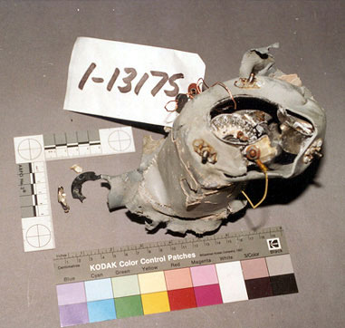
Exhibit 1-5418
Exhibit 1-5418 was a piece of deformed aluminum panel identified as PN 61-3591-3 that formed three sides of the battery pack outer housing. The majority of the black paint on the inner and outer surfaces of the panel was missing; the majority of the aluminum panel exhibited a brownish discolouration. Aluminum panels from other battery packs were heated for comparison purposes; the colour of Exhibit 1-5418 matched those samples heated to 480°C. The electrical schematic and data plate originally attached to the panel were not recovered with the exhibit.
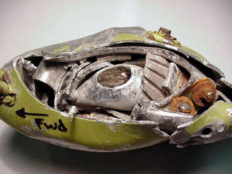
Exhibit 1-2846
Exhibit 1-2846 was the fourth side of the battery pack and consisted of an outer housing assembly PN 61-3179-1, a circuit card assembly PN 61-3379-1, and an inner housing PN 61-3380-1. The exhibit was divided into two pieces; the outer housing contained the J1 and J2 electrical connectors and the attached airframe connectors, and the inner housing was still attached to the circuit board. The deformation of the panels held the two pieces together. The J1 and J2 connector pins had pulled out of their mating components on the circuit board. The black paint on both sides of the inner housing exhibited heat damage. Although the silicon rubber grommets on the inside of the J1 and J2 connectors exhibited impact marks and the J1 grommet was slightly blackened from heat, both grommets remained resilient. The airframe electrical plugs attached to J1 and J2 were blackened from heat and soot exposure. Resolidified aluminum was trapped between the outer surface of the housing and the J2 connector. The melted aluminum was consistent with aluminum alloy 2024.
Most of the J1 airframe connector grommet was not recovered. The remaining grommet remnants inside the connector were an ash colour. The connector was oval in shape as a result of impact damage. Parts of the J1 connector's seven polyimide-insulated, nickel-plated wires (originally attached in a harness) were recovered in lengths varying from 1.5 to 3.5 inches and exhibited mechanical fractures. Only 0.4 to 0.8 inches of wire insulation remained on these wires; the majority of the wire insulation was inside the connector, protected by the grommet material. The polyimide insulation that remained on the wires, just aft of the back shell, was blackened, which corresponded to the oven samples heated to 500°C. The nickel plating on the exposed wire strands remained largely intact. The end of one wire was discoloured and brittle. There was no evidence of melted copper on any of the seven wires. The back shell of the connector did not exhibit any arcing damage.
The J2 airframe connector exhibited similar heat and soot damage as the J1 connector. Seven wire segments varying in length from 0.8 to 5.9 inches were still attached to the connector; one of the wires was a jumper between two pins. The polyimide insulation was missing on these wires from approximately 0.4 inches aft of where the rear rubber grommet had been installed. The polyimide film on the wires within the grommet did not exhibit discolouration as a result of heat damage. The polyimide film remaining aft of the grommet was blackened and corresponded to polyimide film oven samples heated to 500°C. The nickel plating on the exposed wire strands remained intact. The jumper wire was slightly brittle in some localized areas approximately 2 inches aft of the plug. None of these wires exhibited evidence of melted copper. The back shell of the connector did not exhibit any arcing damage. There was considerably more of the silicon rubber grommet remaining in the J2 connector than in the J1 connector. This grommet material was spongy and had lost its resilience.
The black, painted interior surface of the inner housing exhibited a heat transition zone from bottom to top and from left to right with the highest heat zones located at the top and left sides of the housing. The hardware installed along the bottom edge to facilitate installation of the battery pack into the cabin drop-ceiling panel inserts exhibited a dark discolouration on the anodized knobs. The left knob exhibited darker discolouration than the right knob. The cabin drop-ceiling panel inserts had separated from the drop-ceiling and remained attached to the battery pack mounting hardware. The ceiling panel inserts had a darkened, rust-like appearance. The left insert exhibited greater discolouration than the right insert.
The circuit card assembly remained attached to the inner housing. The conformal coating on the surface of the circuit board on the outer side of the housing was missing as a result of heat damage that exposed the printed circuit foil. The left side of the printed circuit board exhibited greater heat damage than the right side. The resins used in the construction of the circuit board had been volatized out of the fibreglass, which was discoloured to black. The resin on the upper edge of the printed circuit board was also volatized out of the fibreglass, which was discoloured to black. The left half of the printed circuit board exhibited greater discolouration as a result of heat than the right side. The two electrical receptacles normally soldered to the printed circuit board had separated from the board and remained attached to the inner housing.
Exhibit 1-8007
Exhibit 1-8007 was the circuit card assembly PN 61-3003-3 that had been attached to the inner surface of the fourth side of the sheet aluminum housing. The circuit board had separated from the housing and exhibited impact damage but little heat damage. The conformal coating remained intact over most of the board. The upper right corner exhibited some localized heat damage to the resin in the fibreglass and discolouration of the fibreglass portion of the printed circuit board as a result of heat. The two screws on the heat sink assembly used to mount the circuit board to the inner surface of the fourth side of the housing remained attached to the heat sink on the circuit board and had pulled out of the housing as a result of impact. One of the four support posts used to mount the circuit board remained attached to the circuit board and had pulled out of the housing as a result of impact. The remaining three support posts were not recovered.
Exhibit 1-5460
Exhibit 1-5460 was the top of the battery pack, a finned, aluminum heat sink assembly PN 61-3177-1 with the circuit card assembly PN 61-3001-3 still attached to it. Since most of the mounting screws between the heat sink cover and the printed circuit board were not accessible as a result of impact damage to the fins on the heat sink cover, the printed circuit board was not separated from the heat sink. The circuit board PN 61-3001-1 exhibited extensive damage; numerous components were displaced. The fibreglass resins had been volatized and the four corners of the circuit board were delaminated and exhibited heat damage.
The heat sink assembly PN 61-3177-1 was deformed and the cooling fins on the top were bent over as a result of impact damage. The fins on the heat sink were deformed, primarily from the back edge of the battery pack toward the forward edge that contained the electrical connectors. The black paint on the heat sink did not exhibit discolouration resulting from heat damage. A considerable amount of material was trapped between the bent fins, including resolidified aluminum, a small bead of copper, and small stones likely captured or wedged in place after the accident. The resolidified aluminum pieces ranged in length from 0.4 to 1.2 inches. One of the pieces had formed into a drop of aluminum. Samples from four of the aluminum pieces were removed and identified as exhibits 1-10590, 1-10591, 1-10592, and 1-10593. It was determined that the four samples were consistent with aluminum alloy 6061. A small, relatively flat copper bead approximately 0.08 inches in diameter was trapped between two fins opposite to the electrical connectors and approximately 1.2 inches in from the batteries edge. The copper bead was identified as Exhibit 1-10598. This resolidified copper bead had a neck-down appearance, which could indicate that the bead had been displaced from the end of an arced wire.
A piece of aluminum (Exhibit 1-5460), which was recovered separately, had resolidified into an elongated and distinctive shape that fit in the space between the fins on the top of a battery pack. The longest leg was approximately 2.1 inches long, the second was 0.9 inches, and the third was 0.02 inches with a small amount of aluminum on top of the two shortest legs. It was determined that the material was consistent with aluminum alloy 2024. It was further determined that this piece of aluminum had been trapped within the fins of the battery pack prior to impact and had subsequently become dislodged.
Flight crew reading lights (Map lights)
Description
Map light wire routing
Power to the captain's and first officer's map lights, briefcase, and chart holder lights and the left and right observer's lights is provided by CB E-12 located on the 28 V DC Bus 2 in the lower main CB panel. The power wires were routed from the lower main CB panel to terminal strip S3-512 located in the avionics compartment. From S3-512, three wires were routed under the cockpit floor to the briefcase and chart holder lights. Four other wires were routed in wire run ABC up the right side of the fuselage to the overhead disconnect panel, to plug P1-442, located behind the upper avionics CB panel in the cockpit. The four wires were then routed from receptacle R5-422& (which mated with P1-442) in wire run AMJ/AMK into the right side of the overhead switch panel housing and continued in wire run AMK, AML, BZC, or BZB inside the housing. The power wire for the captain's map light is in wire run AML; it was routed through, and out of the left oval hole in the overhead switch panel housing. The power wire for the left observer's map light is in wire run BZB, which was routed through this same hole. The power wires for the first officer's and right observer's map lights are routed out of the right oval hole in the overhead switch panel housing.
Examination
First officer's map light
The first officer's map light was still attached to a part of the ceiling liner.
Based on the orientation of the slot in the cockpit ceiling liner at the cutout for the map light assembly, it was determined that this map light was from the right side. The liner was crushed around the broken carrier frame, but the frame remained attached to the liner by screws and nutplates. The metal parts of the light fixture were lightly corroded from immersion in sea water. The carrier frame was fractured, but the light bulb housing that contained the reflector and the lamp was intact. The lamp's glass envelope remained intact, but the filament was fractured into several pieces. It was determined that the filament had been off or cold when fractured. The inner edge of the frame exhibited no evidence of electrical arcing damage. The positive metal spring contact to the base of the light bulb was intact with no evidence of electrical arcing. A three-inch length of 22 AWG polyimide wire remained attached by a ring terminal covered by an insulating sleeve to a terminal stud. The MAPRC insulation topcoat was scraped off in various locations, likely as a result of impact; however, the polyimide film underneath was intact and there was no evidence of any heat or soot damage.
The opposite side of this terminal stud was covered by an orange, rubber-like insulating cap. The cap was still pliable and did not exhibit any heat or soot damage. There was a small split in this cap, the area where arcing, from contact with the U-shaped bracket, had previously been reported. The nut under the cap exhibited no evidence that arcing had occurred between the stud and the bracket. The second terminal connection, adjacent to the terminal with the polyimide wire, was not found. The two white wires connected to the microswitch were both covered with clear sleeving, which exhibited no evidence of soot accumulation.
The cockpit ceiling liner around the fixture exhibited some soot accumulation, but the liner material had not softened. Two ball cups, which cover the front of the map light fixtures, were recovered. Based on their physical deformation, evidence of sooting, and the fact that the right observer's ball cup was captured in its housing, it was determined that these ball cups belonged to either the captain's or first officer's map light.
Right observer's map light
The right observer's map light was installed in an aluminum housing in the horizontal panel located above the right observer's desk, below the lower avionics CB panel at STA 350.
The aluminum housing was crushed and parts of the light fixture were trapped in the housing.
The green primer on the outer surface of the aluminum housing exhibited some soot accumulation, but was not heat damaged. The map light's ball cup, reflector housing, internal wires, and the carrier frame and associated brackets were trapped in the housing. The light bulb and plastic portion of the light socket, including the light socket input terminals and lamp base socket, were not identified. The light head portion of the map light assembly had separated and was not identified. The carrier frame was deformed and did not exhibit any evidence of arcing damage. One orange, rubber-like insulating cap, installed on one input terminal, was visible and was trapped within the crushed aluminum housing. Short lengths of a white and red wire were visible; the white wire exhibited a mechanical fracture, but no evidence of arcing damage.