Associated links (A98H0003)
-
Table of contents
Fuel dumping
Fuel dump description
Fuel dump valves
Description
On the MD-11, two fuel dump valves are located in the left and right trailing edge of each wing, between the flap and outboard aileron. The dump valves are electric motor-driven, gate shut-off valves with an external red handle for manual override capability (for maintenance action only). The fuel dump valve is manufactured by ITT Aerospace Controls Division as PN AV16B1926C. In the event of a loss of electrical power, the valve remains at the last commanded position.
Examination
Left wing
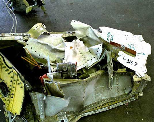
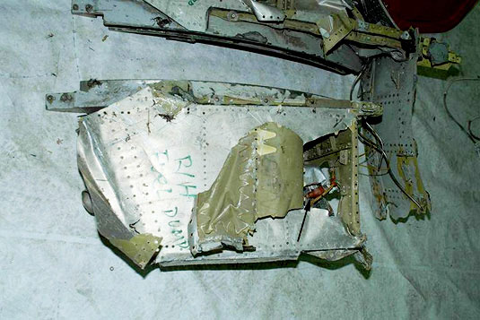
A three-foot-by-four-foot section of left-hand wing structure that contained the fuel dump valve and mast assembly was recovered. The section of structure was bordered by the outboard flap track and a portion of the integral fuel cell wall surrounding the fuel dump outlet. The fuel dump valve body assembly had broken off and had been recovered separately. The electric motor and valve actuator were attached to the structure by the lockwire on the electrical receptacle.
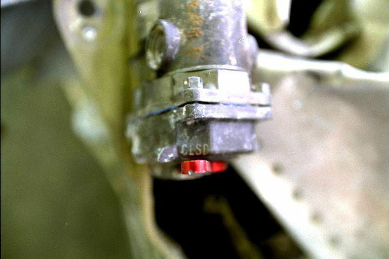
The actuator was recovered with the actuator handle in the CLOSED position. The tip of the handle exhibited a small gouge with a build up of material corresponding to a force that would have biased the handle toward the CLOSED position. The handle had a smaller impact mark on the other side, which would have biased the handle toward the OPEN position. An attempt was made to move the handle and slight pressure was applied. The handle was jammed and did not move.
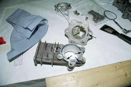
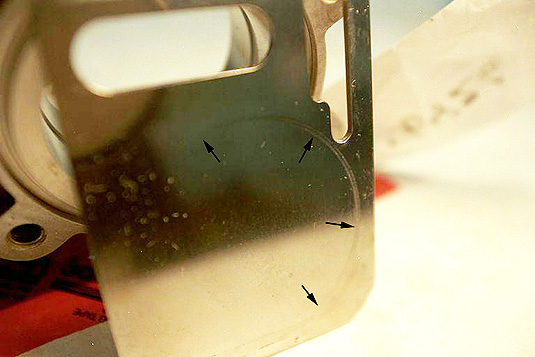
The valve portion of the actuator was recovered separately and was relatively intact. A tag on the valve identified the unit as ITT Aerospace Controls, PN AV16B1926C, SN N 42914. The valve was recovered in the OPEN position, which contradicted the CLOSED position of the actuator. The slide housing cap was removed and water was drained from the housing. Two of the cap screws that held the housing cap in place were impacted, which bent one of the screws and left a small indentation in the housing. The fuel pipe flanges were removed and the "O" ring on the pressure side of the valve had been forced outwards in three locations.
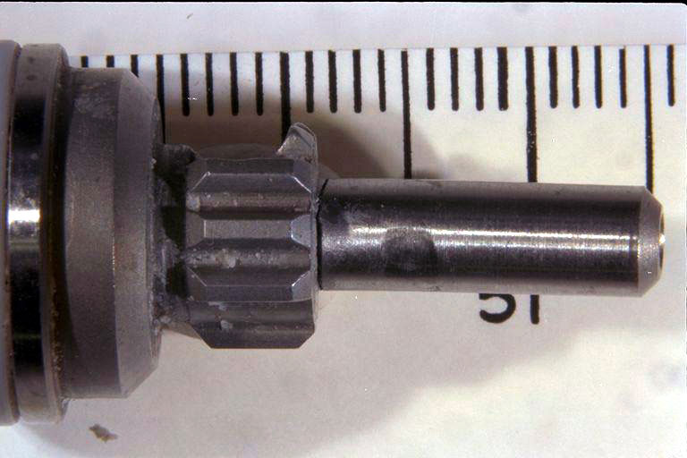
The dump valve was disassembled and the output shaft was found bent.

It appears that the slide gate had been driven upward beyond its normal OPEN position, thereby contacting and bending the output shaft.
One of the slide guides was displaced from its normal position to a position where the end of the supports was extending beyond the end the housing. The slide gate had a circumferential impact mark around the face of the slide from contact with the slide housing.
Right wing
The right wing fuel dump mounting structure, Exhibit 1-5703, was similar to the left wing fuel dump mounting structure, Exhibit 1-3107, in both size and shape.
A tag on the fuel dump valve identified it as ITT Aerospace Controls, PN AV16B1926C, SN N 42915A. The fuel dump valve assembly was bent out of position and the upper half of the electrically driven valve actuator had broken off at the electrical receptacle and was not recovered. The valve actuator output shaft was coupled to the fuel dump valve body. The valve body was intact and the slide gate was in a near-closed (90 per cent) position.
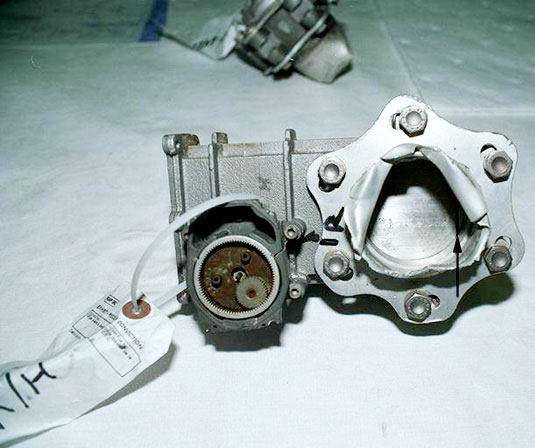
The slide housing cap was removed and jet fuel was drained from the housing. The external red handle was bent back across the housing on the attached half of the valve actuator. The tip of the handle was broken off. The handle was captured in an intermediate position biased toward the CLOSED position, but was not aligned with the position of the slide gate.

The pin securing the handle to the output shaft was sheared from a blow to the handle. The direction of driving force on the handle was from the CLOSED to the OPEN position.
The fuel pipe flanges were removed and the "O" ring seals were in place. The valve was disassembled and no abnormal markings were noted on the internal components

Determination
Left wing
The ruptured flange "O" ring on the pressure side of the fuel dump valve is consistent with fuel in the pipe being forced against a closed slide gate at the time of impact. Such damage to the flange "O" ring would not be expected with the slide gate in the OPEN position.
Based on a stress analysis of the bent output shaft, it was determined that it would have taken approximately 260 lb of force to bend the shaft, well beyond loads expected during normal operation.
The circumferential impact mark around the face of the slide from contact with the slide housing is consistent with the slide being in the CLOSED position.
Based on the damage to the "O" ring, combined with the circumferential mark on the slide gate, the bent output shaft, and the position of the actuator lever, it was determined that the fuel dump valve was in the CLOSED position at the time of impact and had been driven open by impact forces.
Right wing
There was no damage to the valve indicating that the valve was in a position other than the CLOSED position at the time of impact. The damage to the actuator handle is consistent with the valve being driven partially open by a blow to the handle. The lack of damage to the flange "O" ring seals, particularly on the pressure side of the valve, is inconsistent with the damage observed on the left fuel dump valve; however, this inconsistency may be related to the impact angle and impact forces.
Fuel dump electrical power supply
Description
The DUMP switch controls the fuel dump operation through the left and right fuel dump valve control relays. The fuel dump valves require power from their respective fuel dump valve control CBs to either open or close. The power for the left fuel dump valve comes from the 28 V DC Bus 1 through CB B1-458 located at position H-22 on the upper main CB panel.The power for the right fuel dump valve comes from the 28 V DC Bus 3 through CB B1-457 located at position K-22 on the upper main CB panel. The power input and output wires to the DUMP switch are routed behind the avionics CB panel and pass through the right-side oval opening in the overhead switch panel housing.
The FSC monitors, but does not control, fuel dump operations. The FSC is located below the cockpit floor on the main avionics rack in the avionics bay. The FSC is equipped with a dual power source. Channel A power is supplied by the 28 V DC Bus 1 through CB B1-1582 located at position H-26 on the upper main CB panel. The circuitry for Channel A does not traverse any known area of fire damage. Channel B power is supplied by the right emergency 115 V AC bus through CB B1-1583 located at position G-23 on the overhead CB panel. Power from the CB is provided via wire B201-325-20 on wire runs AMP, AMK, and AMH to P1-238 located behind the upper avionics CB panel. This wire is routed through an area of known fire damage. From that area it proceeds down the right side of the aircraft via wire B203-911-20 on wire run AAC to the main avionics rack.
Examination
The power input and output wires from the DUMP switch were not identified. However, the wires extending from connectors P1-420 and P1-421 on the overhead disconnect panel to the right-side oval opening in the overhead switch panel housing progressed through a known area of high heat.
Determination
Based on known fire damaged areas, the only wires or CBs in the fuel dump system that might have been affected by fire or heat were the wire and the CB supplying power to the FSC Channel B and the power input and output wires from the DUMP switch that were routed in the area of the overhead disconnect panel. The loss of power to the FSC Channel B would not affect fuel dump operations as the FSC only provides a monitoring function. However, the opening or shorting of the input or output wires from the DUMP switch would result in the loss of control of one or both fuel dump valves as they would stay in their last commanded position.
Flight data recorder and ATC information on fuel dump
Description
The DFDR records Aircraft Gross Weight and Total Fuel quantity. The last Aircraft Gross Weight value was recorded at 0124:56. At 0124:53, the crew indicated to ATC that they were starting to dump fuel. Four seconds later at 0124:57, ATC informed SR 111 that they would contact them in just a couple of miles; SR 111 acknowledged the transmission and indicated that they were declaring an emergency. At 0125:16, ATC cleared SR 111 to commence the fuel dump; this transmission was not recorded on the CVR. SR 111 did not respond and no further communications were received from the aircraft.
Examination
The DFDR information was examined to determine whether the crew may have started the fuel dump prior to notifying ATC about their intentions to dump fuel. The aircraft C of G was plotted against its gross weight (see chart of "Centre of Gravity (C of G) data plot"); an increase in the slope of the plot (a faster drop in Gross Weight) was apparent for the last two data points. The data was subsequently compared with aircraft operational data.
Determination
Based on the data comparison, it was determined that the faster drop in Aircraft Gross Weight was likely the result of the aircraft levelling off at 10 000 feet and the engines coming up above idle thrust. The increased fuel flow to the engines would result in a corresponding drop in fuel quantity and gross weight. Had the fuel dump been initiated, the slope of the plot would dramatically increase.
Because Aircraft Gross Weight DFDR information was recorded after the crew indicated to ATC that they were starting to dump fuel, it could not be established from DFDR information whether the crew had initiated a fuel dump at that time. An analysis of the aircraft C of G versus gross weight plot indicated that fuel dumping had not been initiated prior to the loss of the DFDR data.
Fuel dump rate
Description
At the time that the DFDR was lost, the aircraft weighed approximately 230 metric tonnes. At a maximum dump rate of 2 600 kg/min (2.6 metric tonnes/min), it would have taken a minimum of 11.7 minutes to dump the 30 metric tonnes of fuel needed to reach the aircraft's maximum landing weight of 199.58 metric tonnes (as preselected on the aircraft's FMS), and about 4.5 minutes to reach the maximum overweight landing weight of 218.4 metric tonnes. The aircraft crashed 5 minutes, 41 seconds, after the loss of the DFDR. If the fuel dump had commenced, the main tank fuel levels were such that the fuel dump would not have been terminated automatically by reaching the tank low level condition.
It is not known whether the crew selected the FUEL INIT Page on the MCDU to change the auto dump level as programmed into the FMS; this page is not recorded on the DFDR.
Determination
If fuel dumping had been initiated by the crew after the loss of the DFDR, there would not have been sufficient time to dump the fuel required to reach the maximum landing weight as preselected in the FMS. Without information indicating that the crew had reselected the auto dump level in the FMS, fuel dump operation should have been ongoing at the time of impact. A loss of electrical power will not close the fuel dump valves. To terminate fuel dump prior to reaching the auto dump level, if fuel dump had been initiated, crew action would have been required.
Fuel dump determination
There was no evidence indicating that fuel was being dumped prior to the loss of the DFDR. If a fuel dump was initiated after the loss of the DFDR, it would have taken a minimum of 11.7 minutes for the FSC to automatically stop the fuel dump once landing weight was achieved. The fact that the fuel dump valves were closed at the time of impact indicates that either the fuel dump was initiated after the loss of the DFDR and then manually terminated before impact, or that the fuel dump was not initiated. Because the valves must be electrically opened or closed, a loss of electrical power to the valves after the dump has been initiated will cause the valves to remain open. If the SMOKE ELEC/AIR selector was used prior to or during the fuel dump, the switch would have to have been rotated through to the 2/3 OFF or the NORM position prior to impact in order to close both valves. Based on an examination of the known fire damaged wiring, it could not be determined whether the fuel dump valves were operational at the time of impact. The CLOSED position of the auxiliary tank fill/isolation valve could indicate that fuel dumping had taken place. Based on the analysis of the fuel pumps, it was determined that the Tank 2 right aft boost pump was off, which is consistent with the CLOSED position of the fuel dump valves, as fuel dumping takes precedence over an engine shutdown.
Crew initiated fuel dump – Closing of auxiliary tank fill isolation valve
If fuel dumping was initiated after the loss of the recorders, the FSC would close the auxiliary tank fill isolation valve (opened for tail fuel forward transfer), redirecting tail tank fuel to the upper auxiliary tank. As there would not be any fuel in the auxiliary tank at this time, fuel would be dumped overboard from the main fuel tanks only, at a rate of approximately 5 200 lb/min, supplied by the 10 main tank fuel pumps. The auxiliary fuel tank would then start to be filled from the tail tank and when the tank quantity reached more than 2 100 lb, the FSC would turn on the two upper auxiliary tank pumps to increase the fuel dump rate to 6 000 lb/min. Given the amount of fuel on board, fuel dumping would take almost 12 minutes to bring the quantity down to the aircraft's maximum landing weight. As the aircraft crashed 5 minutes, 41 seconds after the loss of the recorders there would not have been time for the fuel dump to have been automatically terminated by reaching the pre-programmed dump setting or the tank low-level condition. However, the fact that the fuel dump valves were found in the CLOSED position indicates that if the crew initiated a fuel dump they terminated it before the time of impact.
When a fuel dump is terminated the FSC determines which mode to go into next. If a fuel dump was initiated during tail tank fuel transfer forward and lasted for more than three minutes, the upper auxiliary tank would most likely contain more than 2 100 lb of fuel and the FSC would enter into a reschedule mode. In this mode, the FSC does not re-open the auxiliary tank fill isolation valve and continues to transfer fuel to the upper auxiliary tank as long as the quantity in the tank stays above 1 800 lb. The tail tank fuel flow rate into the upper auxiliary tank is about the same as the transfer of fuel out of the tank; therefore, the reschedule mode would continue until the tail tank is empty. As there was insufficient time prior to the time of impact to empty the tail tank, the auxiliary tank fill isolation valve would remain closed.
Loss of electrical power to the valve after fuel dump initiated
If a fuel dump was initiated, closing the auxiliary tank fill isolation valve, the fire could have compromised the wiring or CBs resulting in the auxiliary tank fill/isolation valve remaining closed.
Fuel pump operation with respect to fuel dumping
Based on the FADEC fault data, it was determined that Engine 2 was shut down using the FUEL switch. Using this switch would shut off the Tank 2 fuel boost pumps. As fuel dumping takes precedence over an engine shut down, the fuel pumps in the tank corresponding to the shut-down engine would not be shut off. The Tank 2 right aft boost pump being off is consistent with Engine 2 shut down and the fuel dump valves being in the CLOSED position. The Tank 2 transfer pump exhibited sufficient rotational damage to determine that it was running at the time of impact. This pump would come on with Engine 2 shut down if there were a fuel imbalance between tanks 1 and 3, and Tank 2, as would be expected with the upper auxiliary tank supplying fuel to Tank 2.
Based on the available physical evidence and CVR data, it was determined that the crew initiated a fuel dump between the time the recorders and ATC communications were lost and the time of impact. The fuel dump was terminated by the crew prior to impact.
Either the fuel dump was occurring for at least three to four minutes to allow sufficient fuel to enter the upper auxiliary tank to reschedule the fuel system to keep the auxiliary tank fill isolation valve closed or the fire tripped both auxiliary tank fill isolation CBs after the fuel dump was initiated. If the first scenario is correct, the fuel dump was terminated one to two minutes prior to the time of impact or at approximately the same time as Engine 2 was shut down.