2 November 2021
City Manager
City of Ottawa
110 Laurier Avenue West
Ottawa, Ontario K1P 1J1
Subject :
Rail Safety Advisory letter 617-03/21 (TSB occurrence R21H0121)
Work procedures for Ottawa Light Rail Transit vehicle maintenance
On 14 September 2019, Ottawa Light Rail Transit (OLRT) Stage 1 commenced operation in Ottawa, Ontario. The vehicle selected for OLRT operations was the Citadis Spirit light rail vehicle (LRV) manufactured by Alstom and mounted on Iponam bogiesFootnote 1 (figures 1 and 2). OLRT connects 2 LRVs together and operates them as 1 commuter train.
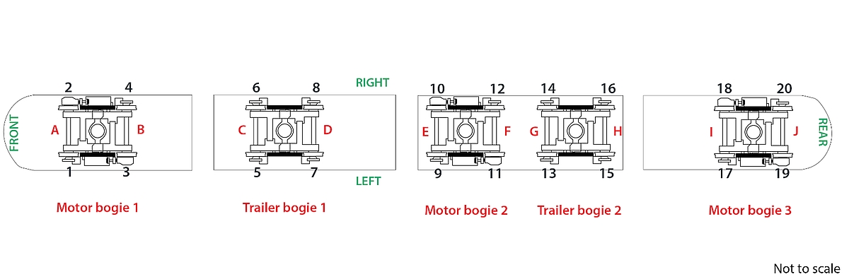
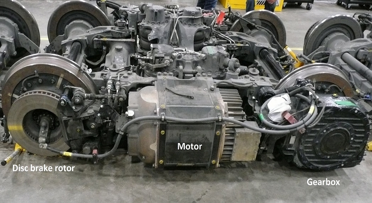
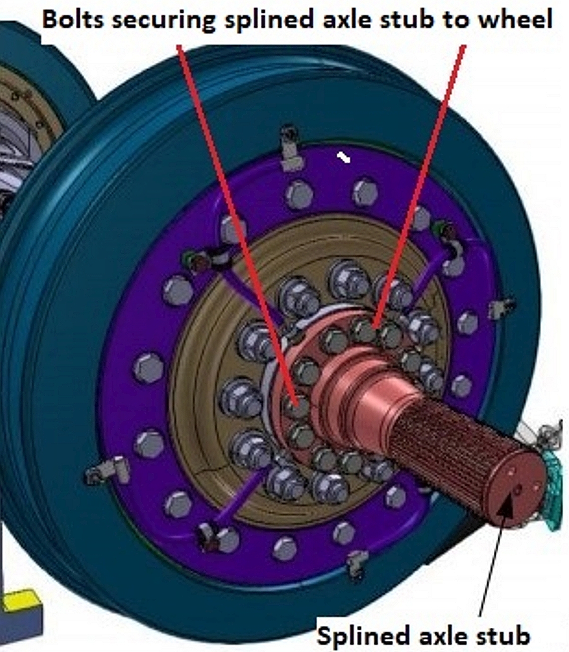
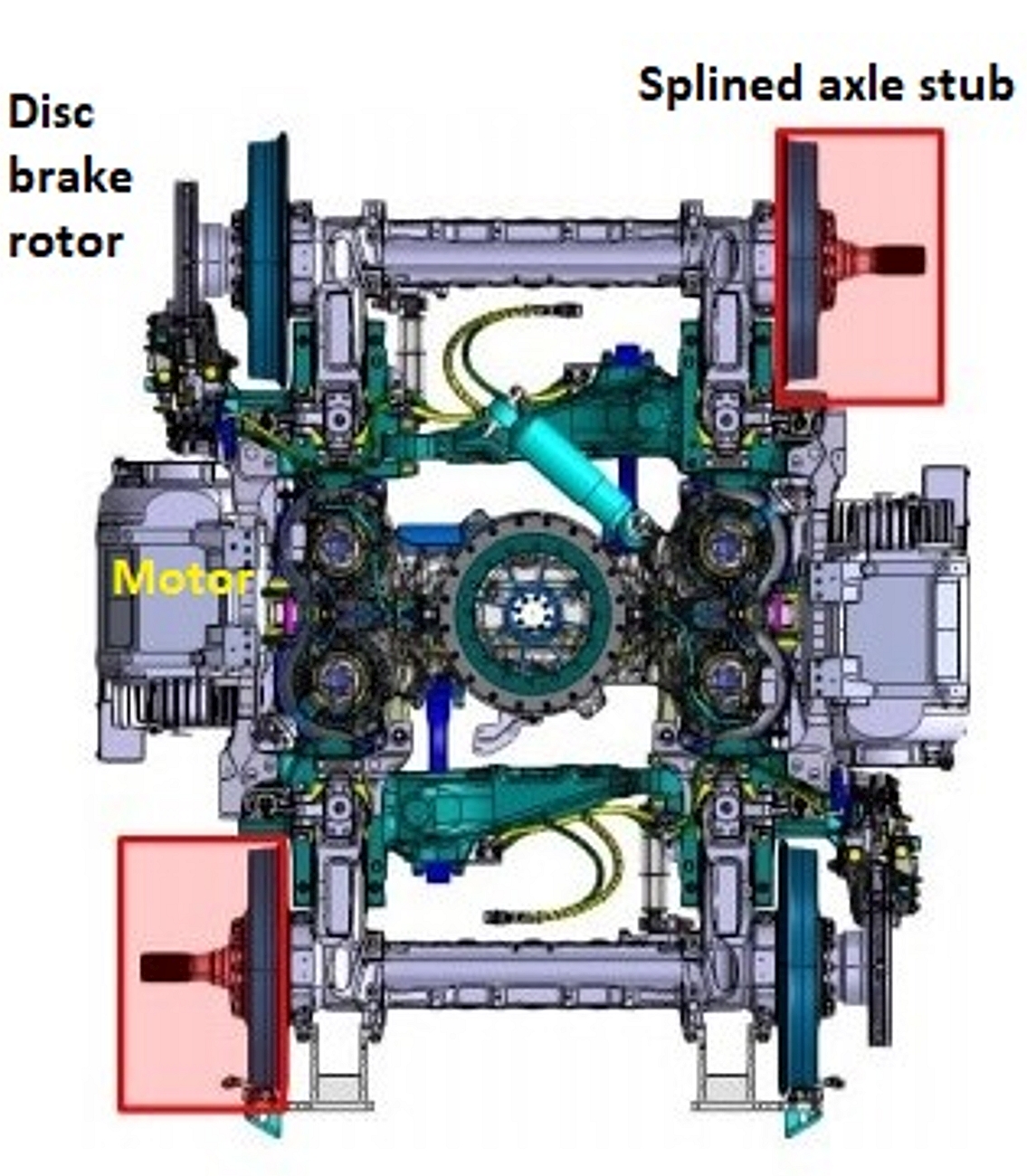
Each motor bogie is equipped with 2 motors—1 on each side of the bogie. Power from each motor is transmitted to a drive wheel through a gearbox that interconnects with a splined axle stub, also referred to as a reducer hub, which is secured to the wheel hub with 12 bolts (Figure 3). Disc brake rotors are attached to the wheel hub opposite the drive wheel of each motor bogie wheel set (Figure 4), and to each wheel of the trailer bogies. The rotors are also secured to the wheel hub with 12 bolts.
Ottawa Light Rail Transit main-track train derailment on 08 August 2021
On 08 August 2021 at about 2034,Footnote 2 an eastbound OLRT commuter train was proceeding from the north track to the south track over the SW-302 south crossover switch at a speed of about 30 km/h. Subsequently, it derailed about 90 m east of Tunney’s Pasture Station in Ottawa. It was determined that the No. 3 wheel on LRV 1119 severed from the axle due to a previously undetected catastrophic roller bearing failure and subsequent axle journal burn-off. There were no passengers on board at the time of the occurrence (TSB occurrence No. R21H0099).Footnote 3
Following the LRV 1119 derailment, the entire OLRT LRV fleet was grounded while cartridge assembly axial end play clearance measurements were completed on the fleet (20 per LRV). Measured clearances in excess of 0.1 mm required the cartridge assembly to be replaced with a new assembly. A new periodic inspection was implemented to measure axial end play clearance on all LRVs every 7500 km, on an ongoing basis.
The initial fleet inspection identified 1 destroyed cartridge assembly on LRV 1119 and 17 other loose cartridge assemblies on 9 other LRVs with measured clearances that ranged from 0.12 mm to 0.89 mm. During this fleet inspection, 3 loose cartridge assemblies were identified on LRV 1121 in the motor bogie 2 (BM2) No. 11 wheel position and in the motor bogie 3 (BM3) No. 17 and No. 19 wheel positions.
LRV 1121 was held at the OLRT Belfast Yard Maintenance and Storage Facility (MSF) for repairs where the 3 suspect LRV 1121 cartridge assemblies were replaced between 08 September and 11 September 2021 (Appendix A).
LRV 1121 refurbishment work
On 08 September 2021, in preparation for refurbishment work, BM2 and BM3 were removed from LRV 1121.
On 09 September 2021, work commenced. All preparation work was done by Alstom employees, including removal of gearbox, axle spline stub, and disc brake assemblies, before Texelis employees conducted their work to replace the cartridge bearing assemblies.
After the Texelis employees completed their work, the bogies were re-assembled by Alstom employees. The Alstom work included the installation of new bolts with the application of the required torque for the remaining bogie assembly.
Bolts that secure the splined axle stubs, disc brake rotors and wheels have torque requirements. An electronic torque gun (torque gun) that captures data automatically is used to complete the torqueing of these bolts.
At 2300 on 09 September 2021, the afternoon shop staff finished their shift without realizing that the bolts securing the splined axle stub to the wheel hub in BM2, No. 11 wheel position, had not been adequately torqued or advising the next shift of work that was outstanding.
On 10 September 2021, the morning shift continued with the refurbishment, completed the torqueing of the disc brake rotors, reinstalled BM2 and BM3 and, then sent LRV 1121 to MSF 1 for final inspection, which included a check of all gearboxes for oil leaks. Subsequently, LRV 1121 was released from MSF 1 on 13 September 2021 and resumed passenger service the next day.
The accident
At about 1200 on 19 September 2021, westbound OLRT commuter train 1121-1138 was proceeding on track 1 when BM2 on the trailing LRV 1121 derailed near the mid-point of the north platform of Tremblay Station as it departed the station. The train continued for about 1400 feet, over the rail bridge that traversed Riverside Drive. The derailed bogie condition was not detected, nor noticed by the operator. Subsequently, the train went into emergency and came to a stop just west of the rail bridge. The train, which had 12 passengers and 1 operator on-board at the time, was evacuated once it was safe to do so. There were no injuries.
Site examination
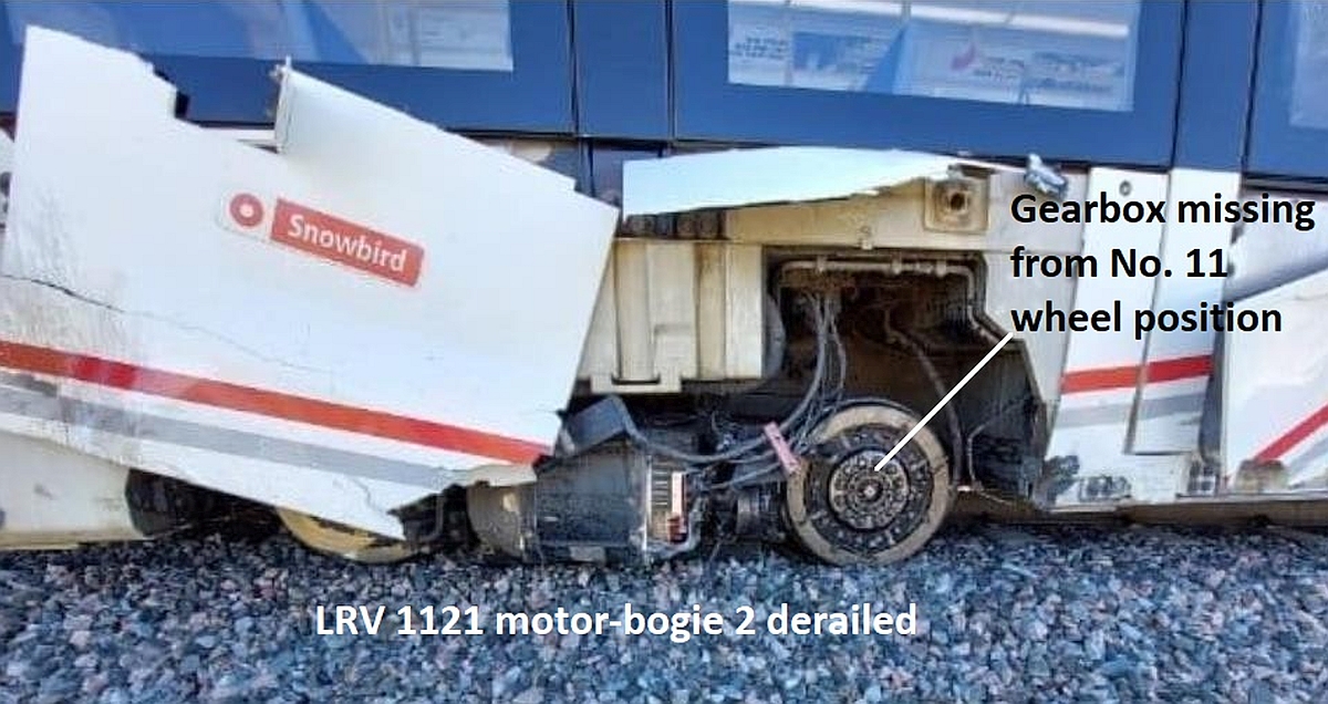
BM2 on LRV 1121 had derailed to the north side of the track. The motor gearbox from the No. 11 wheel position had detached from the wheel and was missing (Figure 5).
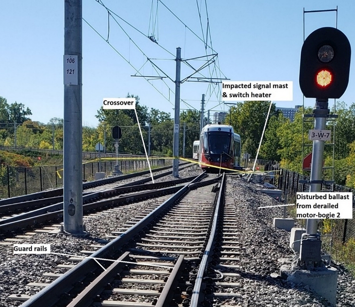
During the derailment, LRV 1121 had contacted and destroyed a signal mast and switch heater that were adjacent to, and north of, track 1 (Figure 6).
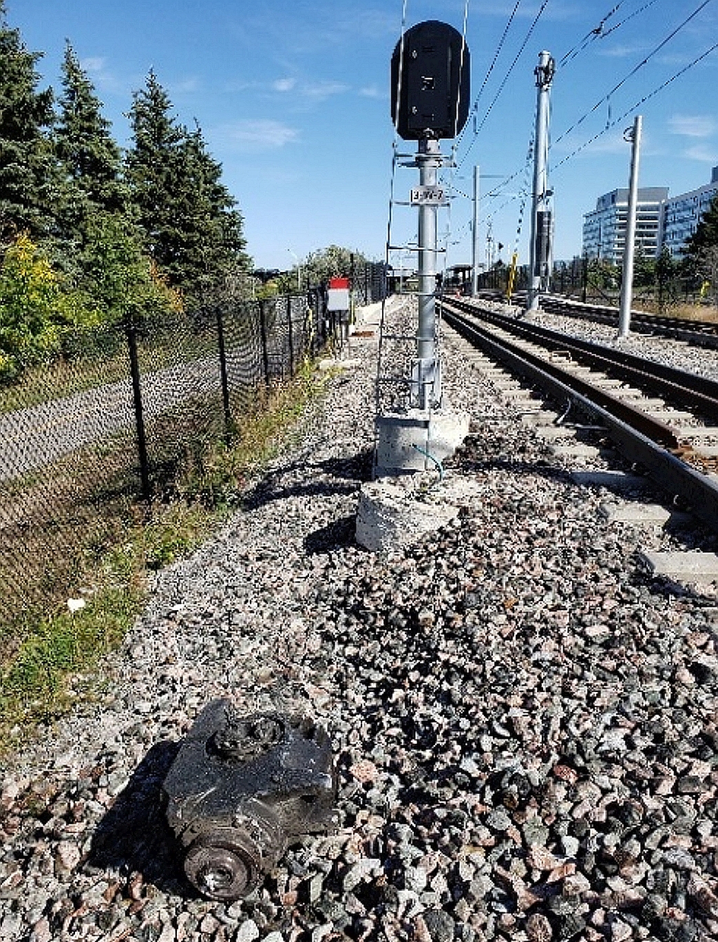
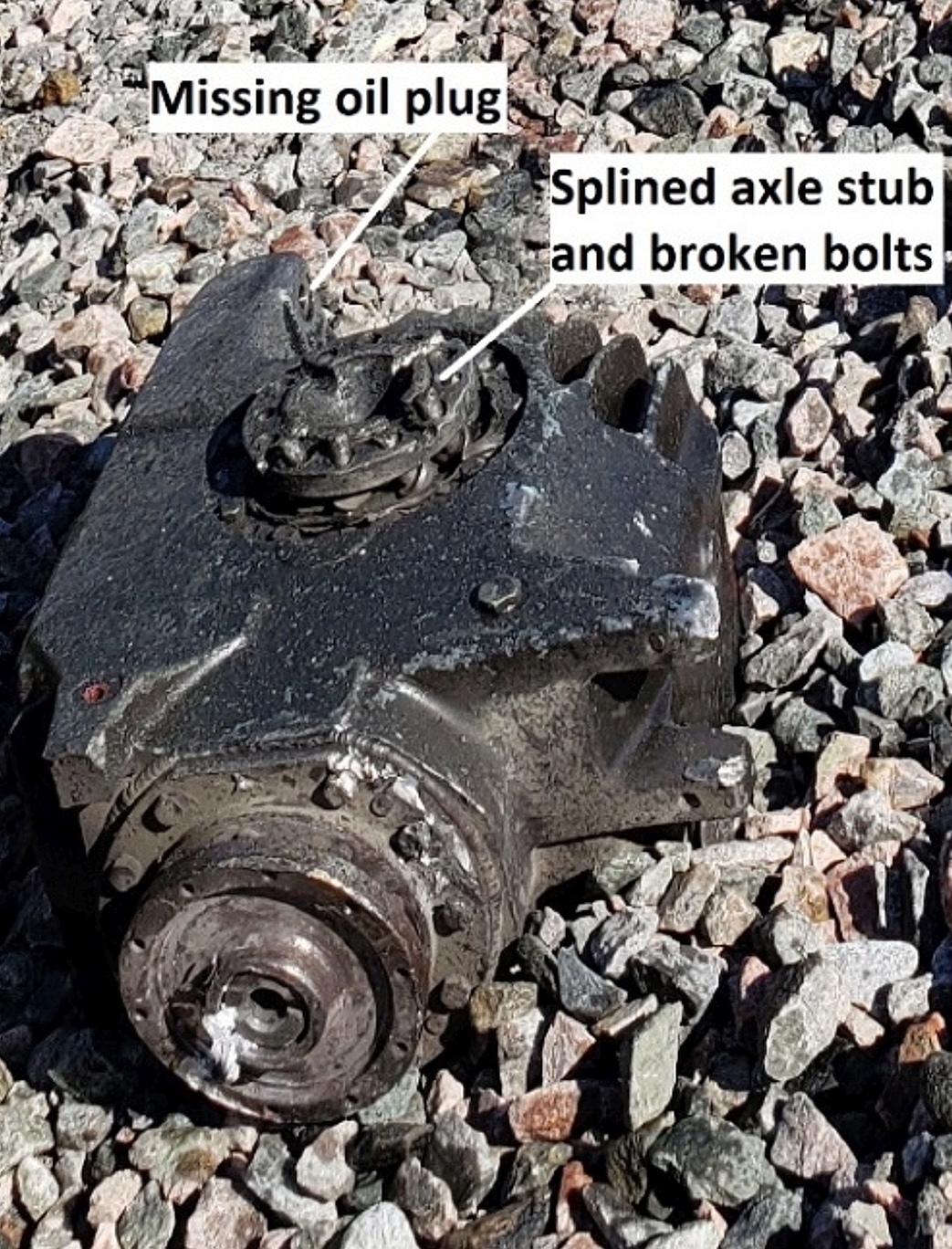
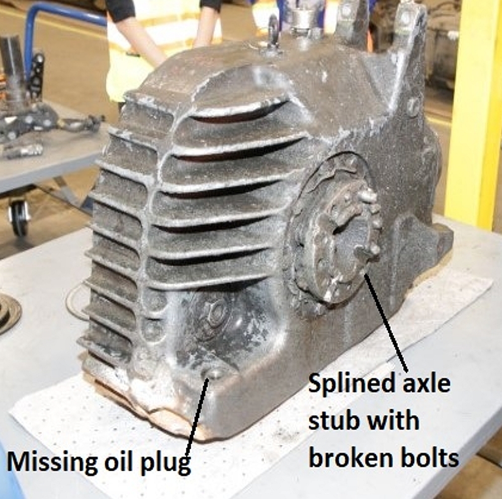
From LRV 1121 eastward, the ballast along the north side of track 1 was disturbed for about 1400 feet. The gearbox from the BM2 No. 11 wheel position was located on the ballast just north of the track. An oil plug was missing from the gearbox (Figures 7 and 8).
The disturbed ballast extended up to and alongside the north platform of Tremblay Station terminating at several displaced ties near the middle of the platform, which was likely the initial point of derailment. Scrapes were observed along the side of the north passenger platform at Tremblay Station. The damage was consistent with similar damage observed on the north side passenger door threshold just above the BM2 location of LRV 1121.
Between Tremblay Station and the previous station to the east (St. Laurent Station), impact marks were observed at sporadic intervals on the rail ties, rail clips and clip holders. A number of rail clips had been fully dislodged all along the north side of the north rail. The frequency of the marks increased approaching the east end of Tremblay Station. All of the damage was consistent with impacts from contact with a mechanical component from LRV 1121.
At the time of the occurrence, LRV 1121 had accumulated approximately 800 km since the cartridge assembly refurbishment for BM2 No. 11 wheel position. Subsequently, LRV 1121 was sent to the OLRT MSF for detailed examination of BM2 and BM3, which both had been recently refurbished.
After LRV 1121 arrived at the MSF, BM2 and BM3 were removed from LRV 1121 at MSF 2 and quarantined.
Examination of gearbox from the LRV BM2 No. 11 wheel position
On 28 September 2021, the TSB and Alstom conducted a joint examination of the 2 bogies.
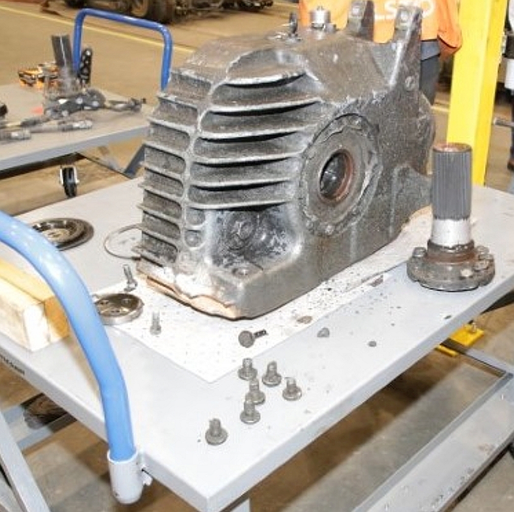
The splined axle stub is normally secured to the wheel hub with 12 fine-thread, class 12.9 M16x1.5 bolts. In this case, all 12 of the bolts from the BM2 No. 11 wheel position had failed (figures 9 and 10).
The recovered bolts were examined at the TSB laboratory with the following observations:
- Several bolts were significantly deformed. This deformation was only possible if the mating surfaces of the splined axle stub and wheel hub had separated.
- A total of 3 threaded portions of the bolts were recovered from within the wheel hub mounting holes. The failed end of 1 bolt was examined using a low-power optical microscope and a scanning electron microscope. The fracture had initiated at the root of a thread and exhibited beachmarks that progressed uniformly from the outside in, in a radial manner, characteristics that are typical of high-stress, low-cycle fatigue.
Changes in stress loading are required in order for fatigue to develop. If the bolts that secured the assembly had been fully torqued, such loading changes would not have occurred.
Torque requirements and records
The procedure for torqueing the bolts securing a splined axle stub to a wheel hub is as follows:
- Torque by hand to 50Nm
- Start torqueing program with automated torque gun and torque bolts to 150Nm
- Torque bolts to an additional 135 degrees of rotation
The procedure to install and torque these bolts is one that could result in a torque-to-yield situation, which is common when it is essential that a consistent and constant clamping force be maintained. The torque gun can recognize if a bolt has already been torqued and requires a maximum/minimum criteria before moving to the next step of the process. This is indicated to the employee with a red or green light. Final rotation angle and final torque are recorded for all automated steps. This procedure causes permanent deformation to each fastener, and renders them unusable for subsequent assemblies. Alstom requires that bolts not be reused, although reuse of bolts on this component was previously noted by Alstom on 19 October 2020.
A post-accident review of the torque gun data revealed that data for one of the three splined axle securement operations was missing. This missing data was later attributed to the BM2 No. 11 wheel position after employees physically checked the bolts securing the splined axle stub in BM3 No. 17 wheel position and BM3 No. 19 wheel position and determined that the required torque was applied.
The torque gun requires a train ID, bogie ID and employee ID before a work procedure is selected from a work order. This information is often not readily available as part of the work order paperwork. Consequently, staff scan values off of an old work order that was left at the torque gun workstation. In this case, the work order for LRV 1121 was unavailable; therefore, staff scanned an old work order and the work was recorded as being for LRV 1125.
The employee ID is picked from a list of bar codes. The codes on the list are placed close to each other, which presents a potential risk that an employee could select the wrong ID.
It is also possible to select the torqueing of multiple components with a single operation. For example, it is possible for the worker to select a “4WHEELTIGHTENING” procedure, which allows for all 48 bolts on a total of 4 wheels to be tightened in succession rather than doing each wheel individually and recording the torque values that were applied to a particular wheel position.
The torque gun has the capability to record train, bogie, employee and the specific operations being performed, but the information entered by the employees is not always consistent and/or correct for the task. This limits the possibility for any accurate traceability of the work performed, which is a fundamental element of any quality control program.
Work procedures and oversight
There were no impact marks observed on the gearbox surface in the area of the missing oil plug. Only 1 litre of the 6.1 litres of oil required to fill the gearbox oil was recovered. Although Alstom procedures required that the oil fill plug be torqued and the head of the plug be marked, no such indications were observed. Although gearboxes are to be inspected for oil leaks prior to release from MSF 1, TSB observations suggest that Alstom procedures were not followed and there was likely no oil plug installed at the time of the LRV 1121 inspection at MSF 1.
The assembly of a bogie has a written procedure. While there is a checklist and sign-off required for re-attaching a bogie to an LRV, there is no checklist with sign-off documentation required for employees that complete many of the critical tasks for bogie and wheel assembly. There was also no sign-off required for the supervisory or quality control personnel that should be providing oversight.
The removal and reassembly of the splined axle stub are part of the written procedure for wheel replacement, which is printed in a laminated booklet that employees are expected to use for reference. Alstom shop staff appear to be familiar with the sequential steps but often perform the work out of order and the steps, when completed, are not consistently documented.
Although the splined axle stub installation, which includes torqueing the bolts that secure the splined axle stub to the wheel hub, is among the final steps in the procedure, Alstom staff routinely take the wheel off without removing the splined axle stub. A review of the torque data revealed that the splined stub axles are often torqued before the wheels are. Conducting work procedures out of a defined order presents a risk that critical steps in the process, such as torqueing the bolts that secure the splined stub axle to the wheel hub, can be missed.
Alstom’s process requires that all bolts for which a torque is specified are to be identified with a suitable marker/indicator after torqueing. However, a review of some of the overhauled components also revealed a lack of consistency in the “marking” of torqued bolts.
At the time the work was performed, it was reported that there was also minimal supervisory and/or quality control personnel oversight of the refurbishment work performed. Although the wheel torques were recorded on a paper, there were no such records for any other component with torqueing requirements and no supervisory or quality control sign-off was required.
A robust quality control system features process and assembly records or checklists for the assembly or reassembly of safety critical components. Each step should be documented, signed off on and verified by supervisory and/or quality control staff that the work was performed in the correct order and completed as required. This is particularly important when a job is started by one work shift and handed off to another.
Conclusion
The 12 bolts that secured the splined axle stub to the BM2 No. 11 wheel hub of LRV 1121 were not adequately torqued when installed during refurbishment. LRV 1121 was then allowed to enter service without a complete set of torque data or Alstom verification that all work was complete. The lack of applied torque led to the failure of all 12 retaining bolts after only about 800 km of service. Failure of the bolts resulted in a disconnection of the drivetrain from wheel position No. 11. Components from the disconnected drivetrain subsequently dropped from the LRV and contacted the track infrastructure, which ultimately caused the derailment near the middle of the north passenger platform at Tremblay Station.
LRV 1121 was repaired and released from a shop only to have a safety-critical component fail and cause a serious accident within 5 days of its release. This accident has demonstrated that there can be serious consequences resulting from the inconsistent and incomplete maintenance of safety-critical components on an LRV in commuter passenger service. Therefore, OLRT may wish to conduct an in-depth review of all work performed on safety-critical components to confirm that procedures are followed and that there is sufficient oversight in place to prevent a similar occurrence from happening again.
The TSB would appreciate being informed of what action, if any, will be taken in this regard and further advised of the outcomes of such action taken.
Yours sincerely,
Original signed by
Paul Treboutat
Director, Investigations (Rail/Pipeline)
Transportation Safety Board of Canada
CC.
-
Director General, Rail Safety
Transport Canada -
Project Manager
Alstom Transport -
Chief Executive Officer
Rideau Transit Maintenance - General Manager
Transit Services City of Ottawa -
Chief Safety Officer
Safety, Compliance, Training and Development Transportation Services
City of Ottawa
Appendix A – TSB estimated timeline of work performed on LRV 1121
Notes:
- Times below are estimated based on results from TSB investigation activities.
- Alstom staff at the OLRT MSF 1 building generally handle inspections and routine maintenance while staff at the MSF 2 building looks after retrofits and refurbishments.
- Although OLRT LRVs only have 10 axles (figure 1), Alstom refers to BM3 as containing axles 11 and 12. To minimize confusion, the information has been modified to identify axles 9 and 10 with wheel positions No. 17 to No. 20.
- Motor-Bogie 2 (BM2) axle F (6) includes wheel positions No. 11-No. 12.
- Motor-bogie 3 (BM3) axle I (9) includes wheel positions No. 17-No. 18 and axle J (10) includes wheel positions No. 19-No. 20.
| Date (2021) | Estimated time | Action |
|---|---|---|
| 11 August | N/A | Fleet inspection identifies 3 loose cartridge assemblies on LRV 1121.
|
| 08 Sept | N/A | MSF 2 - BM2 & BM3 removed from LRV 1121 |
| 08 Sept | N/A | Axles dismantled |
| 09 Sept | 0600 | Alstom MSF 2 morning crew begins workday |
| 09 Sept | N/A | Texelis changes BM3 axle 10 cartridge assemblies (wheel positions 19–20) |
| 09 Sept | N/A | Texelis changes BM3 axle 09 cartridge assemblies (wheel positions 17–18) |
| 09 Sept | 1400 | Alstom MSF 2 afternoon shift begins workday |
| 09 Sept | N/A | Texelis changes BM2 axle 06 cartridge assemblies (wheel positions 11–12) |
| 09 Sept | N/A | Splined axle hub bolts tightened BM3 axle 09 - wheel position No. 18 |
| 09 Sept | 1930–2000 | Dinner break |
| 09 Sept | 2025–2040 | Splined axle hub bolts tightened BM3 axle 10 – wheel position No. 19 |
| 09 Sept | 2050–2240 | Wheel bolts torqued - BM3 wheels No. 17 to No. 20 and BM2 wheels No. 11-No. 12 |
| 09 Sept | 2300 | Alstom MSF 2 afternoon shift completes workday |
| 10 Sept | 0600 | Alstom MSF 2 morning shift starts workday |
| 10 Sept | 0600–1100 | Disc brake rotors torqued - BM2 axle 06 wheel position No. 12, BM3 axle 10 wheel position No. 20 and BM3 axle 09 wheel position No. 17 |
| 10 Sept | N/A | Post axle clearance check |
| 10 Sept | N/A | MSF 2 BM2 and BM3 installed back in LRV 1121 – refurbishment complete |
| 10 Sept | N/A | LRV 1121 sent to MSF 1 for final inspection |
| 11 Sept | N/A | MSF 1 final inspection of LRV 1121 – Gear boxes checked for leaks |
| 13 Sept | N/A | LRV 1121 released. |
| 14 Sept | N/A | LRV 1121 back in service – accumulated 11 kms |
| 14–18 Sept | N/A | LRV 1121 travelled a total of 753 kms |
| 19 Sept | 0740 | LRV 1121 & LRV 1138 resume daily service as train 21/38 |
| 19 Sept | 1200 | LRV 1121 derails in Tremblay station after traveling about 800 km following refurbishment and release back into service |