Main-track train derailment
Main-track train derailment
Canadian Pacific Railway Company
Freight train 603-897
Mile 32.75, Lanigan Subdivision
Silton, Saskatchewan
The Transportation Safety Board of Canada (TSB) investigated this occurrence for the purpose of advancing transportation safety. It is not the function of the Board to assign fault or determine civil or criminal liability. This report is not created for use in the context of legal, disciplinary or other proceedings. See Ownership and use of content. Masculine pronouns and position titles may be used to signify all genders to comply with the Canadian Transportation Accident Investigation and Safety Board Act (S.C. 1989, c. 3).
Summary
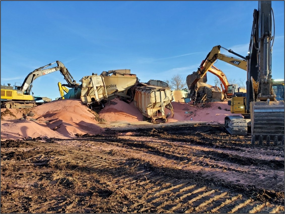
At about 0500 Central Standard Time on 16 October 2021, Canadian Pacific Railway Company (CP) freight train 603-897, a unit train hauling 200 covered hopper freight cars loaded with potash, was proceeding southward at 38.6 mph on the CP Lanigan Subdivision when it experienced a train-initiated emergency brake application at Mile 31.58, near Silton, Saskatchewan. The head-end locomotive came to a stop at Mile 31.18. Subsequent inspection by the conductor determined that 27 freight cars had derailed near Mile 32.75. Many of the derailed cars had come to rest in a large pile, were breached, and had released their contents. There were no injuries and no dangerous goods were involved.
1.0 Factual information
On 15 October 2021, a Canadian Pacific Railway Company (CP)Footnote 1 train crew was ordered for 2245Footnote 2 in Saskatoon, Saskatchewan, to operate unit trainFootnote 3 603-897 (the train) from Sutherland Yard (Saskatoon) to Regina, Saskatchewan, via the Sutherland and Lanigan subdivisions. The train crew consisted of a locomotive engineer and a conductor. Both crew members were qualified for their respective positions, met fitness and rest requirements, and were familiar with the territory on which they operated.
The train was set up to operate in a 1-1-1 distributed power configuration composed of head-end controlling locomotive CP 8007, 100 loaded covered hopper freight cars, mid-train remote locomotive BNSF 6208, another 100 loaded covered hopper cars, and tail-end remote locomotive CP 9808 (Figure 1).
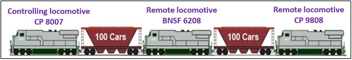
Each of the covered hopper cars was 47 feet long and had a heavy axle load 286 000-pound gross rail load capacity. The train was 9625 feet long and weighed 28 525 tons.
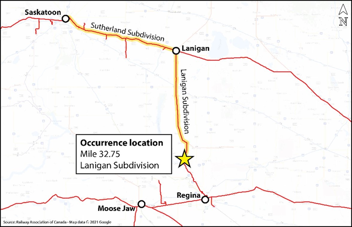
At about 2340, the train departed Sutherland Yard (Mile 109.7 of the Sutherland Subdivision) and travelled eastward to Lanigan, Saskatchewan (Mile 37.7 of the Sutherland Subdivision). At Lanigan, there is a junction where the train diverted southward onto the Lanigan Subdivision (Figure 2), toward Regina (Mile 0.0 of the Lanigan Subdivision). While en route on the Lanigan Subdivision, the train traversed 3 wayside hot bearing detectors (HBD)—at Mile 88.9, Mile 64.6, and Mile 37.1 respectively—with no alarms. There are no wheel impact load detectors on either the Sutherland or Lanigan subdivisions; however, an examination of previous wheel impact load detector records from other subdivisions did not show any abnormal wheel readings on any of the occurrence train’s locomotives and cars.
1.1 The occurrence
At 0502 on 16 October 2021, the train was proceeding southward at 38.6 mph when it experienced a train-initiated emergency brake application at Mile 31.58, near Silton, Saskatchewan. The head end of the train stopped at about Mile 31.18, after travelling approximately 2100 feet. Subsequently, the crew made the required emergency radio broadcasts and the conductor performed a walking inspection of the train. The conductor determined that 27 cars, located in the 125th to 151st positions behind the head-end locomotive, had derailed predominantly to the west side of the track. Many of the cars were breached and had released their contents (Figure 3). There were no injuries and no dangerous goods were involved. There was no danger to the public or the environment, although a significant amount of potash was released.
At the time of the occurrence, the temperature was −4 °C with light winds out of the northeast.
1.2 Site examination
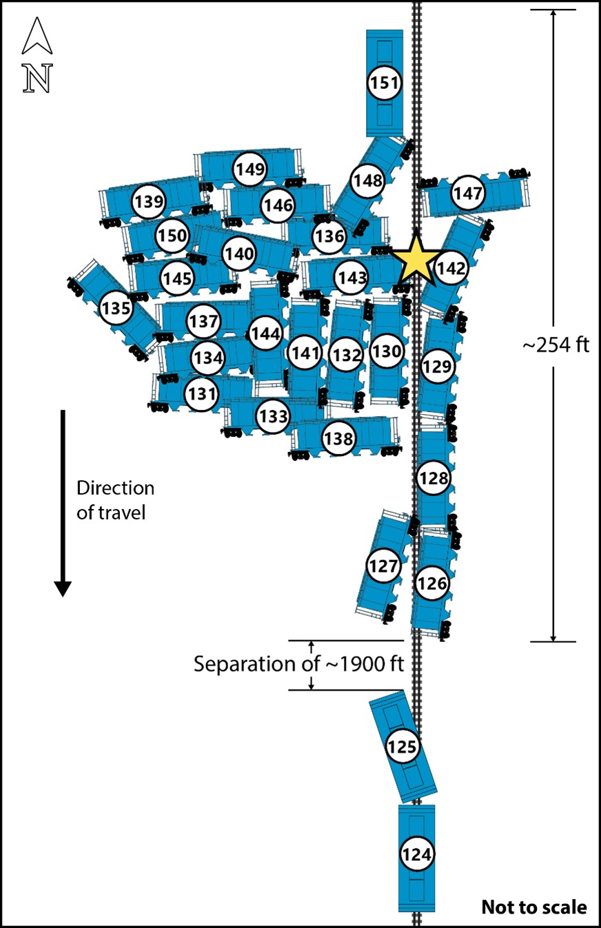
There were no visible wheel impact marks present on the track infrastructure leading up to the derailment location. However, significant track damage was observed extending southward up to the first derailed car (the 125th car, ITFX 33257). Only the trailing truck of that car was derailed to the west side of the track; the car remained coupled to the head end of the train as it was dragged for about 2100 feet. About 2100 feet of track was damaged or destroyed.
The next 25 derailed cars, the 126th to 150th cars from the head-end locomotive, came to rest clustered in a large pile, over a distance of 254 feet, near Mile 32.75 (Figure 4). The 151st car from the head-end locomotive was the last car to derail but remained upright.
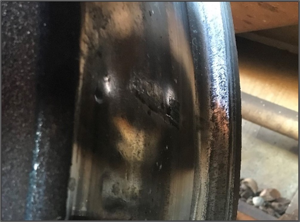
The last car of the head-end portion of the train that did not derail was the 124th car, CITX 151689. Inspection of this car revealed that the trailing R1 wheel tread (west side) displayed impact damage (Figure 5). At the occurrence temperature of −4 °C, a rail break would create a gap of 2 to 3 inches (51 to 76 mm) if the rail were properly stressed.Footnote 4 Such a gap would display extensive rail end batter from all the wheels in the head end of the train striking the gap. There was no impact damage to the wheels on any cars prior to the 124th car.
Following the TSB site inspection, the derailed rolling stock was pushed to the side and the track was reconstructed. The track reopened to train operations at 0300 on 17 October 2021. Site remediation and removal of the derailed rolling stock was completed on 27 October 2021.
1.3 Forward-facing locomotive video recorder
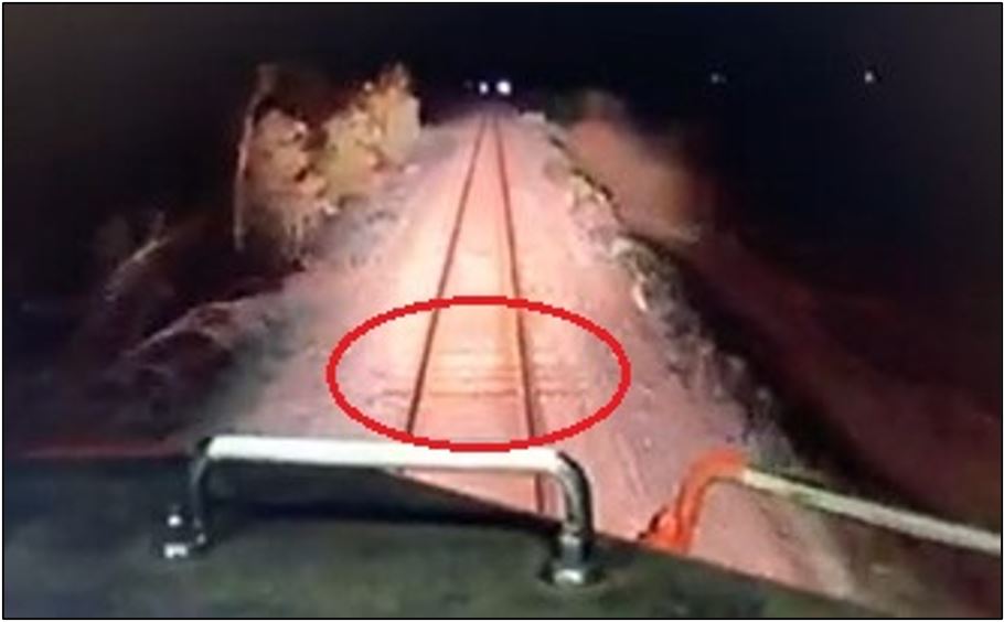
Although the head-end locomotive forward-facing video from train 603-897 did not show any anomalies on the rail surface, the external microphone did pick up a sound anomaly (noise) and the video showed that the locomotive dipped slightly to the right (Figure 6) as it traversed the suspected point of derailment in the vicinity of Mile 32.75. Neither the occurrence train crew nor the preceding crew reported any abnormalities while traversing that location.
1.4 Subdivision and track information
The CP Lanigan Subdivision is a single main track that extends from Regina (Mile 0.0) to Lanigan (Mile 104.4), where it intersects with the Sutherland Subdivision. Train movements are controlled by the occupancy control system (OCS) as authorized by the Canadian Rail Operating Rules (CROR) and are supervised by a rail traffic controller located in Calgary, Alberta. OCS territory is non-signalled (i.e., dark territory).
The track in the vicinity of the derailment was rated as Class 3, according to the Transport Canada–approved Rules Respecting Track Safety, also known as the Track Safety Rules (TSR). The authorized speed for freight trains at the location of the derailment was 40 mph and there were no slow orders in effect.
The track was mostly level and tangent and consisted of 115-pound continuous welded rail manufactured by Algoma Steel Inc. in 1977. The rail was set onto 14-inch double-shouldered tie plates secured with 3 spikes per plate. Rail was box-anchored every other tie using Improved Fair anchors.Footnote 5 The ties were a mix of moderate-condition hardwood, with 57 ties per 100 feet and approximately 7 defective ties per 100 feet. The ballast was 4.5 inches of crushed rock with a shoulder width of 1 foot. The cribs were full, and the ballast was in good condition.
Train traffic averages about 4 or 5 trains per day with an annual average tonnage of 19.36 million gross ton-miles per mile based on the 3-year average (i.e., from 2019 to 2021) (Table 1). The overall traffic tonnage was trending slightly downward over the same time period.
| Year | Subdivision | Miles | Gross ton-miles (GTM) | Annual tonnage | |
|---|---|---|---|---|---|
| Tons | Million gross ton-miles per mile | ||||
| 2019 | Lanigan | 104.4 | 2 044 299 917 | 19 581 416 | 19.58 |
| 2020 | Lanigan | 104.4 | 2 142 266 545 | 20 519 794 | 20.52 |
| 2021 | Lanigan | 104.4 | 1 877 025 224 | 17 979 169 | 17.98 |
1.5 Track inspection
The TSR set forth minimum regulatory requirements for track inspection. They require that Class 3 track with an annual tonnage between 15 and 35 million gross ton-miles per mile:
- receive a visual inspection (on foot or in a track vehicle) twice weekly,Footnote 6
- receive an electronic geometry car inspection by a heavy geometry inspection vehicle twice annually,Footnote 7,Footnote 8 and
- receive a rail flaw detection (RFD) inspection annually.Footnote 9
1.5.1 Visual inspection
The Lanigan Subdivision was visually inspected twice weekly. The most recent visual track inspections were performed by experienced CP track inspectors on 11 and 15 October 2021. There were no track geometry defects or rail surface defects noted in the vicinity of the derailment.
1.5.2 Geometry car inspection
The TSR require Class 3 track to have a minimum of 2 annual electronic geometry inspections conducted by a heavy geometry inspection vehicle. Additional inspections can also be conducted by light geometry and autonomous inspection vehicles.
A CP heavy track geometry inspection vehicle inspected the subdivision on 08 October 2021; no defects were reported between Mile 32 and Mile 33 during that inspection.
1.5.3 Rail flaw detection
The Lanigan Subdivision RFD testing frequency exceeded regulatory requirements. Both Canadian Class 1 railways recognize the value of frequent rail flaw testing, particularly during the colder winter months when fracture toughness is reduced and rail with pre-existing fatigue defects is more likely to fail.
Table 2 shows the defect rate per mile and testing frequency for the subdivision during the last 5 years preceding the occurrence.
| Year | Miles | Defects | Defect rate per mile | Yearly testing frequency |
|---|---|---|---|---|
| 2017 | 104.4 | 65 | 0.623 | 6 |
| 2018 | 104.4 | 72 | 0.690 | 6 |
| 2019 | 104.4 | 41 | 0.393 | 5 |
| 2020 | 104.4 | 41 | 0.393 | 9 |
| 2021 | 104.4 | 21 | 0.201 | 8 |
There were no rail defects identified in the area of the derailment when it was last tested by a Sperry Rail Service (Sperry)Footnote 10 RFD vehicle on 30 September 2021. The investigation has also confirmed that the RFD vehicle was operating properly on that date.
1.6 Track renewal programs
Between 2017 and 2021, CP undertook several track renewal programs for Class 3 track on some of its northern secondary main tracks, including the Lanigan Subdivision. The work was undertaken to maintain safe rail operations and to ensure that the track infrastructure remained in compliance with the TSR. The Lanigan Subdivision track renewal program was focused on rail replacement and surfacing, as well as tie replacement and gauging in the most problematic areas identified by geometry testing. Track surfacing was performed on 05 June 2020, between Mile 32.40 and Mile 33.20.
The last rail grinding operation in the area was completed on 30 August 2021. The primary purpose of rail grinding is to control rail surface fatigue defects by removing a thin surface layer of metal, which improves wheel–to–rail contact geometry, reduces contact stresses, and thus prevents the growth of micro cracks. It also increases the effectiveness of ultrasonic testing by providing a smoother rail surface.
1.7 Examination of recovered rail
Four rail samples, labelled Rail 1 to Rail 4, were recovered near the suspected point of derailment at Mile 32.75. The pieces, ranging from 2.3 to 5.6 feet (70 to 170 cm) long, were sent to the TSB Engineering Laboratory in Ottawa, Ontario, for examination.
Rail 1 did not contain any identification markings but was most likely manufactured in 1977, similar to the remaining rail installed in the area. It was 2.4 feet (73.2 cm) long and had a fracture surface at one end and a cut surface at the other.
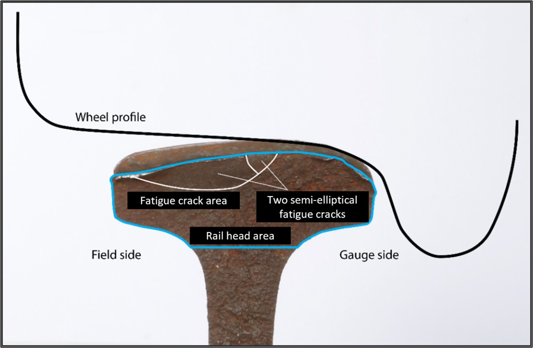
Examination of the fracture surface revealed 2 separate semi-elliptical flat and smooth fatigue cracks that grew over time due to repeated loading. The 2 cracks eventually merged and created a larger semi-elliptical crack that measured about 0.39 inch (10 mm) deep and covered 15% of the total area of the worn rail head. The remaining portion of the fracture surface was composed of coarser features with some faint chevrons, indicating that the fatigue crack propagated down to the base of the rail in a sudden overstress.
These types of fractures are categorized by Sperry as transverse/compound fractures. They initiate from rail surface conditions.Footnote 11 Once initiated, these cracks grow slowly to a size of 10% to 20% of the head area due to repeated loading from passing trains, and then they propagate suddenly.
The rail head running surface displayed a slight downward taper toward the field side. No similar taper was observed on the gauge side. The observed taper on the field side (Figure 7) suggests that this rail had been transposed, i.e., previously installed on the east side before being installed on the west side. According to CP track maintenance personnel, it was transposed during major rail work on the subdivision in 2007; however, there are no specific records indicating the origin of the rail.
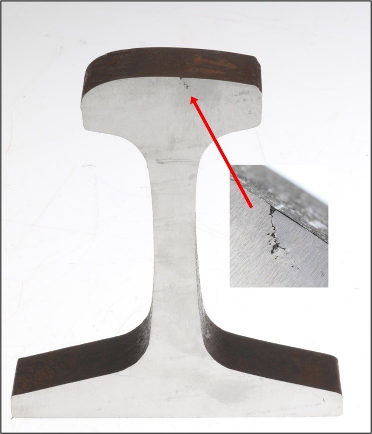
The top view of the rail running surface displayed minor head checks on the gauge side of the head and rail grinding marks on the field side of the head. There was impact damage, likely due to contact with freight car wheel treads, that extended across the rail head running surface, but there was no widening (horizontal expansion) of the rail head (Figure 8).
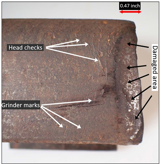
The damaged area of the Rail 1 fracture surface contained a depression that was located about 0.47 inch (12 mm) longitudinally from the fracture surface and gradually got deeper as it approached the fracture surface. The depression measured about 0.24 inch (6 mm) at its deepest point.
Subsequently, Rail 1 was cut vertically about 1.2 inches (30 mm) away from, and parallel to, the fracture surface. On the cut surface of the cross-section, a small vertical crack was observed extending from the rail running surface to a depth of about 0.24 inch (6 mm) (Figure 9).
Rails 2, 3, and 4 were fractured at each end of the rail. In each case, the fracture surfaces exhibited coarse granular features with some faint chevrons, consistent with a sudden overstress. There were no pre-existing defects observed on any of the fracture surfaces.
1.8 Rail wear
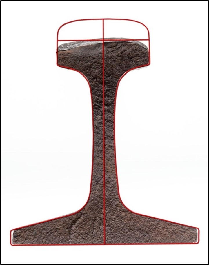
The measured vertical head wear for Rail 1 was 9/16 inch (14 mm) while the gauge face wear was minimal. According to the CP requirements, the maximum head wear permitted for 115-pound rail is 11/16 inch (16 mm). To illustrate the extent of the rail head wear, a new 115-pound rail cross-section was superimposed on the Rail 1 cross-section (Figure 10).
Vertical rail wear is known to increase the level of stress acting on the rail as well as the propagation of any rail defect that may be present, which can lead to rail failure. Following a VIA Rail Canada Inc. train derailment due to a broken rail near Matapédia, Quebec, on 12 March 2008,Footnote 12 a 3D finite element analysis (FEA) was undertaken to evaluate how vertical head wear influences the stresses on the rail head. FEA models were established for 4 different degrees of vertical head wear: 0 inch, 0.31 inch, 0.47 inch, and 0.63 inch (0 mm, 8 mm, 12 mm, and 16 mm). The models used simplified wheel load support points and bearing points. The stresses and loads in the models did not simulate exactly those that are applied to a rail in service. Nevertheless, these models are considered suitable for carrying out a comparative analysis and provide qualitative information on how vertical wear influences the stresses on the rail head.
The FEA findings show that high local stresses are associated with the bearing point of the loads applied by the wheels. Because the head is affected by vertical wear, the area of influence of these loads extends deeper in the rail head. The analysis identified a zone on the rail head where the stresses increased at a greater rate once vertical head wear exceeded a value of about 0.39 inch (10 mm). The stresses applied when wear reaches 0.63 inch (16 mm) are 3 to 4 times greater than the stresses applied when there is no wear.
1.9 Rail flaw detection technology
Railways rely on RFD testing to identify internal rail defects. RFD hi-rail vehicles are equipped with an undercarriage test platform that contains electromagnetic (induction) technology and ultrasonics to detect rail flaws. The ultrasonic testing equipment consists of 3 fluid-filled roller search unit wheels for each rail. Each roller search unit contains a number of transducers that generate high-frequency sound energy through the rail in the form of waves to detect vertical and transverse defects within the rail. A liquid couplant consisting of a thin film of water mixed with glycol or calcium facilitates the transmission of ultrasonic energy from the transducers into the rail.
Over the years, Sperry has developed and used RFD units that combine different transducer angles to achieve the best inspection possible. Fluid-filled wheels are used to house and couple the transducers to the rail.
At Sperry, there are 2 primary inspection units: a rail-bound vehicle that uses both ultrasonic and electromagnetic (induction) technologies to identify defects, and an ultrasonic-equipped hi-rail vehicle.
The data from the inspection equipment are fed to the operator inside the vehicle and visually presented on monitors. Six channels display the ultrasonic and induction signals and where exceptions occur relative to track features such as joints and crossings. Defect recognition software processes the inspection equipment’s raw data, and presents them on monitors. If an operator considers an indication to be suspect, the test vehicle is stopped, the operator gets out, and the rail is hand-tested. If a defect is confirmed, it is marked and a following crew changes the rail or otherwise protects it through slow orders.
RFD testing is a reliable and economical method of rail flaw testing. However, it has limitations, and a 100% accuracy rate is beyond current equipment capabilities. Furthermore, such testing is not an exact science: operator skill, training, and experience are all required to properly interpret data and identify defects. Moreover, operators are required to perform numerous tasks while testing, including monitoring test data as the data scroll by, and observing rail conditions and track features as the vehicle is travelling on the rails. Defects must be large enough and perpendicular or nearly perpendicular to the transducer axis for an equipment response to be processed and presented for operator interpretation.
Rail surfaces must also be smooth and clean to accept and properly reflect the transducer signal as the detectability of defects can be influenced by grease or dirt on the rail head. Surface conditions and even head wear can also affect the signal.
The track in the vicinity of the derailment was inspected before the accident by different Sperry inspectors.
1.10 American Railway Engineering and Maintenance-of-Way Association guideline
Since 100% accuracy in testing is not within the capabilities of current technology and equipment, the American Railway Engineering and Maintenance-of-Way Association (AREMA) established a recommended minimum performance guideline for RFD testing.Footnote 13 A reliability ratio is used to measure testing performance and is defined as the percentage of actual in-track defects that can be expected to be located in a single test by a test car that is operated by an experienced operator in service over a typical mix of track conditions. Reliability ratios depend on the size of defect and category of track. Table 3 shows the reliability ratio for transverse defects in the rail head for Category I track.Footnote 14
| Flaw size (percentage of head area) | Reliability ratio (percentage) |
|---|---|
| 5 to 10 | 65 |
| 11 to 20 | 85 |
| 21 to 40 | 90 |
| 41 to 80 | 98 |
| 81 to 100 | 99 |
The AREMA guideline can be used as the basis of an agreement between the rail testing operator and the railway for a minimum acceptable performance standard.
1.11 Broken rail detection
On subdivisions where train movements are governed by a signalled centralized traffic control system, wayside signals are installed along the railway right-of-way. The signals are connected by track circuits that operate through the rails. This system provides some protection against pre-existing broken joints and broken rails that result in rail gaps.
On subdivisions where train control movements are governed by the OCS, this protection is typically not provided. Consequently, broken joints and broken rails that result in a rail separation or rail gap may go undetected for a period of time unless identified through an inspection or observed by employees or crews on approaching trains. In response to derailments that occurred on CP subdivisions governed by OCS, in 2021, CP developed a broken rail detection system, the Rail Integrity Non-Vital Overlay Detectors (RINOD), for non-signalled territory. The RINOD system provides automatic notifications to CP’s Operations Centre in the event of a broken rail, rail gap, loose joint, or rail joint pull-apart, allowing the Operations Centre to stop a train before it encounters any such track discontinuities.
The RINOD system works by sending a low-voltage signal powered by solar cells and lithium-ion batteries through the rails and relies on technology such as miniaturized signal-processing circuits that transmit information to CP’s Operations Centre for continuous monitoring.
Although CP had installed the RINOD system on some of its non-signalled subdivisions prior to this occurrence, the system was not implemented on the Lanigan Subdivision at the time of the occurrence.
1.12 TSB laboratory reports
The TSB completed the following laboratory report in support of this investigation:
- LP029/2022 – Rail Examination
2.0 Analysis
Canadian Pacific Railway Company (CP) freight train 603-897 (the train), a unit train carrying potash, was operated in accordance with regulatory requirements. Neither the condition of the rolling stock nor the manner in which the train was operated is considered to be contributory to this accident. A broken rail sample containing defects was recovered from the derailment site. The analysis will therefore focus on the broken rail examination, rail wear and fatigue, rail flaw detection testing, and the detection of broken rails.
2.1 The accident
On 16 October 2021, the train was proceeding southward on the CP Lanigan Subdivision when the external microphone on the head-end locomotive picked up a noise and the forward-facing video showed the locomotive dipping slightly to the right in the vicinity of Mile 32.75. Shortly after, the train experienced a train-initiated emergency brake application and 27 cars, located in the 125th to 151st positions behind the head-end locomotive, derailed.
Examination of the trailing R1 (west side) wheel tread of the 124th car, which was the last car of the head-end portion of the train that did not derail, displayed impact damage that was consistent with the wheel tread having contacted an exposed rail head cross-section of the broken rail. At the occurrence temperature of −4 °C, a rail break would create a gap of 2 to 3 inches (51 to 76 mm) if the rail were properly stressed. Therefore, extensive rail end batter from wheels striking the gap would occur. The fact that the wheels of the preceding cars and locomotive did not exhibit any impact marks suggests that the rail was intact prior to the train’s arrival and that it broke under the 124th car.
Finding as to causes and contributing factors
CP potash unit train 603-897 derailed when the west rail broke, most likely under the trailing truck of the 124th car, in the vicinity of Mile 32.75 of the Lanigan Subdivision.
2.2 Broken rail examination
Four rail pieces, labelled Rail 1 to Rail 4, recovered from the west rail near Mile 32.75 were examined at the TSB Engineering Laboratory. There were no pre-existing defects observed on any of the fracture surfaces of rails 2, 3, and 4, indicating that the fractures were caused by overstress. However, the examination of the fracture surface of Rail 1 revealed 2 separate semi-elliptical fatigue cracks. Semi-elliptical fatigue cracks are features usually associated with pre-existing fatigue cracks that have grown in size over time due to repeated loading.
The 2 cracks eventually merged and created a larger semi-elliptical crack, the area of which represented about 15% of the total area of the worn rail head. The remaining portion of the fracture surface was composed of coarser features with some faint chevrons, indicating that the fatigue crack propagated down to the base of the rail in a sudden overstress as the occurrence train passed over it.
Finding as to causes and contributing factors
The west rail broke under normal service conditions when pre-existing fatigue cracks, representing about 15% of the total area of the rail head, propagated down to the base of the rail in a sudden overstress.
2.3 Rail wear and fatigue
The rail head wear permitted by CP for 115-pound rail is 11/16 inch (16 mm) and the measured vertical head wear for Rail 1 was 9/16 inch (14 mm). The rail head running surface was also slightly tapered towards the field side. The investigation determined that the rail had been transposed in 2007. Although the rail head wear was still within allowable limits, the amount of wear made it more susceptible to fatigue crack initiation and propagation. Furthermore, the presence of a small vertical fatigue crack extending from the rail running surface to a depth of about 0.24 inch (6 mm) in a section of Rail 1 located 1.2 inches (30 mm) away from, and parallel to, the fracture surface suggests that multiple cracks were probably present in this section of rail. Such cracking, which can propagate over time on a heavily worn rail head, such as the occurrence rail, could be indicative of rail approaching the limit of its service life.
Rail fatigue is influenced by many factors, with the accumulated traffic tonnage and associated stresses imparted on the rail playing a predominant role. Since the rail’s service origin and installation date are unknown, it is not possible to accurately determine the accumulated traffic tonnage that passed over the rail. However, the likely manufacture date (1977), measured rail wear, and presence of internal cracks suggest that Rail 1 was exposed to a high accumulated traffic tonnage over its service life.
A finite element analysis performed by the TSB following a VIA Rail Canada Inc. train derailment due to a broken rail near Matapédia, Quebec, on 12 March 2008,Footnote 15 showed that an increase in the vertical wear of the rail head results in an increase in the overall rail stresses from wheel loading, affecting the rail’s integrity and fatigue life.
Finding as to causes and contributing factors
Although the head wear of the rail that broke was within CP’s allowable service limits, the amount of head wear increased the level of stresses acting on the rail from wheel loading, which led to a reduced fatigue life of the rail and made it more susceptible to failure due to fatigue cracking.
2.3.1 Rail flaw detection testing
Rail flaw detection (RFD) testing is a reliable and economical method of identifying rail defects but has limitations. For instance, the American Railway Engineering and Maintenance-of-Way Association (AREMA) has acknowledged that 100% rail flaw detection accuracy during testing is not within the capabilities of current technology and equipment; consequently, AREMA has established a recommended minimum performance guideline for RFD testing.
The detectability of defects depends on the size and type of defect. According to the AREMA guideline, the reliability ratio for the size of the fatigue cracks observed on Rail 1 is 85%, meaning that, on average, up to 15% of rail defects may be undetected.
Finding as to risk
Given the limitations in accuracy of current RFD testing, rail with internal defects can sometimes be misclassified as free of defects, increasing the risk of failure and subsequent derailment.
The detectability of defects can also be negatively affected by rail surface conditions such as head checking, shelling, and spalling, and also by rail head wear. Transposed rail can also sometimes result in the RFD wheel sensor not making full contact with the rail head surface, affecting the effectiveness of RFD testing in these areas.
The track underwent RFD testing several times shortly before the accident by different Sperry Rail Service inspectors and no rail surface conditions were identified. In addition, the forward-facing video from the head-end locomotive did not display any visible anomalies in the track. However, the external microphone picked up a noise and the forward-facing video showed the locomotive dipping slightly to the right as it proceeded over the area in the vicinity of Mile 32.75, which likely was caused by a surface depression at the location of the fracture surface on the head of Rail 1.
Furthermore, the rail running surface of Rail 1 displayed minor head checks on the gauge side of the head, even though the last rail grinding operation in the area was completed on 30 August 2021.
Finding as to risk
Rail surface conditions may mask the presence of an emerging rail defect, increasing the risk that the defect will grow undetected, leading to a broken rail derailment.
In order to alleviate some of the risks associated with the limitation of RFD testing and the impacts of surface conditions on the detection of defects, railways have increased the frequency of RFD testing and rail grinding activities. Both Canadian Class 1 railways recognize the value of frequent rail flaw testing, particularly during the colder winter months when fracture toughness is reduced and rail with pre-existing fatigue defects is more likely to fail. For instance, the Lanigan Subdivision RFD testing frequency far exceeded regulatory requirements and grew eightfold in recent years.
The strategy adopted by CP has yielded substantial safety benefits and has led to a steady decline in the defect rate per mile on the Lanigan Subdivision since 2018; nevertheless, a review of the data from the last RFD testing performed before the derailment, on 30 September 2021, did not show any defects.
Finding as to causes and contributing factors
Despite regular RFD testing, which exceeded regulatory requirements, the accuracy limitations of current RFD testing equipment, combined with the transposed rail, rail head wear, and surface depression in the area of the rail fracture, most likely rendered the fatigue cracks difficult to detect.
2.4 Detection of broken rails
In non-signalled territory, such as the Lanigan Subdivision, there is no advance warning to protect train crews against track discontinuities such as broken joints and broken rails. Consequently, broken joints and broken rails that result in a rail separation or rail gap may go undetected for a period of time unless identified through an inspection or observed by employees or the crew of approaching trains.
In territory governed by the occupancy control system where CP’s Rail Integrity Non-Vital Overlay Detectors (RINOD) system is installed, automatic notifications are sent to CP’s Operations Centre in the event of a broken rail, rail gap, loose joint or rail joint pull-apart. The notifications provide advance warning that allow the Operations Centre to stop a train prior to it encountering any such track discontinuities in non-signalled territory. However, the RINOD system is unable to provide train crews with an advance warning of track discontinuities in all cases, such as when a rail breaks directly under a train.
Finding: Other
CP’s RINOD system is a substantial advancement in rail safety in territory governed by the occupancy control system.
3.0 Findings
3.1 Findings as to causes and contributing factors
These are conditions, acts or safety deficiencies that were found to have caused or contributed to this occurrence.
- Canadian Pacific Railway Company potash unit train 603-897 derailed when the west rail broke, most likely under the trailing truck of the 124th car, in the vicinity of Mile 32.75 of the Lanigan Subdivision.
- The west rail broke under normal service conditions when pre-existing fatigue cracks, representing about 15% of the total area of the rail head, propagated down to the base of the rail in a sudden overstress.
- Although the head wear of the rail that broke was within Canadian Pacific Railway Company’s allowable service limits, the amount of head wear increased the level of stresses acting on the rail from wheel loading, which led to a reduced fatigue life of the rail and made it more susceptible to failure due to fatigue cracking.
- Despite regular rail flaw detection (RFD) testing, which exceeded regulatory requirements, the accuracy limitations of current RFD testing equipment, combined with the transposed rail, rail head wear, and surface depression in the area of the rail fracture, most likely rendered the fatigue cracks difficult to detect.
3.2 Findings as to risk
These are conditions, unsafe acts or safety deficiencies that were found not to be a factor in this occurrence but could have adverse consequences in future occurrences.
- Given the limitations in accuracy of current rail flaw detection testing, rail with internal defects can sometimes be misclassified as free of defects, increasing the risk of failure and subsequent derailment.
- Rail surface conditions may mask the presence of an emerging rail defect, increasing the risk that the defect will grow undetected, leading to a broken rail derailment.
3.3 Other findings
These items could enhance safety, resolve an issue of controversy, or provide a data point for future safety studies.
- Canadian Pacific Railway Company’s Rail Integrity Non-Vital Overlay Detectors system is a substantial advancement in rail safety in territory governed by the occupancy control system.
4.0 Safety action
4.1 Safety action taken
4.1.1 Canadian Pacific Railway Company
On 29 July 2022, Canadian Pacific Railway Company (CP) implemented its Rail Integrity Non-Vital Overlay Detectors (RINOD) system on the Lanigan Subdivision. The RINOD system sends automatic notifications to CP’s Operations Centre in the event of a broken rail, rail gap, loose joint, or rail joint pull-apart. The notifications provide advance warnings that allow the Operations Centre to stop a train before it encounters any such track discontinuities in non-signalled territory.
This report concludes the Transportation Safety Board of Canada’s investigation into this occurrence. The Board authorized the release of this report on . It was officially released on .