Main-track train derailment
Canadian Pacific Railway Company
Freight train 516-398
Mile 48.86, Sutherland Subdivision
Near Guernsey, Saskatchewan
The Transportation Safety Board of Canada (TSB) investigated this occurrence for the purpose of advancing transportation safety. It is not the function of the Board to assign fault or determine civil or criminal liability. This report is not created for use in the context of legal, disciplinary or other proceedings. See Ownership and use of content. Masculine pronouns and position titles may be used to signify all genders to comply with the Canadian Transportation Accident Investigation and Safety Board Act (S.C. 1989, c. 3).
Summary
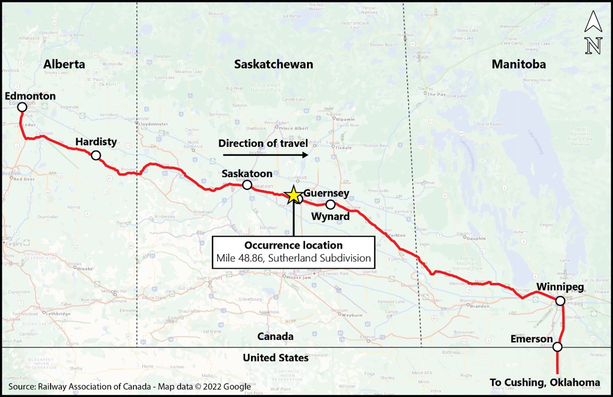
On 09 December 2019 at about 0010 Central Standard Time, Canadian Pacific Railway Company petroleum crude oil unit train 516-398 was proceeding eastward at 44 mph on the Sutherland Subdivision when a train-initiated emergency brake application occurred at the Wolverine Road public passive crossing located at Mile 48.85, near Guernsey, Saskatchewan. Subsequent inspection determined that 1 covered hopper car loaded with sand and 33 tank cars loaded with petroleum crude oil (UN1267, Class 3, Packing Group I) had derailed. Twenty of the 33 derailed tank cars were breached and released their contents. The released product ignited, and excess product gathered into a large pool that burned for about 24 hours. There were no injuries, and no evacuation was required.
It is estimated that a total of approximately 1.77 million litres of petroleum crude oil was released to the surface and atmosphere, which was about 57% of the total volume that was transported in the 33 derailed tank cars.
1.0 Factual information
On 08 December 2019, a Canadian Pacific Railway Company (CP) crew was ordered at 2015Footnote 1 in Saskatoon, Saskatchewan, to operate freight train 516-398, a unit trainFootnote 2 transporting petroleum crude oil (UN1267, Class 3, Packing Group [PG] I). The crew was to operate the train from Saskatoon to Wynyard, Saskatchewan, on CP’s Sutherland Subdivision. The train had been loaded at the Hardisty Terminal Footnote 3 in Alberta and was destined for Cushing, Oklahoma, United States, via Emerson, Manitoba. It was designated as a key trainFootnote 4 operating on a key route.Footnote 5
The train consisted of 1 head-end locomotive (CP 8946), 1 distributed power tail-end locomotive (BNSF 5100), and 101 cars. The first and the last cars were covered hopper cars loaded with sand; the other 99 cars were tank cars loaded with petroleum crude oil (crude oil). The train was 6130 feet long and weighed 14 217 tons.
The train crew consisted of a locomotive engineer and a conductor. Both crew members were qualified for their respective positions, met fitness and rest requirements, and were familiar with the territory on which they operated.
1.1 The accident
At about 0010 on 09 December 2019, the train was proceeding eastward at 44 mph on the Sutherland Subdivision. As the train approached the public passive crossing at Wolverine Road (Mile 48.85), located about 7 km west of Guernsey, Saskatchewan (Figure 1), the crew observed a gap in the south rail. As the head-end locomotive contacted the gap, it dipped to the south. Immediately afterward, a train-initiated emergency brake application occurred. The crew looked back and observed a large explosion as the head-end locomotive and first car separated from the train. Numerous tank cars on the head end of the train had derailed and were on fire.
The train came to a stop at 0011. Recognizing the danger associated with a crude oil fire, the crew moved the head-end locomotive and the first car to a safe location east of the accident site, then made the required emergency radio notifications. There were no injuries.
At the time of the accident, the temperature was −19 °C. In the 12 hours preceding the accident, the temperature averaged −19.3 °C.
1.2 Site examination
The derailment occurred at about Mile 48.86, which was just west of a public passive railway crossing at Wolverine Road (Mile 48.85) on the Sutherland Subdivision. The crossing was protected by standard reflectorized crossing signs. Wolverine Road is a 2-lane gravel road that crosses the rail line at approximately 90°. In the vicinity of the accident, the track runs parallel to Highway 16 (Yellowhead Highway), which is located about 100 m north of the rail line.
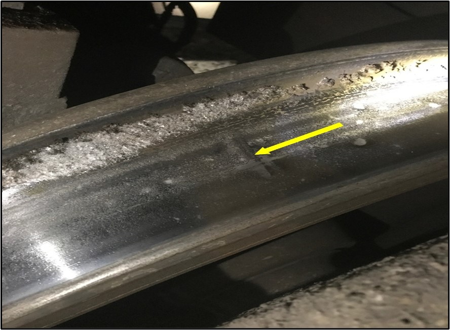
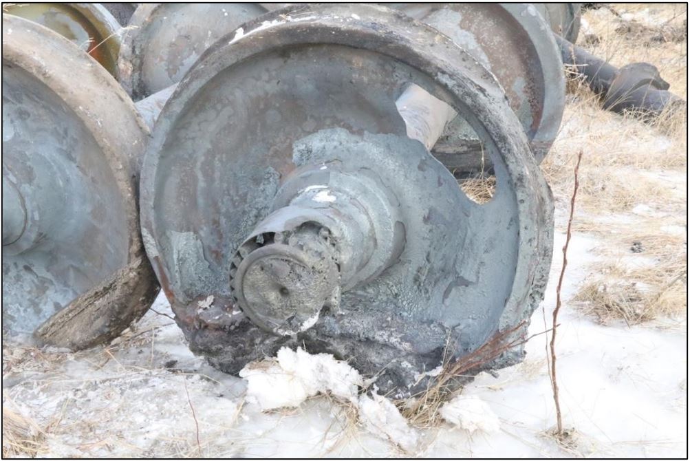
The first car in the train consist, a covered hopped car loaded with sand, had derailed but remained coupled to the head-end locomotive and traversed the crossing. All of the south wheels on the head-end locomotive exhibited transverse impact marks on the wheel treads (Figure 2).
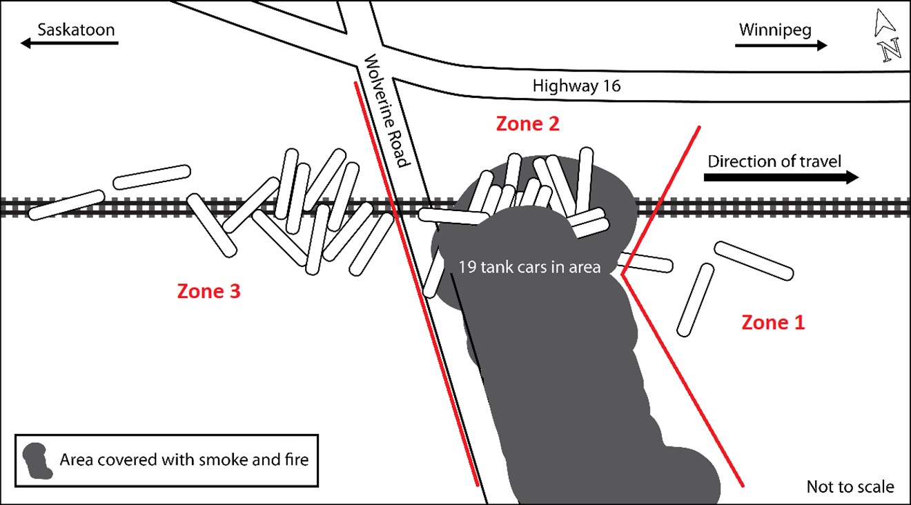
The 33 derailed tank cars (linesFootnote 6 2 to 34 inclusive in the train consist) were a mix of 9 DOT-117R and 24 jacketed Class 111 tank cars built to the CPC-1232 standard. During the derailment, the cars broke apart and came to rest in an east and west zone separated by Wolverine Road (Figure 3). A total of 20 of the 33 tank cars sustained breaches and released product.
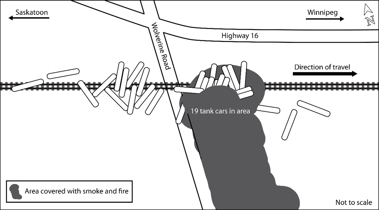
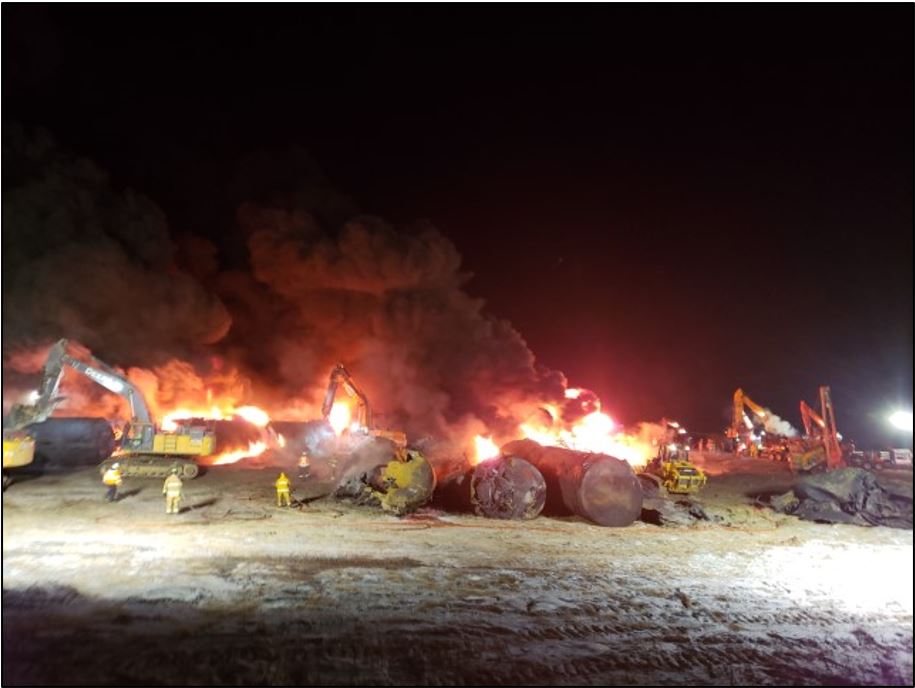
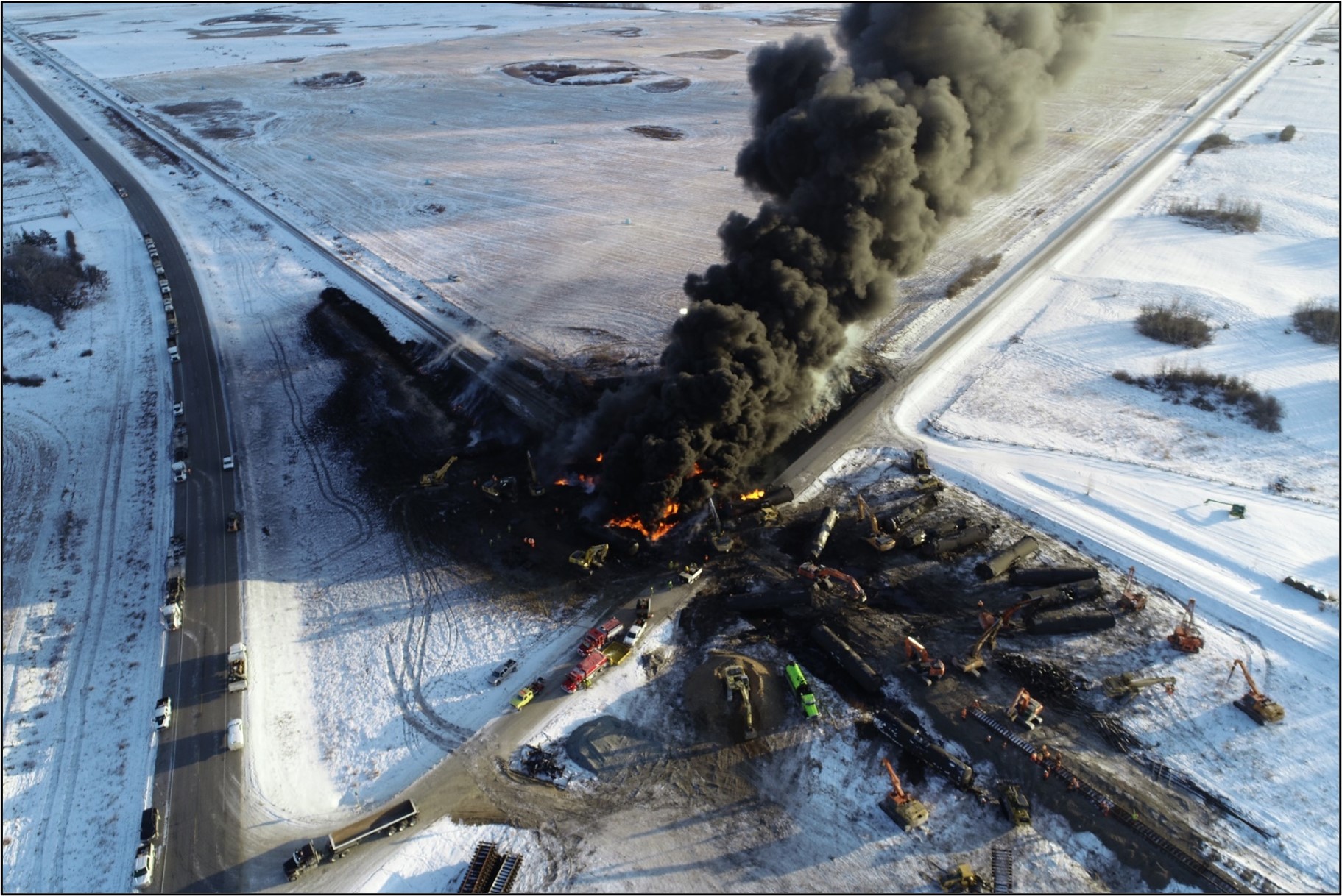
The first 21 tank cars (lines 2 to 22 inclusive) derailed east of the crossing and came to rest in various positions in a large pile-up over a short distance of about 500 feet. Most of these tank cars sustained breaches and released product. Due to the topography in the vicinity of the derailment, much of the released product flowed into a ditch created by the passive crossing, the highway, Wolverine Road, and the rail bed. The Wolverine Road embankment prevented the westward flow of the product, away from the main body of the derailment. This resulted in a significant portion of the released product settling under the derailed cars. The pooled product ignited and engulfed 19 of the tank cars in a large pool fire (Figure 4).
The fire burned for about 24 hours and resulted in the closure of Highway 16.
The remaining 12 tank cars derailed west of Wolverine Road. These cars remained relatively intact, with minimal damage and product release. However, during site mitigation activities, product flowed out of some cars and ignited. The remaining product from these cars was later transferred to other tank cars for shipment.
The track under the train was destroyed. All recovered rail pieces were examined on site, but rail from the suspected point of the derailment was not located.
1.3 Recorded information
The head-end locomotive was equipped with a locomotive event recorder (LER) and a forward-facing video camera.
1.3.1 Information from the locomotive event recorder
The relevant train handling events are shown in Table 1.
| Time | Train handling event |
|---|---|
| 0010:32 | The train was travelling at 44 mph. The throttle was in the idle position and the brake pipe pressure was 88 psi. |
| 0010:34 | The air brake pipe pressure dropped from 88 to 54 psi, indicating that a train-initiated emergency application of the train air brakes had occurred. Train speed dropped to 43 mph and the throttle remained in the idle position. |
| 0010:35 | The air brake pipe pressure dropped to zero and the train speed was 42 mph. |
| 0011:27 | The head-end locomotive came to a stop after travelling 0.395 mile after the emergency brake application had occurred. |
The LER data identified that a train-initiated emergency application of the train air brakes occurred just before the derailment. Prior to the emergency brake application, the train was handled in accordance with regulatory and company requirements.
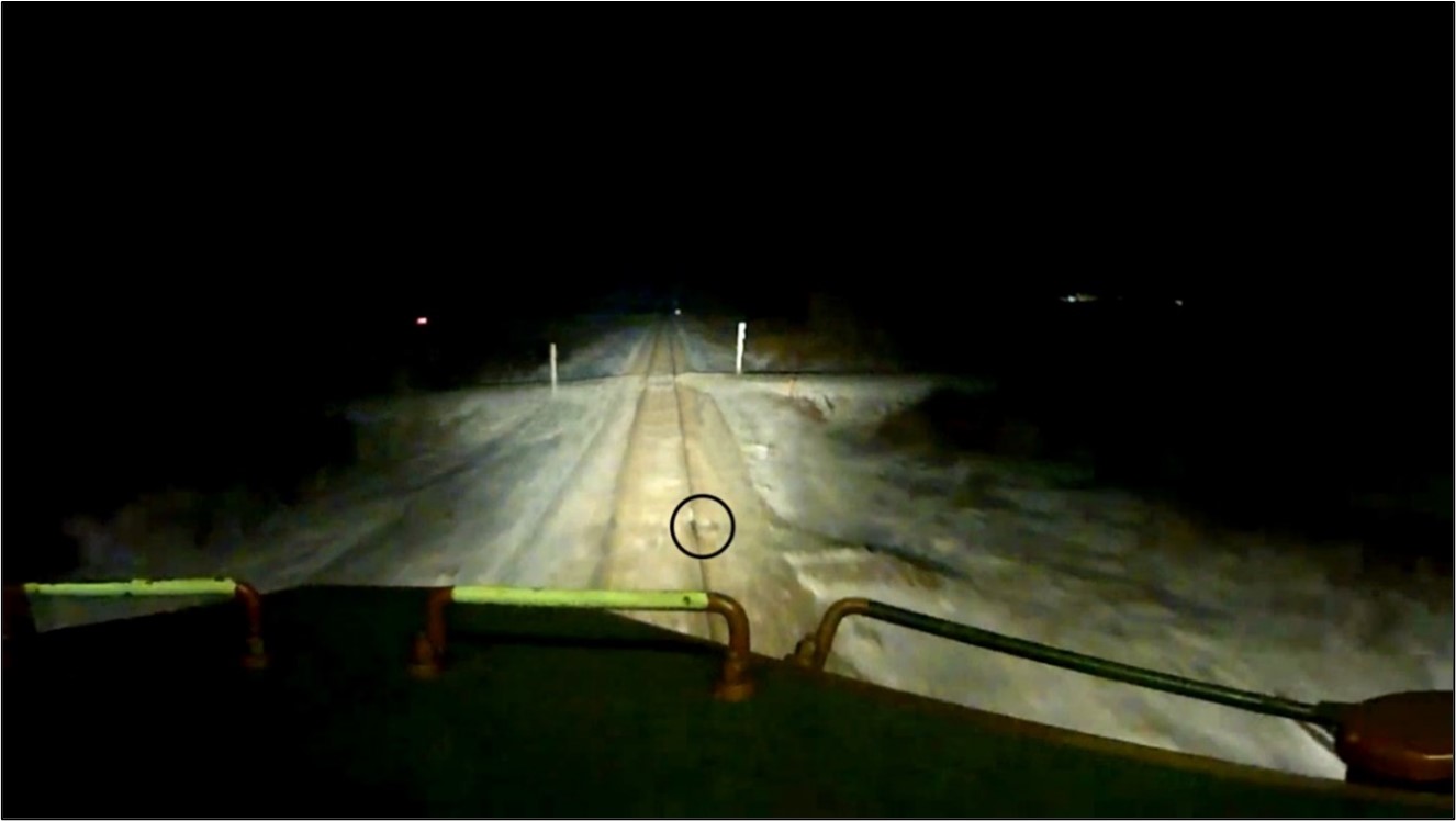
1.3.2 Information from the forward-facing video camera
A review of the video identified a gap in the south rail about 50 feet west of the Wolverine Road crossing (Figure 5).
It was determined that the rail had likely broken under the passage of a previous CP trainFootnote 7 prior to the arrival of the occurrence train. As the locomotive wheels went over the gap, there was a noticeable vibration of the recorded image.
1.4 Dangerous goods
The transportation of dangerous goods (DG)Footnote 8 is governed by federal legislation and regulations in CanadaFootnote 9 and in the United States.Footnote 10 In this occurrence, crude oil was being transported in each tank car. The product was listed as Class 3 flammable liquid, PG I, which is the most hazardous group in this class.
1.4.1 Class 3 flammable liquids
Class 3 flammable liquids are DG whose vapours can form an ignitable mixture with air at or below a temperature of 60 °C. These flammable liquids can pose serious hazards due to their volatility and flammability, which are determined by the initial boiling pointFootnote 11 and the flash point,Footnote 12 respectively.
Because the volatility and flammability of products within this class can vary widely, the products are grouped together based on these characteristics so that different requirements for packaging, storage, handling, and transportation can be established. According to the Transportation of Dangerous Goods Regulations, Class 3 flammable liquids are divided into 3 packing groups, ranging from PG I (highest hazard) to PG III (lowest hazard). The specific criteria for these packing groups are:
- PG I—if the flammable liquid has an initial boiling point of 35 °C or less at an absolute pressure of 101.3 kPa and any flash point;
- PG II—if the flammable liquid has an initial boiling point greater than 35 °C at an absolute pressure of 101.3 kPa and a flash point less than 23 °C; and
- PG III—if the criteria for inclusion in PG I or PG II are not met.
1.4.2 Petroleum crude oil
Crude oil is a Class 3 flammable liquid and on its own has a wide range of flammability and volatility. The product is usually qualified in terms of sulphur content (low sulphur being “sweet” and high sulphur being “sour”) and density (light to heavy). The density of crude oil is described in terms of its American Petroleum Institute (API) gravityFootnote 13 (expressed in degrees), where a higher number indicates lower density. The thresholds defining “light,” “medium,” and “heavy” crude oil vary depending on the product’s region of origin and the organization making the determination.Footnote 14
Crude oil can also vary in viscosity, which is often referred to as the thickness of a fluid. Products with low viscosity (e.g., water) flow freely, while products with high viscosity (e.g., molasses) are thicker and do not flow freely.
1.4.3 Emergency response procedures for petroleum crude oil
Guide 128 of the Emergency Response GuidebookFootnote 15 identifies the potential hazards of flammable liquids, including petroleum distillates and other crude oil products. Guidance is provided for emergency response and for ensuring public safety.
Under the heading “Potential Hazards,”Footnote 16 the guide indicates the following:
- These products are lighter than water, are highly flammable, and will be easily ignited by heat, sparks, or flames.
- The product vapours are heavier than air; they will spread along the ground and collect in low or confined areas (e.g., sewers, basements, or tanks). These vapours may form explosive mixtures with air and may travel to source of ignition and flash back.
- These products are associated with a vapour explosion hazard indoors, outdoors, or in sewers, and containers may explode when heated.
Under the headings “Emergency Response” Footnote 17 and “Public Safety,” Footnote 18 the guide indicates the following:
- Water spray, fog, or regular foam should be used to fight fire, but not straight streams of water. Because these products have a very low flash point, water spray may be inefficient; it may be necessary to use vapour-suppressing foam to reduce vapours.
- An initial downwind evacuation for at least 300 m (1000 feet) should be considered and all ignition sources must be eliminated.
- All equipment used when handling the product must be grounded.
- Responders must not touch or walk through spilled material.
- The leak should be stopped if it can be done without risk.
- Entry into waterways, sewers, basements, or confined areas should be prevented.
- Spilled product should be absorbed or covered with dry earth, sand, or other non-combustible material, and transferred to containers.
- Clean, non-sparking tools should be used to collect absorbed material.
1.5 Emergency response and site remediation activities
First on the scene were the Royal Canadian Mounted Police, the Lanigan fire department, and the Lanigan emergency medical services. CP responded with senior company officials, mechanical and engineering staff, hazardous material specialists, and its police services. Other responding agencies included Transport Canada (TC) and the Saskatchewan Ministry of the Environment. Multiple response contractors and environmental consultants were also mobilized and attended the site to support the emergency response and site mitigation.
ConocoPhillips Company Canada, the owner and shipper of the crude oil, implemented its emergency response plan, ERP2-1933-067. The plan sets forth the framework and procedures to safely and effectively respond to all types of emergencies, including those involving DG. It also serves as the Emergency Response Assistance Plan filed with TC under the Transportation of Dangerous Goods Act.
CP set up an on-site incident command centre and a unified incident command structure that included all responding agencies. The Lanigan fire chief assumed the role of incident commander. The derailment site was secured, and all access points were controlled. Due to the DG release, Wolverine Road and nearby Highway 16 were closed in the vicinity of the derailment. Roadways were re-opened to vehicular traffic at about 1500 on 12 December 2019. The immediate emergency response focused on firefighting efforts. During the first 12 hours, firefighting was defensive, attempting to maintain control of the pool fire (Figure 6).
The derailed tank cars were moved to clear the track, to orient the tank cars to minimize the release of product, to extinguish the fire, and/or to remove any remaining product from inside the cars. To accomplish this, tank car stub sills and/or top fitting protective housings were often used to move the cars, which sometimes resulted in additional tank car damage and breaches. This firefighting tactic also resulted in an accidental ignition of leaked product, which engulfed 11 derailed cars on the west side of Wolverine Road.
The embankment of Wolverine Road prevented the flow of the product away from the main body of the derailment in the westerly direction, but it also allowed the product to feed the fire for a longer period of time. Due to the extreme heat of the fires, the heavy equipment needed to be cooled repeatedly, which also added time to the fire-mitigation efforts. The fires burned for approximately 24 hours.
The air was continuously monitored to ensure the safety of personnel working at the site. Detectable levels of hydrogen sulphideFootnote 19 were observed where large amounts of oil were spilled and just inside the openings of tank cars (manways, valves, and tank breaches).
Berms were used to contain any crude oil on the ground that was not consumed in the fire. The oil in the berms was pumped into waiting trucks for environmental disposal. Any product remaining in the tank cars was transloaded into trucks, moved to a separate location, and then loaded into empty tank cars.
CP and its contractors performed site cleanup and remediation, which included removing all contaminated soil and ongoing environmental monitoring. No visible body of water in the vicinity of the derailment appeared to be affected.
The amount of released product was calculated based on the total known volume of crude oil in each of the 33 derailed tank cars and the total measured volume of product that was recovered during site remediation. It is estimated that a total of 1.77 million litres of crude oil was released to the surface and atmosphere. This represents a total of 60% of the total volume of product that was being transported in the 33 tank cars. While this is a reasonable estimate, the recovered product also included some effluent and water from firefighting activities, so the actual amount of crude oil that was lost may have been greater.
1.6 Subdivision information
The Sutherland Subdivision is a main track that extends westward from Wynyard (Mile 0.0) to Saskatoon (Mile 113.5). It is part of CP’s northern main line, which also includes the Hardisty, Wilkie, Wynyard, Bredenbury, Minnedosa, and Carberry subdivisions.
Train movements on the Sutherland Subdivision are governed by the occupancy control system (OCS), as authorized by the Canadian Rail Operating Rules and dispatched by a CP rail traffic controller located in Calgary, Alberta. Unlike subdivisions equipped with centralized traffic control (CTC), there are no wayside signals installed along the railway right-of-way to govern train movements in OCS territory.
1.6.1 Traffic volumes
Freight traffic volumes on the Sutherland Subdivision had been trending upward in the 5 years preceding the occurrence. Similarly, the volume of crude oil transported over the subdivision trended upwards in 2017, 2018, and 2019 (Table 2). The majority of crude oil was shipped by CP crude oil unit trains.
| Year | Freight traffic volume (million gross ton-miles per mile) | Car loads of crude oil | Crude oil volume (litres) |
|---|---|---|---|
| 2015 | 16.2 | 11 039 | 1 214 290 000 |
| 2016 | 12.8 | 1 936 | 212 960 000 |
| 2017 | 16.0 | 10 523 | 1 157 530 000 |
| 2018 | 22.5 | 49 711 | 5 468 210 000 |
| 2019 | 26.1 | 77 312 | 8 504 320 000 |
1.7 Track information
The track on the Sutherland Subdivision is a Class 4 track under the Rules Respecting Track Safety, otherwise known as the Track Safety Rules (TSR).
Rail on the Sutherland Subdivision was predominantly older rail manufactured by either Sydney Steel Corporation or Algoma Steel Inc. in the 1960s, 1970s, and 1980s.
In the vicinity of the derailment, the single main track was tangent and was oriented in a northwest/southeast direction. The track was relatively flat, with a slight descending grade in the southeast direction. The authorized speed for eastbound freight trains through the area is 45 mph. At the time of the occurrence, there were no slow orders in effect.
The track consisted of 115-pound continuous welded rail (CWR) manufactured by Algoma Steel Inc. in 1966. The rail had been previously used at another location and usable rail was re-laid and installed on the Sutherland Subdivision in 1985. The rail had several joints, bolted with 115-pound joint bars with 6 bolts per joint. It rested on hardwood ties, secured on 14-inch double-shouldered tie plates and fastened with 3 spikes per plate (1 spike on the field side and 2 spikes on the gauge side).
There were 57 ties per 100-foot section of rail. In the vicinity of the derailment, approximately 25% of the ties were defective.
The ballast in the area of the derailment was pit run rock, consisting mainly of small, rounded stones (up to 4-inch-diameter); in areas where the ballast had been upgraded, 4.5-inch crushed rock ballast was used. The ballast had a 2-to-1 slope for drainage on either side of the track bed.
1.8 Track inspection
The TSR set forth the minimum regulatory requirements for track maintenance and inspection and require that Class 4 CWR track with an annual tonnage of between 15 and 35 million gross tons:
- receive a visual inspection (on foot or in a track vehicle) twice weekly, Footnote 20
- receive an electronic geometry car inspection by a heavy geometry inspection vehicle twice annually, Footnote 21, Footnote 22 and
- receive a rail flaw detection (RFD) inspection 3 times annually. Footnote 23
CP inspections of the Sutherland Subdivision met or exceeded the regulatory requirements as outlined below.
1.8.1 Visual inspection
The TSR in effect at the time of the accident had no interval requirement for specific joint bar inspections. Joint bars were one of the track components examined during regular visual track inspections.
During CP’s regular twice-weekly track inspections between 06 September and 08 December 2019, a number of broken joints and 2 broken rails that resulted in rail gaps were identified (Table 3):
| Date (2019) | Mileage | Rail gap* (inches) | Broken rails |
|---|---|---|---|
| 06 September | 99.6 | 0.75 | 0 |
| 30 September | 37.2 | Unknown | 0 |
| 30 September | 62.1 | 1.25 | 0 |
| 02 October | 53.1 | 1.25 | 0 |
| 03 October | 47.2 | 1.25 | 0 |
| 03 October | 82.93 | Unknown | 0 |
| 09 November | 62.6 | Unknown | 1 |
| 14 November | 85.2 | 2.63 | 0 |
| 29 November | 61.8 | 2.00 | 0 |
| 09 November | 62.6 | Unknown | 1 |
| 06 December | 101.3 | 1.75 | 0 |
| 08 December | 51.9 | Unknown | 0 |
| 08 December | 59.1 | Unknown | 0 |
* The length of a rail gap is indicative of the tensile force acting on the CWR.
The last CP visual track inspection conducted before the derailment was on 08 December 2019. It identified 2 rail gaps west of the derailment area at Mile 51.9 and at Mile 59.1, respectively. CP repaired all rail gaps as they were identified.
1.8.2 Geometry inspection
CP’s heavy track geometry vehicle tested the Sutherland Subdivision in March, August, and November 2019 (Table 4), which exceeded the TSR minimum requirements.
| Month | Mileage tested | Urgent defects* | Near urgent defects** |
|---|---|---|---|
| March | Mile 0.0 to Mile 1.0 | 7 | 7 |
| Mile 0.0 to Mile 38.0*** | 3 | 7 | |
| Mile 38.0 to Mile 113.5 | 57 | 109 | |
| August | Mile 0.0 to Mile 38.0 | 24 | 5 |
| Mile 38.0 to Mile 108.0 | 107 | 45 | |
| Mile 108.0 to Mile 113.0 | 10 | 12 | |
| November | Mile 4.0 to Mile 44.0 | 0 | 0 |
| Mile 44.0 to Mile 100.0 | 12 | 0 | |
| Mile 108.0 to Mile 112.0 | 0 | 0 | |
| Total | 220 | 185 |
* Urgent defects require a mandatory slow order (unless corrected before the passage of a train) and include all CP and regulatory violations.
** Near urgent defects must be inspected and corrected as soon as possible. If necessary, they must be protected by a slow order until remedied.
*** This inspection overlapped the inspection from Mile 0.0 to Mile 1.0.
The increasing frequency of urgent track defects detected on a subdivision is indicative of the overall condition of the track on a subdivision. A higher number of urgent track defects suggests that the overall condition of a track requires increased maintenance.
Of the 220 urgent defects detected on the Sutherland Subdivision in 2019, the most common defects identified were for narrow gauge (117), design elevation related to cross-level (56), and other surface conditions (24).
When the gauge of the track is less than the nominal designed standard (4 feet and 8 ½ inches), the gauge is considered narrow or tight. On tangent track, narrow gauge promotes an unstable ride for rolling stock, which contributes to truck hunting as well as accelerated wheel and rail wear. Narrow gauge conditions can be indicative of the deterioration of the track structure related to tie conditions because it is no longer able to maintain track gauge under dynamic conditions.
1.8.3 Rail flaw detection inspection
Railways generally increase the frequency of RFD inspections to monitor track conditions when there is increased tonnage, or there are indications that the condition of the rail on a subdivision may require additional maintenance. Although the Sutherland Subdivision only required 3 RFD inspections per year, in 2019, CP conducted 7 RFD inspections (Table 5).
| Month | Weld defects* | Bolt hole defects | Head/web defects | Total |
|---|---|---|---|---|
| February | 8 | 4 | 5 | 17 |
| March | 3 | 2 | 2 | 7 |
| May | 8 | 3 | 3 | 14 |
| June | 5 | 2 | 1 | 8 |
| August | 7 | 2 | 1 | 10 |
| September | 4 | 3 | 8 | 15 |
| November | 9 | 6 | 1 | 16 |
Total |
44 | 22 | 21 | 87 |
* Weld defects include defects affecting plant welds, which are installed when the CWR is manufactured; flash butt welds; and thermite welds, which are usually welded in place in the field (and thus are also known as field welds).
The RFD inspections identified a total of 87 defects that required repair by cutting out the rail (where the defect was located) and installing a plug rail.
1.9 Additional Canadian Pacific inspections
To supplement track geometry inspections, CP uses some locomotives to conduct vehicle track interaction (VTI) inspections. VTI locomotives are equipped with accelerometers that allow them to monitor track conditions and communicate “rough spots” in the track while in normal train operation. The rough spots potentially identify higher than usual wheel impact locations or excessive locomotive body movement due to a track condition, each of which could lead to a potential broken rail. In 2019, there were no VTI events that required immediate attention in the area of the derailment.
At the time of the occurrence, CP also had 2 autonomous track geometry measuring systems (ATGMS). ATGMS is a specially equipped box car that operates in revenue train service and provides more frequent geometry testing. This enables more effective trending of track condition and identifies geometry conditions more proactively as they start to emerge. The ATGMS supplements the 2 CP manned track evaluation cars currently in operation. In 2019, there were no ATGMS events that required immediate attention in the area of the derailment.
1.9.1 Walking joint bar inspections
CP requires Class 4 CWR track with an annual tonnage between 15 and 35 million gross tons to receive a joint bar inspection twice annually. These walking joint bar inspections are specifically looking for cracked/broken joint bars as well as loose, broken, or missing bolts.
In the vicinity of the accident, CP conducted joint bar inspections as required, on 24 June 2019 (Mile 45.0 to Mile 50.0) and 06 December 2019 (Mile 37.0 to Mile 50.0) respectively, and no joint bar defects were found.
1.10 Regulatory oversight of the track infrastructure
TC monitors the railway infrastructure through its track inspection program. The program monitors the rail companies’ compliance with applicable rules and regulations on federally regulated rail lines and identifies any potential threats to safety. Track inspections by TC include reviewing rail inspection records and on-site inspection of track infrastructure.
In the 5 years preceding this occurrence, TC conducted several regulatory inspections of the Sutherland Subdivision:
- In 2016, TC inspected 7 miles of track immediately east of Sutherland Yard (Mile 108.7).
- In August 2018, TC inspected the track from Mile 102.0 to Mile 109.7 (7.7 miles). Subsequently, TC issued CP a Letter Of Non-Compliance And Concern in which TC identified 79 non-compliant tie conditions that required immediate attention. The 79 non-compliant tie conditions had been previously identified by a CP track inspector but had not been protected or addressed. To protect against the defective tie conditions, CP immediately reduced the class of track at those locations from Class 4 (45 mph speed limit) to Class 2 (25 mph speed limit). Once CP made the appropriate track repairs, the speed restriction was lifted.
- In 2019, TC inspected about 166 miles of track at various locations and noted defects that did not meet the TSR minimum requirements (Table 6).
| Date | Mileage inspected | Number of miles inspected | Narrow gauge defects | Locations with defective ties |
|---|---|---|---|---|
| 06 May | Mile 97.81 to Mile 107.00 | 9.19 | 3 | 0 |
| 07 May | Mile 38.37 to Mile 67.03 | 28.66 | 25 | 2 |
| Mile 71.03 to Mile 97.82 | 26.79 | 0 | 1 | |
| 27 August | Mile 38.37 to Mile 46.75 | 8.38 | 0 | 0 |
| Mile 46.86 to Mile 70.05 | 23.19* | 0 | 0 | |
| Mile 70.04 to Mile 107.24 | 37.20 | 0 | 0 | |
| 30 August | Mile 0.71 to Mile 38.40 | 37.69 | 0 | 0 |
| Totals | 171.28 | 28 | 3 |
* Transport Canada’s track inspection report stated 23.37 miles.
The inspections revealed narrow gauge and tie condition defects that required immediate attention. The defects identified by TC were subsequently corrected by CP at the identified locations.
The same TC inspections also revealed locations that exhibited track conditions that were approaching the TSR minimum requirements (Table 7).
| Date | Joint condition | Locations with track gauge condition near TSR minimum | Locations with suspect tie conditions | Surface conditions | Total |
|---|---|---|---|---|---|
| 06 May | 0 | 0 | 0 | 2 | 2 |
| 07 May | 0 | 81 | 1 | 14 | 96 |
| 0 | 0 | 1 | 50 | 51 | |
| 27 August | 3 | 16 | 0 | 6 | 25 |
| 0 | 29 | 1 | 4 | 34 | |
| 3 | 3 | 2 | 2 | 10 | |
| 30 August | 0 | 0 | 0 | 5 | 5 |
| Total | 6 | 129 | 5 | 83 | 223 |
The track defects and conditions identified by TC indicated that the track infrastructure on the Sutherland Subdivision required additional maintenance.
1.11 Regulatory requirements for risk assessments
The Railway Safety Management System Regulations, 2015 (SMS Regulations) and the 2016 Rules Respecting Key Trains and Key Routes (KTR) both require railway companies to conduct regular risk assessments of their operations.
Section 15 of the SMS Regulations states, in part:
A railway company must conduct a risk assessment in the following circumstances:
[…]
(c) when a proposed change to its railway operations, including a change set out below, may affect the safety of the public or personnel or the protection of property or the environment:
[…]
(iii) an increase in the volume of dangerous goods it transports,
[…] Footnote 24
Section 6.1 of the KTR states, in part:
Companies shall conduct risk assessments and periodic updates based on significant change to determine the level of risk associated with each Key Route over which Key Trains are operated by the company. These Key Route Risk Assessments must be conducted for all Key Routes, at a minimum, every three (3) years […]Footnote 25
1.11.1 Canadian Pacific risk assessments for the Sutherland Subdivision
In accordance with the KTR, CP conducted Key Route Risk Assessments for the Sutherland Subdivision in 2014 and 2017. CP identified and defined 28 factors prescribed in the KTR when it assessed the safety- and security-related risks associated with each key route. Among other factors, these risk assessments considered:
- rail traffic density, including volumes of DG being transported,
- various rail infrastructure,
- track grade and curvature,
- presence or absence of wayside detector systems,
- speed of operations, and
- presence or absence of signal control systems.
The risk assessments also identified additional technologies that are being implemented by CP to supplement existing inspections and other activities in an effort to reduce risk. However, the assessments did not consider the frequency of identified defects (track geometry or RFD) that required immediate attention for each of the corridor risk assessment subdivisions.
The 2017 assessment indicated that ballast and tie replacement programs were planned for 2020 for the section of track between Mile 37.0 and Mile 113.5, which included the area where the derailment occurred (Mile 48.86). No other track renewal programs were identified.
Despite increases in crude oil DG traffic on the subdivision, there were no additional risk assessments conducted in either 2018 or 2019.
1.12 Use of joints in continuous welded rail
Rail joints are a common track feature, even in CWR, and may be necessary at track appurtenances such as switches and turnouts and where defective sections of rail have been cut out and replaced with plug rails. It is well known that a lack of stability in a rail joint creates favourable conditions for fatigue cracking in the joint bars,Footnote 26 which can lead to joint failures that result in rail gaps and derailments.
Once assembled, a rail joint must preserve the continuity of the rail by providing about the same strength, stiffness, flexibility, and uniformity as the rail itself. Properly supporting the joint with sound ties and tamped ballast is necessary to accomplish this. However, the moment of inertia of properly installed joint barsFootnote 27 is still only about 1/3 of the moment of inertia (I-value) for corresponding non-jointed rail.Footnote 28 Consequently, even when the joint bars are attached tightly to a rail, the resulting joint is still a weak spot in the track structure.
In new CWR, joints are usually only installed to accommodate some track appurtenances (switches, turnouts, etc.). As CWR wears, RFD testing identifies rail defects that need to be cut out of the CWR and repaired with a plug rail that is secured in the track by a rail joint at either end of the plug. This may introduce additional joints to the rail for every plug rail repair. An increasing number of plug rails and joints in CWR territory is indicative of a rail condition or track structure that requires additional maintenance.
CP recognized the need to reduce the number of plug rails and joints on the Sutherland Subdivision. From 2017 to 2019, track maintenance crews were expanded to focus on joint elimination. As of 09 December 2019, about 700 joints remained on the subdivision.
1.13 Track renewal programs
Track renewal programs aim to strengthen the track structure to reduce the risks of derailment and may include:
- rail relay (replacing rail that is close to its wear life and/or fatigue life);
- tie renewal (replacing defective ties);
- joint elimination (removing rail joint bars and welding the rail ends together);
- ballast undercutting (replacing fouled ballast with clean ballast);
- track surfacing (using maintenance-of-way equipment to maintain the track structure to the required geometry specifications); and
- turnout replacement.
Between 2015 and 2019, CP undertook several track renewal programs for Class 4 track on its northern main line corridor, which includes the Sutherland Subdivision. The work was undertaken to remain in compliance with the TSR, and not necessarily in anticipation of any increase in crude oil volume transported.
The work on the Sutherland Subdivision was focused on joint elimination in CWR territory. Ties were replaced in the most problematic areas and a full tie replacement program was planned for 2020. In the area of the accident, track surfacing was performed from Mile 48.10 to Mile 50.0. A summary of the track work performed on the Sutherland Subdivision from 2015 to 2019 is outlined below (Table 8).
| Year | New rail installed (feet) | Number of ties replaced | Track surfacing (feet) | Rail destressing (locations) | Track gauging (feet) | Joints eliminated |
|---|---|---|---|---|---|---|
| 2015 | 0 | 0 | 136 303 | 0 | 0 | 56 |
| 2016 | 17 717 | 0 | 129 393 | 0 | 0 | 396 |
| 2017 | 0 | 2 656 | 315 883 | 0 | 44 746 | 524 |
| 2018 | 2 952 | 2 203 | 316 883 | 0 | 103 316 | 384 |
| 2019 | 12 824 | 53 673 | 115 384 | 26 | 51 572 | 200 |
1.14 Longitudinal stresses on continuous welded rail
CWR is fixed along its length, which limits its freedom of expansion and contraction. This type of rail, therefore, can experience great longitudinal compressive and tensile stresses from the forces exerted by passing trains and from ambient temperature changes. Rail expands when heated and contracts when cooled, which subjects the rails to thermal longitudinal stresses.
As temperatures elevate in CWR territory, rails tend to expand, which introduces longitudinal compressive forces that can result in track buckles. In contrast, as temperatures cool, the rail is subjected to longitudinal tensile forces that, if not managed properly, can lead to rail joint failures and/or broken rail resulting in rail gaps.
To withstand longitudinal stresses in CWR territory, the rail must be properly supported and secured and its neutral temperature must be properly managed. Footnote 29 Restraining the rail in the track is dependent upon having sound ties, sufficient anchors, and clean crushed rock ballast.
Rail anchors transmit the longitudinal forces to the ties. The ties, embedded in the ballast, absorb the forces, which are then transferred to the subgrade. If one or more of the track components is not contributing to the expected resistance, the potential for track irregularities increases. For instance, if anchors are not applied to sound ties, they will not provide the expected restraint. Similarly, on pit run ballast that consists of small, rounded stones with relatively few fracture faces, ties may not embed and therefore also not provide the expected restraint.
1.15 Detection of broken joints and broken rails that result in rail gaps
On subdivisions where train movements are governed by a signalled CTC system, wayside signals are installed along the railway right-of-way to govern train movements. The signals are connected by track circuits that operate through the rails. In CTC territory, a small electrical current passes through the rails to provide electrical continuity of a track circuit, which in turn activates the wayside signal system. This system provides some protection against broken joints and broken rails that result in rail gaps.
A broken joint or rail in CTC territory will often interrupt the track circuit, which causes the signals that govern the movements to “fail safe” and display the most restrictive indication, usually a red (stop) signal. If this occurs, a train must come to a stop or receive permission to pass a stop signal from a rail traffic controller and then proceed through the block at restricted speed (15 mph) while being on the lookout for broken rails.
In OCS territory, such as the Sutherland Subdivision, there is no such protection. Consequently, broken joints and broken rails that result in rail gaps can go undetected unless observed by the crew of an approaching train, by which time it is often too late to stop the train before it traverses the area.
There is technology available to help in the detection of broken rails in non-signalled territory. In the United States, the BNSF Railway Company has installed and tested different systems beginning in 2010.Footnote 30 However, at the time of this occurrence, the use of this technology was not widespread.
1.16 TSB safety issues investigation
In response to a series of train derailments on secondary main lines involving broken rails in the winter of 2003–2004, the TSB conducted a safety issues investigation.Footnote 31 The study established a significant relationship between rail defects and the level of bulk unit train traffic on secondary main lines and found that the effect of increasing bulk train traffic had not been accommodated through regular maintenance. The same circumstances could also apply to some main line track. The study also identified the following:
- Where rail weight is less than 130 pounds, increased bulk unit train tonnage significantly increases rail defects, resulting in a higher risk of broken rail derailments.
- Railways recognized that the rate of track degradation was accelerated with increases in bulk unit train tonnage on secondary main lines. However, an appropriate balance between increased track degradation and timely infrastructure maintenance and/or renewal had not been achieved.
- Compliance with the TSR in and of itself may be insufficient to ensure safety since the TSR did not provide a means to anticipate changing conditions such as increased traffic over the long term.
1.17 Derailments involving tank car unit trains transporting crude oil
From 2013 to 2019, the TSB has investigated 4 other serious derailments involving tank car unit trains transporting crude oil. As a result of these 4 derailments, a total of 168 tank cars loaded with crude oil derailed, releasing a combined total of 11.64 million litres of product.
1.17.1 Lac-Mégantic accident and recommendation related to tank cars
On 05 July 2013, at about 2250 Eastern Daylight Time, Montreal, Maine & Atlantic Railway (MMA) freight train MMA-002, en route from Montréal, Quebec, to Saint John, New Brunswick, was stopped at Nantes, Quebec (Mile 7.40 of the Sherbrooke Subdivision), the designated MMA crew-change point. The train, consisting of 5 head-end locomotives, 1 VB car (i.e., special-purpose caboose), 1 box car, and 72 Class 111 tank cars carrying crude oil, was then secured on the main track and left unattended on a descending grade.
Shortly before 0100 on 06 July 2013, the unattended train started to move, and gathered speed as it rolled, uncontrolled, down the descending grade toward the town of Lac-Mégantic, Quebec. After reaching a speed of 65 mph, 63 Class 111 unjacketed tank cars and the box car derailed near the centre of the town. The derailed cars released approximately 5.98 million litres of product due to tank car damage. The released product ignited almost immediately, resulting in a large pool fire that burned for more than a day. A total of 47 people were fatally injured. Many buildings, vehicles, and the railway tracks were destroyed. About 2000 people were initially evacuated from the surrounding area.
As part of the Lac-Mégantic investigation,Footnote 32 the Board highlighted the vulnerabilities of Class 111 tank cars and recommended that
the Department of Transport and the Pipeline and Hazardous Materials Safety Administration require that all Class 111 tank cars used to transport flammable liquids meet enhanced protection standards that significantly reduce the risk of product loss when these cars are involved in accidents.
TSB Recommendation R14-01
1.17.1.1 TSB assessment of Transport Canada’s response to Recommendation R14-01 (March 2023)
As part of its mandate, the TSB makes recommendations to eliminate or reduce safety deficiencies that pose significant risks to the transportation system and warrant the attention of regulators and industry. The Board assesses responses to recommendations according to the extent to which the safety deficiency has been or is being addressed. Once recommendations have been assessed as Fully Satisfactory, they are closed.
Since issuing TSB Recommendation R14-01, which called for enhanced protection standards for Class 111 tank cars, the Board monitored and assessed the industry’s and the regulators’ responses on a yearly basis.
In 2015, North American regulators and the railway industry developed and implemented a new tank car standard, the TC/DOT 117J, as well as retrofit requirements for older Class 111 tank cars in flammable liquid service (TC/DOT 117R). Implementation timelines were also set to modernize the fleet of tank cars used for the transportation of flammable liquids. Class 117 tank cars feature insulation/thermal protection, full head shields, top fittings protection, and an enhanced bottom outlet valve (BOV) design.
In TSB’s investigation into the occurrence near St. Lazare, Manitoba, Footnote 33 the Board determined that the overall performance of the Class 117R tank cars was somewhat improved as compared to legacy Class 111 and unjacketed CPC-1232 tank cars that have been examined in previous TSB derailment investigations involving crude oil unit trains.
Since November 2016, legacy Class 111 tank cars have been prohibited for use in crude oil service in Canada.
TC and the Pipeline and Hazardous Materials Safety Administration (PHMSA) continue to monitor industry’s progress towards tank car modifications and compliance with the phase-out deadlines. According to TC and PHMSA, industry has complied with the phase-out deadlines and continues to produce Class 117 tank cars to meet the phase-out schedule.
The Board noted in both TC’s and PHMSA’s responses that the Class 117 tank car specification has been in place since 2015, along with a prescribed phase-out schedule/retrofit program for older tank cars. The Board also noted that, over the past 8 years, flammable liquids have increasingly been transported in the more robust Class 117 tank cars, in accordance with the established phase-out schedule.
Given the significant improvements to the tank car standards and the performance seen to date, the Board was satisfied that the risk of product loss when Class 117 tank cars transporting flammable liquids cars are involved in accidents had been reduced. The Board therefore considered TC’s and PHMSA’s responses to Recommendation R14-01 to be Fully Satisfactory. Footnote 34
1.17.2 Gladwick derailment and recommendation related to key routes
On 14 February 2015, at about 2335 Eastern Standard Time, Canadian National Railway Company (CN) crude oil unit train U70451-10 was proceeding eastward at about 38 mph on the Ruel Subdivision when it experienced a train-initiated emergency brake application at Mile 111.7, at Gladwick, Ontario. Footnote 35 A subsequent inspection determined that the 7th through 35th cars (29 DG tank cars in total) had derailed. Of the 29 derailed tank cars, 19 were breached and about 1.7 million litres of product was released to the surface and atmosphere. The product ignited, and fires burned for 5 days. About 900 feet of main track was destroyed. There was no evacuation, and there were no injuries.
The investigation determined that the derailment occurred when an insulated rail joint in the south rail at Mile 111.7 failed beneath the head end of the train and allowed the trailing L4 wheel of the 8th car to drop into gauge, which spread the rails and caused the trailing cars to derail.
All the tank cars involved were Class 111 tank cars that were compliant with the Association of American Railroads (AAR) CPC-1232 standard. Footnote 36 However, only 2 of the tank cars were jacketed and insulated and had full head shields while the remaining 27 were non-jacketed tank cars equipped with ½ head shields.
The investigation determined that TC had recognized the role that train speed and train risk profile play in the severity of the outcome of a derailment and had put some measures in place to limit the speed of key trains under certain conditions. The KTR restrict key trains to a maximum speed of 50 mph on main track and a maximum speed of 40 mph within the core and secondary core of census metropolitan areas. While the restrictions contained in the rules were a step forward at the time issued, the current maximum speeds were selected without being validated by any engineering analysis.
Therefore, the Board recommended that
the Department of Transport conduct a study on the factors that increase the severity of the outcomes for derailments involving dangerous goods, identify appropriate mitigating strategies including train speeds for various train risk profiles and amend the Rules Respecting Key Trains and Key Routes accordingly.
TSB Recommendation R17-01
1.17.2.1 TSB assessment of Transport Canada’s response to Recommendation R17-01 (March 2021)
Since issuing TSB Recommendation R17-01, which called for a study on factors affecting the severity of derailments involving DG, and to amend the KTR, the Board has monitored and assessed TC responses on a yearly basis. Footnote 37
The National Research Council Canada completed its report Study on the Factors that Increase the Severity of the Outcomes for Derailments Involving Dangerous Goods and Identification of Mitigation Measures and TC made the report available to the public as of September 2020. Footnote 38 Based on this study, several ministerial orders (MO) were issued by TC aiming to reduce the likelihood and severity of derailments involving DG and enhance rail safety in Canada.
Specifically, MO 20-06 required railway companies to update the KTR that govern the movement of DG by rail in Canada. Following the issuance of the MOs, the Railway Association of Canada, on behalf of the industry, submitted revised Rules Respecting Key Trains and Key Routes to TC on 24 December 2020.
The updated rules are intended to permanently implement the following measures:
- New definition for higher-risk key train;
- Requirement for railways to have a winter operation risk mitigation plan;
- Modified cold weather speed restrictions for higher-risk trains; and
- New requirements for track inspection and maintenance (e.g., management of joints installed using joint bars in CWR and the use of replacement plug rails).
On 22 February 2021, TC approved the revised Rules Respecting Key Trains and Key Routes with an effective date of 22 August 2021.
Since the study and the changes to the KTR have been completed, Board Recommendation R17-01 has been fulfilled.
In March 2021, the Board considered the response to Recommendation R17-01 to be Fully Satisfactory.
1.17.3 Gogama derailment and track maintenance
On 07 March 2015, at 0242 Eastern Standard Time, CN crude oil unit train U70451-02 was proceeding eastward at about 43 mph on the Ruel Subdivision when it experienced a train-initiated emergency brake application at Mile 88.70, near Gogama, Ontario. Footnote 39 A subsequent inspection determined that the 6th to the 44th cars (39 cars in total) had derailed. As a result of the derailment, 33 out of 39 cars (85%) breached and about 2.6 million litres of crude oil was released to the surface, the atmosphere, and the nearby Makami River. The released product ignited and caused explosions. A CN bridge over the Makami River (at Mile 88.70) and about 1000 feet of track were destroyed. There was no evacuation, and there were no injuries.
All the tank cars involved were Class 111 tank cars that were compliant with the CPC-1232 standard. However, only 4 of the tank cars were jacketed and insulated and had full head shields while the remaining 35 were non-jacketed tank cars equipped with ½ head shields.
The investigation determined that, before the arrival of the train, a 16-inch-long portion of the parent south rail head had broken off due to a vertical split head rail failure within the east joint of a recent plug rail repair, leaving a gap in the south rail. The derailment occurred when the south rail failed catastrophically beneath the train as it traversed the track, resulting in the derailment of the 39 tank cars that were loaded with crude oil.
Following the derailment, in 2015, CN increased its investment in rail, ties, and surfacing from $10 million to $20 million for a capital track maintenance work program that took place throughout the spring and summer. Approximately 44 miles of new rail was laid, and 216 miles of track was resurfaced. Approximately 30 miles of track was re-gauged with wood plugs or concrete insulators, 773 butt welds were installed to eliminate joints, and about 37 000 concrete or wood ties were installed.
Since the derailment and the subsequent CN track maintenance on the Ruel Subdivision, only 2 main-track train derailments have occurred on the subdivision, each involving only 1 derailed car and no DG.
1.17.4 St. Lazare derailment and track maintenance
On 16 February 2019, at about 0217 Central Standard Time, CN unit train U73451-11, consisting of 108 tank cars loaded with crude oil and 2 covered hopper cars loaded with sand, was proceeding eastward on the Rivers Subdivision at about 49 mph when it experienced a train-initiated emergency brake application near St. Lazare. Footnote 40 A subsequent inspection determined that 37 TC/DOT Class 117R tank cars had derailed near Mile 197.47. Seventeen of the derailed tank cars were breached, which resulted in the release of about 815 000 litres of product. About 1000 feet of track was damaged or destroyed. There was no fire, there were no injuries, and no evacuation was required.
The investigation determined that, over a 6-week period, the misalignment and loosening of a joint initiated fatigue cracking in the joint bars. The joint bars failed when instantaneous overstress fractures occurred from the extremities of the fatigue cracking and extended through the remaining joint bar cross-sections, which could no longer withstand the normal service loads applied as the train traversed the area.
Following the accident, between 01 March 2019 and 31 December 2019, CN eliminated a total of 1019 temporary plug rails (2038 rail joints) and installed 192 867 feet of CWR on the Rivers Subdivision. Following the CN track maintenance, since 2019, only 4 main-track train derailments have occurred on the subdivision, each involving only 1 derailed car; no DG were in involved in any of these 4 derailments.
1.18 National Research Council Canada study on factors that increase the severity of derailments involving dangerous goods
The objective of the study conducted by the National Research Council CanadaFootnote 41 was to determine the factors that increase the severity of the outcomes for derailments involving DG, identify appropriate mitigating strategies for various train risk profiles, and explore the possibility of amending the KTR. The factors that are generally recorded and tracked in accident reports in Canada and the United States were used to categorize the severity of a derailment.
The study reviewed the KTR and discussed how the rules could manage risk and minimize the risk associated with train speed, train type (DG vs manifest), and track conditions. The literature reviewed for the study identified and provided insight into the factors that contribute to the severity of a derailment. These factors included the effects of train speed, train type, derailment cause, and other factors. The literature reviewed also suggested some potential mitigating strategies for these factors.
The study noted that there is a complex relationship between train speed, train length, accident cause, and other factors that influences the severity of an outcome for a derailment. There is an apparent linear relationship between the number of cars that derail and increased speed of an accident. However, some high-speed derailments derail few cars and some low-speed derailments derail many cars, which suggests that speed is not the only factor.
The study identified that there is potential for implementing mitigating strategies for various train risk profiles. Marshalling was also studied as a possible method of reducing DG transport risk, as the prevailing industry opinion is that the rear quarter or third of a train may be the safest location for placement of DG cars or blocks of DG cars.
The study looked at various train profiles and compared them to DG unit trains. The results of how derailments may differ for the various train profiles were then compared. A unit train consisting of all DG cars, such as unit trains transporting tank cars loaded with crude oil, was identified as having the highest risk profile. Five different types of train risk profiles were identified:
- A train with no DG cars.
- Non-key train with 19 or fewer DG cars.
- A key train with 20 or more DG cars.
- A key train with 1 poisonous inhalation hazard (PIH) or toxic inhalation hazard (TIH) tank car.
- A unit train consisting of all DG cars, such as unit trains transporting tank cars loaded with crude oil.
As speed increased, derailments caused by broken rail, rail welds, and/or joint bars resulted in more severe accidents compared to other accident causes. For example, at 50 mph, an accident caused by a broken rail tended to derail an average of twice as many cars as other derailment causes.
Derailments caused by broken rails or welds (i.e., unintended rail discontinuities) had a much higher occurrence rate and derailed more cars per accident for a given speed when compared to accidents caused by broken wheels, bearing failures, or track geometry defects.
Loaded unit trains (including non-key unit trains) derailed more cars and were involved in a larger percentage of broken rail or broken weld accidents compared to unit trains with all empty cars.
Seasonal conditions cannot be controlled. However, there are mitigating strategies available that can offset the increased risk associated with these conditions. These mitigating factors include speed reductions, as currently practiced by railways in cold weather conditions, and increased frequency of maintenance/inspection of track and freight cars.
Improved tank car structure design has been shown to reduce the probability of DG release and the potential severity of an accident. While improved tank car designs may reduce the probability of DG release, the risk of a tank car being breached and releasing product exists in any derailment if the speed is sufficiently high. Improved tank car designs also do not reduce the likelihood of a derailment or influence the number of cars that derail.
A review of the KTR identified that the rules can also be improved to account for the track repair and maintenance processes of railways in Canada. The study concluded that sections 5.3 and 5.4 of the KTR concerning joint bars should have a procedure in place for the temporary installation and inspection of joint bars and plug rails in CWR territory and that the procedure should include a frequency at which the temporary joint bar and/or plug rail will be inspected until it is permanently repaired. As well, the study recommended that the inspection frequency should be related to traffic volumes and the presence of key trains in the traffic.
While the KTR have some limits on train speeds based on route location, wheel bearing faults, class of track, and type of goods being transported, the KTR have no requirement for a preferred or recommended:
- Marshalling strategy for the placement of DG cars within a train—It is at the discretion of the railways in accordance with railway rules, guidelines, and recommended practices, as well as regulations set out by TC with regards to the transport of DG.
- Limit for key train length or weight (tonnage).
- Limit for DG unit train length, weight, or speed—Despite having a higher risk profile, DG unit trains, in which all cars are transporting DG, are subject to the same rules as other key trains, which may have as few as 1 car in the consist transporting Class 2.3 products (toxic gases) or a product that presents a TIH.
- Operator experience level or mitigation of other human factors issues that may have an effect on the occurrence rate or severity of a derailment.
The study summarized the factors affecting derailment severity and suggested mitigation strategies. The application of these strategies to the risk profiles identified by the TSB in the Gladwick reportFootnote 42 was presented as a set of exemplars, or hypothetical mitigation strategies. The exemplar mitigation strategies included a combination of increased rail flaw and track geometry inspections and repairs, increased car and locomotive inspections and repairs, train speed reductions, and human factors improvements, such as increased training or work experience when operating key trains with a large percentage of DG cars.
The literature reviewed for the study supported the risk mitigation strategies suggested. The study determined that the increase in overall risk that occurs as the number of DG cars in a key train increases (from 1 DG car to a unit train in which all tank cars are DG cars) could be countered with an increasing level of track-related, equipment-related, and human factors-related requirements.
Although the complete elimination of all derailments from any cause may not be possible, it is possible to implement measures that minimize the likelihood of a derailment and reduce the severity of outcomes without seriously affecting railway operations.
1.19 Tank car information
Historically, there have been several variations of tank cars in DG service used to transport Class 3 flammable liquids. Older legacy jacketed and non-jacketed Class 111 tank cars that were ordered before 01 October 2011 were built to older TC/DOT Class 111 standards and were limited to a gross rail load (GRL) capacity of 263 000 pounds. These types of Class 111 tank cars were no longer authorized to transport unrefined petroleum products after 01 November 2016 in Canada.
Class 111 tank cars built between 2011 and 2015 used in DG service to transport crude oil and ethanol, which are Class 3 flammable liquids of packing groups I and II, must comply with the AAR CPC-1232 standard.Footnote 43 These tank cars usually have a GRL capacity of 286 000 pounds and can carry more product than the older Class 111 tank cars that had a 263 000-pound GRL capacity. The TC TP 14877EFootnote 44 standard contains the corresponding specifications. These tank cars are generally referred to as “enhanced Class 111 tank cars” or “CPC-1232 tank cars” and can continue to transport crude oil until 30 April 2025, provided they are fitted with a jacket.
Some of the Class 111 tank cars were retrofitted with jackets, thermal protection, and full head shields as well as modified BOV arrangements in order to meet the TC/DOT 117R tank car standard.
Tank cars that are used for the transport of Class 3 flammable liquids built on or after 01 October 2015 must meet the new TC/DOT 117J standard.
Tank cars that are built in accordance with the TC/DOT 117J standard feature a thicker tank shell, jackets, insulation/thermal protection, full head shields, top fittings protection and an enhanced bottom outlet design.
1.20 Assessment of crude oil product characteristics and sample analysis
In an effort to better understand the characteristics of crude oil, the TSB laboratory assessed the diluent percentage and related properties of the crude oil product that was transported on the train.
Crude oil behaviour during a release following a derailment can be predicted by its composition and the related properties as outlined below:
- Diluent percentage: Diluent is a light hydrocarbon mixture used to blend with heavy crude oil to reduce its viscosity to make it thinner or more fluid to transport. The diluent blend ratio is expressed as volume percent.
- Kinematic viscosity: The kinematic viscosity is a measure of the resistance to flow of a liquid under gravity. Crude oil with a low kinematic viscosity will flow on the ground and penetrate the soil at a higher rate. Kinematic viscosity is measured in centistokes (cST). One cST is equivalent to 1 square millimetre per second.
- For comparison purposes, liquid honey typically has a viscosity of about 75 cSt and milk is around 1.1 cSt, at room temperature.
- Flash point: The flash point of a liquid is the minimum temperature at which the liquid gives off vapour in sufficient concentration to form an ignitable mixture with air near the surface of the liquid. A lower flash point represents a greater flammability hazard under laboratory conditions.
- Initial boiling point: The initial boiling point of a liquid mixture is the temperature value when the first bubble of vapour is formed from the liquid mixture, at a given pressure. Crude oil with a low boiling point will evaporate at lower temperatures.
- Vapour pressure: Vapour pressure of crude oil is an important physical property that affects general handling and refinery practices. It is also used as an indirect measure of the evaporation rate of volatile petroleum products. Crude oil with a low vapour pressure will evaporate at a lower rate.
The amount of diluent dissolved in the crude oil strongly influences the related product characteristics. Blending distillates with crude oil typically creates a product with a lower flash point, initial boiling point, and viscosity than the original crude oil and makes the product inherently more flammable.
1.20.1 Reducing the volatility of crude oil for safer transport by rail
There are various methods of reducing the volatility of crude oil during transport by rail. These include:
- Conditioning and stabilizing the crude oil: crude oil can be treated with heat, additives, or other means to reduce its vapour pressure and, consequently, the risk of explosions or fires in case of accidents.
- Reducing the diluent blend ratio: highly flammable diluent used to transport crude oil by pipeline can be removed from the oil prior to transportation by rail using a diluent recovery unit, making the product less volatile.
1.20.2 Sample analysis of the crude oil loaded on the train
The chemical and physical properties of crude oil vary widely depending upon the location from which they are extracted, the extraction method, and the amount of diluent added to aid in shipping and processing the product.
ConocoPhillips Company Canada, the crude oil producer, provided an analysis report for the crude oil loaded onto the train. The crude oil tested was obtained from the loading tank (Gibson Energy’s Tank-20) on 05 February 2020 and was identified as Surmont Heavy DilbitFootnote 45 crude oil. Crude oil characteristics analysis for the sample were obtained from a third-party laboratory (Intertek). Table 9 lists the relevant product properties.
| Crude oil product properties | Values recorded |
|---|---|
| Flash point (°C, D93) | <40 |
| Vapour pressure (kPa at 32.2 °C) | 51.7 |
| Initial boiling point (°C) | 33.2 |
| Kinematic viscosity (cST at 40 °C) | 58.76 |
| Diluent percentage (%) | 31.5 to 32 |
The processing, loading, product analysis, and classification of the crude oil loaded onto the train were all performed in accordance with the regulatory requirements.
1.20.3 Factors affected by crude oil properties in the event of a tank car breach
Any increase in the percentage of diluent added increases the amount of the product that, in the event of a breach, is able to escape from the tank car in the gaseous phase (i.e. vapour). Furthermore, a low flash point, combined with a relatively high vapour pressure and a relatively low initial boiling point, increases the likelihood of vapour ignition.
When a higher viscosity crude oil blend encounters cold temperatures, it slows the flow of some product, which allows it to pool and potentially increase the volume of crude oil that could fuel a pool fire.
Once a pooled product is ignited, the fire heats up any tank cars that are directly exposed to the fire. Once a tank is exposed to heat, the product or vapour contained within the tank expands. This builds up the internal pressure in the tank, which can increase to the point where the pressure relief devices may activate and release more product, which can further feed a fire.
If the internal pressure of a tank becomes too great for the pressure relief devices to handle, it can result in a violent shell rupture, otherwise known as a thermal tear, and release even more product.
The release of crude oil from derailed tank cars can be accompanied by immediate ignition, a delayed ignition or no ignition at all.
Three conditions must be fulfilled for ignition of released crude oil to occur:Footnote 46
- The material must produce sufficient quantities of vapours or gases;
- The vapours or gases must be mixed with a sufficient quantity of oxygen; and
- The air-vapour mixture must be at a temperature high enough to auto-ignite, or a source of ignition such as a spark, small flame, or superheated metal part (from friction) must be present.
1.21 Derailment zones
Examination of previous tank car derailmentsFootnote 47,Footnote 48,Footnote 49 indicates that, when crude oil unit trains derail, there are typically 3 major zones within a derailment areaFootnote 50
- The initial zone is where tank cars derail at the head end or leading portion of the derailment and generally scatter randomly. This is represented by tank cars located at lines 2 and 3 in this accident.
- The second zone contains the main body of the derailment. This is the zone where tank cars generally jackknife, align side by side, and/or stack up. This is represented by cars located in lines 4 to 22 in this accident.
- The third zone is at the tail end of the derailment. Similar to the initial zone, the remaining tank cars that derail in this zone usually scatter randomly but do not stack up. This is represented by cars located in lines 23 to 34 in this accident.
Different types of damage, that range both in severity and the amount of product released, have been observed in each of the 3 derailment zones (Figure 7). The reasons for the amount of damage sustained by each of the derailed tank cars vary, but common elements include the speed of the train at the time of the derailment, the size of the derailment area, the topography of the derailment area, and the weather at the time of the derailment. The following observations are considered typical for each zone and are provided to explain the dynamic forces at work on the tank cars during a derailment.
1.21.1 Initial derailment zone (zone 1)
The tank cars in zone 1 are often located some distance away from the main body of the derailment. During a derailment, tank car bodies often separate from their truck assemblies. Once a car separates from its trucks, it will slide until it encounters obstacles that will slow its movement. The momentum of the tank car usually can be reduced to a slower rate either through friction with the ground or contact with obstacles. Often, cars in this zone retain excellent shell integrity during the derailment and there is usually less tank deformation and smaller impact dents or breaches.
Components attached to the exterior of these tank cars typically experience impact damage from the tanks rolling while sliding on the ground. The design of tank car appurtenances, such as BOVs and top fittings, has been modified over the years to protect them from this type of damage. The volume of product released is usually lower in zone 1 compared to the main body of the derailment.
1.21.2 Main body of the derailment (zone 2)
The tank cars in the main body of the derailment usually account for the majority of the breaches and volume of product released. This can be attributed to the large dynamic forces that the tank cars experience in this zone. The first car in this zone acts as an anchor as it derails and slows or stops the forward progress of the subsequent derailing tank cars. The impact forces resulting from the trailing tank cars’ momentum impart large loads on the derailed tank cars that have come to rest and will often result in large tank deformations or punctures. This continues until the tank cars come to rest.
1.21.3 Tail end of the derailment (zone 3)
The tank cars located at the tail end of the derailment have a wide range of damage and product release. As the cars derail in the main body of the derailment, energy is dissipated through the impacts up to the time that the tank cars separate from each other. The impacts and associated reduction in the speed of the trailing tank cars reduce the impact forces and typically result in less tank damage and associated product loss.
1.22 TSB examination of derailed tank cars
The 33 tank cars involved in the derailment were all manufactured before 01 October 2015: 6 by Trinity Industries, Inc. and the remainder by The Greenbrier Companies. Footnote 51 Each of the 33 derailed tank cars had a GRL capacity of 286 000 pounds and an average capacity of approximately 110 000 litres.
Twenty-four of the 33 derailed tank cars were DOT-111 tank cars built to the CPC-1232 jacketed design standard.Footnote 52 They were insulated and equipped with full-height head shields and jackets.
The other 9 tank cars were originally DOT-111 tank cars that had been retrofitted to the DOT-117R standard. These cars were also insulated and equipped with full-height head shields and jackets.
During site remediation of derailments that involve tank cars containing DG, derailed tank cars are moved either to clear the track, to orient the tank car to minimize the release of product, or to remove any remaining product from inside the cars. To accomplish this, tank car stub sills and top fitting protective housings are often used to move the cars, which can result in damage to stub sills and protective housings. As a result, it can be difficult to distinguish between derailment damage and damage that occurs during remediation.
Despite these challenges, every effort was made to properly characterize the observed tank car damage that resulted from the accident. However, due to the extensive fire and remediation damage, less than half of the tank cars could even be identified. To facilitate examination, tank cars that were unidentifiable were assigned a TSB number in the field.
1.22.1 General tank car observations
The following types of tank car breaches were identified in the field (Appendix A):
- 17 shell breaches,
- 4 head breaches,
- 3 top fitting breaches, and
- 3 manway breaches.
Twenty of the 33 derailed tank cars sustained damage that resulted in product release. Five tank cars sustained multiple breaches.
Seventeen of the 20 tank cars that breached were in the main pool fire (zone 2), which represented approximately 85% of the breached tank cars.
- Fifteen of the 20 cars lost their entire contents, and the other 5 had an average product loss of about 60%.
The 19 tank cars in the pool fire (zone 2) were extensively fire damaged. With the exception of tank cars CTCX 716605 (line 4), CBTX 729456 (line 8), and CBTX 729563 (line 11), all of the markings (stenciling and stampings) on the 16 other tank cars in the pool fire were obliterated by the fire.
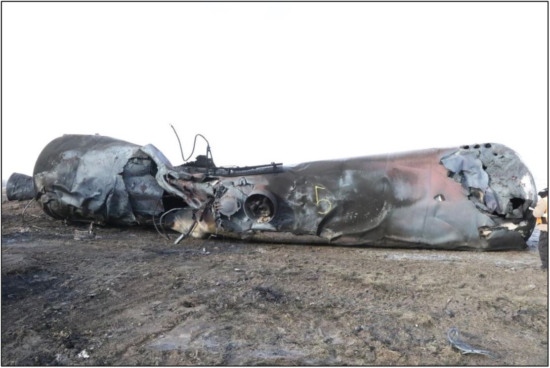
Several tank car shells, heads as well as wheels and axles of various cars were melted (figures 8 and 9). This indicated that the fire had reached temperatures in excess of 1340 °C, which is the minimum melting temperature of carbon steel.
There was a total of 6 top fitting (3) and manway (3) breaches. However, 2 of these 6 breaches were associated with large shell failures. Both of these cases were considered to be a secondary product release point since most, if not all, of the release would have been almost instantaneous through the large shell failure.
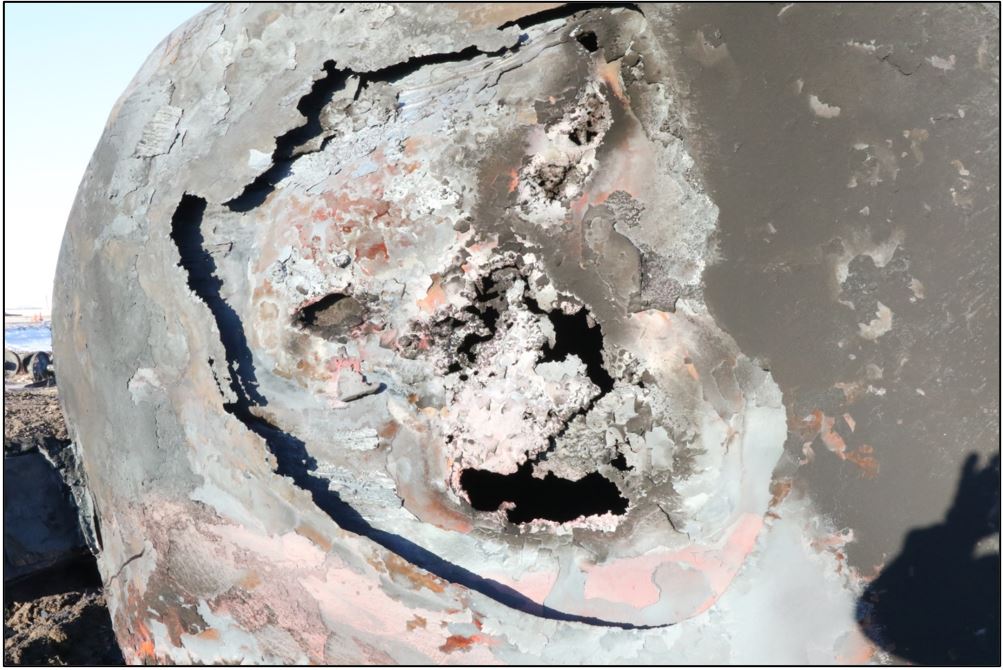
Although evidence of potential thermal tears was observed, the thermal tears could not be confirmed with any certainty due to the extensive tank car damage (Figure 10).
No BOVs were identified as having breached and released product; however, the extensive fire and remediation damage made it impossible to determine the performance of either the original or the improved BOV assemblies.
1.23 TSB Watchlist
The TSB Watchlist identifies the key safety issues that need to be addressed to make Canada’s transportation system even safer.
Safety management is a Watchlist 2022 issue. As this occurrence demonstrates, despite railways having detailed safety management system plans and risk assessments that identify mitigation strategies to minimize potential hazards that can lead to a derailment, there are often gaps in the risk assessment, and accidents sometimes occur before mitigations are fully implemented.
ACTIONS REQUIRED Safety management will remain on the Watchlist for the rail transportation sector until operators demonstrate to TC that their SMS is effective. |
1.24 TSB laboratory reports
The TSB completed the following 2 laboratory reports in support of this investigation:
- LP011/2020 – Tank car examination
- LP150/2021 – Examination of product characteristics
2.0 Analysis
Canadian Pacific Railway Company (CP) freight train 516-398, a unit train carrying petroleum crude oil (UN1267, Class 3, Packing Group [PG] I), was operated in accordance with regulatory requirements. The actions of the train crew were not considered to be contributory to the accident. The analysis will focus on the condition of the track infrastructure, the detection of broken rails and broken joints, train speed, and gaps in CP’s risk assessment process with regards to the Safety Management Systems Regulations, 2015 (SMS Regulations) and the 2016 Rules Respecting Key Trains and Key Routes (KTR) requirements.
Since there has been interest throughout North America in how tank cars perform during derailments, the results of detailed tank car examination, product analysis, and observations of both will also be discussed.
2.1 The accident
On 09 December 2019 at about 0010 Central Standard Time, the train was proceeding eastward at 44 mph on the Sutherland Subdivision, governed by the occupancy control system (OCS), near Guernsey, Saskatchewan, when the crew observed a gap in the south rail as the train was approaching the public passive crossing at Wolverine Road (Mile 48.85).
Video from the head-end locomotive (CP 8946) forward-facing video camera confirmed that there was a gap in the south rail at about Mile 48.86, which was about 50 feet west of the Wolverine Road crossing (Mile 48.85). When the locomotive traversed the gap, there was a noticeable vibration in the locomotive cab and the recorded image. Immediately afterward, a train-initiated emergency brake application occurred and the crew members observed a large explosion behind them as the head-end locomotive and first car separated from the train.
The first car behind the head-end locomotive, a covered hopped car loaded with sand, derailed but remained coupled to the locomotive. All of the locomotive’s south wheels exhibited transverse impact marks on the wheel treads. The marks were consistent with the wheels having contacted the south rail head that was left exposed after an undetermined length of the rail had broken away from the track, likely under a previous CP train, prior to the arrival of train 516-398. It was not possible to identify the precise nature of the rail failure because the section of the south rail that had broken away was not recovered.
Subsequent inspection determined that 34 cars had derailed, including 33 tank cars loaded with petroleum crude oil (crude oil). As the derailment occurred, 20 tank cars breached and released their contents. The released product ignited, which resulted in a large pool fire that burned for about 24 hours and destroyed 19 of the derailed tank cars. It is estimated that approximately 1.77 million litres of crude oil was released. No evacuation was required. No one was injured.
Findings as to cause and contributing factors
The derailment occurred when the CP crude oil unit train traversed a gap in the south rail as it travelled eastward on the Sutherland Subdivision in the vicinity of Mile 48.86.
The south rail had likely failed under a previous train, causing an undetermined length of rail to break away and separate from the track and expose the rail ends.
2.2 Sutherland Subdivision track inspection
To protect against the potential of broken joints and broken rails to create a rail gap and cause a derailment, and in accordance Rules Respecting Track Safety, also known as the Track Safety Rules (TSR), CP conducted regular track visual inspections and ultrasonic rail flaw detection (RFD) tests.
From September to December 2019, CP’s visual inspections identified 11 broken joints and 2 broken rails that had to be repaired before the passage of a train.
For the Sutherland Subdivision, CP exceeded the TSR minimum requirement of 3 RFD inspections annually for Class 4 continuous welded rail (CWR) track with an annual tonnage of between 15 and 35 million gross tons. In 2019, CP conducted 7 RFD inspections on the subdivision and identified a total of 87 defects that were repaired by cutting out the rail defect and installing a plug rail.
Finding as to cause and contributing factors
Despite regular track visual inspections and RFD testing, which exceeded regulatory requirements, the broken south rail in OCS territory went undetected before the arrival of the train and caused the derailment of a key train on a key route that resulted in the release of 1.77 million litres of crude oil.
2.3 Longitudinal rail restraint
In CWR territory, such as the Sutherland Subdivision, broken rails and joints are symptomatic of inadequate longitudinal rail restraint and are more likely to occur in cold ambient temperatures.
To provide the necessary resistance to longitudinal forces under normal service loads, the rail must be properly supported and secured. It is important that all track components—rail anchors, ties, and ballast—perform as designed and that the rail’s neutral temperature be properly managed.
Rail anchors hold the rail in place and transmit the longitudinal forces generated by the passage of a train to the ties. The ties, embedded in the ballast, absorb the forces, which are then transferred to the subgrade. If one or more of the track components is not contributing to the expected resistance, the potential for track irregularities increases. For example, if anchors are not applied to sound ties, they will not provide the expected restraint. Similarly, pit run ballast that consists of small rounded stones with relatively few fracture faces may not provide adequate restraint for the ties embedded in the ballast.
In the area of the derailment, 25% of the ties were defective. Anchors that are applied to defective ties will not provide the expected restraint.
The pit run ballast in this occurrence consisted mostly of stones that were small (up to 4-inch-diameter) and rounded. Sound ballast usually has crushed rock that has rough angular surfaces, which allow the stones to interlock with the ties and with each other to form a stable subgrade. In comparison, the small, rounded stones in pit run ballast have fewer fracture faces for interlocking with the ties and each other so the ties are less likely to embed into ballast.
At the time of the accident, the temperature was −19 °C. In the 12 hours preceding the accident, the temperature averaged −19.3 °C. As temperatures cool in CWR territory, the rail contracts and is subjected to longitudinal tensile forces. In this case, the cold ambient temperature created favourable conditions for a broken rail to occur.
All of the conditions noted above existed in the vicinity of the derailment and likely contributed to the development of the broken rail. If the track structure does not have adequate restraint, tensile forces can lead to broken rails, resulting in rail gaps, which can cause a derailment.
Finding as to cause and contributing factors
The track components (anchors, ties, and ballast) did not provide adequate resistance to the rail longitudinal tensile forces initiated by the cold weather, which contributed to the breaking of the rail under normal service loads by the passage of a prior train.
2.4 Detection of broken rails and broken joints
On subdivisions where train movements are governed by a signalled centralized traffic control system (CTC), wayside signals are installed along the railway right-of-way to govern train movements. The signals are connected by track circuits that operate through the rails. A broken rail or joint that results in a rail gap in CTC territory will likely interrupt the track circuit, which causes the signals that govern the movements to “fail safe” and display the most restrictive indication, usually a red (stop) signal. If this occurs, a train must come to a stop or receive permission to pass a stop signal from a rail traffic controller and then proceed through the block at restricted speed (15 mph) while being on the lookout for broken rails. This provides trains operating in CTC territory with some measure of protection against derailments due to broken rails and broken joints.
For trains operating in OCS territory, such as the Sutherland Subdivision, there are no wayside signals installed along the railway right-of-way to govern train movements. Consequently, as demonstrated by this accident, broken rails that result in a rail gap can go undetected in OCS territory until observed by the crew of an approaching train, by which time it may be too late to slow or stop the train before it encounters a broken rail.
2.5 Track maintenance and severity of derailments
The National Research Council Canada study on factors that increase the severity of derailments involving dangerous goods (DG) noted that there is a complex relationship between train speed, train length, accident cause, and other factors that influence the severity of an outcome from a derailment. While there appears to be a linear relationship between the number of cars that derail and the speed of the train at the time of an accident, speed is not the only factor.
The study looked at various train profiles and compared them to DG unit trains. The results of how derailments may differ for the various train profiles were then compared. A unit train consisting of all DG cars, such as unit trains transporting tank cars loaded with crude oil, was identified as having the highest risk profile, which means that DG unit trains present the greatest risk in the event of a derailment.
Derailments caused by broken rails, broken rail welds, or broken joint bars had a much higher occurrence rate and derailed more cars per accident for a given speed. As speed increased, these types of derailments resulted in more severe accidents compared to derailments due to other causes. In particular, loaded unit trains (including non-key unit trains) derailed more cars and were also involved in a larger percentage of these types of accidents. All these factors were present in this accident.
While improved tank car structure design has been shown to reduce the probability of a DG release and the potential severity of an accident, it does not reduce the likelihood of a derailment or influence the number of cars that derail. The risk of a tank car being punctured/breached and releasing product exists in any derailment if the speed is sufficiently high.
For example:
- On 14 February 2015, a Canadian National Railway Company (CN) crude oil unit train derailment occurred at Mile 111.7 of the Ruel Subdivision near Gladwick, Ontario. The train was travelling at 38 mph at the time of the accident. Of the 29 derailed tank cars, 19 (66%) were breached and about 1.7 million litres of product was released to the surface and atmosphere. The investigation determined that the derailment occurred when an insulated rail joint in the south rail at Mile 111.7 failed beneath the head end of the train.
- On 07 March 2015, another CN crude oil unit train derailment occurred at Mile 88.70 of the Ruel Subdivision, near Gogama, Ontario. The train was travelling at 43 mph at the time of the accident. The investigation determined that, before the arrival of the train, a 16-inch-long portion of the parent south rail head had broken off due to a vertical split head rail failure within the east joint of a recent plug rail repair, leaving a gap in the south rail. The derailment occurred when the south rail failed beneath the train as it traversed the track, resulting in the derailment of the 6th to 44th (39) tank cars. As a result of the derailment, 33 cars (85%) were breached and about 2.6 million litres of crude oil was released.
-
On 16 February 2019, a CN unit train, consisting of 108 tank cars loaded with crude oil and 2 covered hopper cars loaded with sand, was proceeding eastward on the Rivers Subdivision at about 49 mph when it experienced a train-initiated emergency brake application near St. Lazare, Manitoba. A subsequent inspection determined that 37 TC/DOT Class 117R tank cars had derailed near Mile 197.47. A total of 17 of the derailed tank cars were breached, which resulted in the release of about 815 000 litres of product. About 1000 feet of track was damaged or destroyed. There was no fire, there were no injuries, and no evacuation was required.
The investigation determined that the accident occurred due to a misaligned joint that failed under the train.
All 3 of these derailments occurred as a result of inadequate track maintenance and related rail or joint conditions. Improved track repair and maintenance for key routes reduce the likelihood of all derailments, including those involving DG. Following these 3 accidents, CN made major infrastructure improvements to both subdivisions and, at the time of writing this report, there has not been a serious main-track accident on either subdivision since the infrastructure improvements were made.
2.5.1 Indications of track requiring additional maintenance on the Sutherland Subdivision
The frequency of CP’s track geometry and RFD inspection exceeded the TSR minimum requirements. Despite the increased testing frequency, there were a number of indicators that identified that the condition of the track infrastructure on the subdivision required additional maintenance. For example:
- In August 2018, Transport Canada (TC) issued a Letter Of Non-Compliance And Concern to CP in which TC identified 79 non-compliant tie conditions that required immediate attention.
- In 2019, TC inspected 166 miles of track on the Sutherland Subdivision. The inspections revealed a total of 31 defects that required immediate attention. The same TC inspection also identified 223 track conditions that were approaching the TSR minimum requirements.
- Although the Sutherland Subdivision only required 2 track geometry inspections per year, in 2019, CP conducted 3 geometry inspections and identified a total of 220 urgent defects that required repair. Of the 220 urgent defects detected on the Sutherland Subdivision in 2019, the most common defects identified were for narrow gauge (117), design elevation related to cross-level (56), and other surface conditions (24).
- The number of urgent track geometry defects detected was indicative of a track requiring additional maintenance. In particular, the high number of narrow-gauge defects (117) identified that the condition of the track structure in various locations was no longer able to maintain track gauge under dynamic conditions. On tangent track, narrow gauge promotes an unstable ride for rolling stock, which contributes to truck hunting as well as accelerated wheel and rail wear.
- The Sutherland Subdivision only required 3 RFD inspections per year, but in 2019, CP conducted 7 RFD inspections and identified a total of 87 defects that required repair. Given the age of the rail on the subdivision (circa 1960s to 1980s), the number of defects was indicative of track that required additional maintenance.
- At the time of this accident, despite a joint elimination program, the Sutherland Subdivision had about 700 joints remaining in CWR territory, many related to plug rail repairs to address RFD defects, which further indicated that the condition of the Sutherland Subdivision CWR track infrastructure required additional maintenance.
This accident and the 3 previous accidents shared some common elements. Specifically,
- All 4 accidents involved crude oil unit trains operating on key routes.
- Over time, the subdivisions involved required additional maintenance as evidenced by the significant number of geometry and RFD defects, plug rail repairs, and related joint repairs in CWR territory.
- All 4 accidents occurred primarily as a result of inadequate track maintenance and related joint or rail conditions.
While the TSR established minimum standards for track infrastructure, some CP requirements exceed the TSR requirements. However, at the time of this occurrence, neither the TSR nor CP requirements addressed the need for enhanced track standards for key routes despite significant increases in DG traffic volumes and multiple indicators of deteriorating track infrastructure conditions, as occurred on the Sutherland Subdivision. This suggests that the regulatory and company track maintenance requirements in place at the time of the occurrence may not have been sufficient to protect against derailments involving DG on key routes.
To reduce the frequency and mitigate the risks associated with accidents involving key trains on key routes, it is imperative that the key route track infrastructure be adequately maintained. While the survivability of tank cars transporting DG becomes important after an accident, the most effective strategy is to address the underlying causes of accidents to prevent them from occurring in the first place. Since the regulatory and company track maintenance requirements in place at the time of the accident did not protect against these accidents, enhanced regulatory and company track maintenance requirements for key routes could be a viable prevention strategy.
Findings as to risk
If accident prevention strategies do not include enhanced regulatory and company track maintenance requirements for key routes, there is an increased risk that a rail or joint failure on a key route will cause a derailment and a subsequent DG release.
The operation of key trains on key routes in OCS territories that have no secondary means to protect against a broken rail resulting in a rail gap presents an increased risk to the public and environment in the event of a derailment involving a key train.
Train speed
Examination of previous derailments involving tank cars indicated that, when crude oil unit trains derail, there are typically 3 major zones within a derailment area:
- The initial zone is where tank cars scatter randomly and usually retain shell integrity during the derailment, and there is less tank deformation, resulting in smaller impact dents or breaches. The volume of product released is usually lower in this zone as compared to the main body of the derailment.
- The second zone contains the main body of the derailment where the tank cars generally jackknife, align side by side, and/or stack up. These tank cars account for the majority of the breaches and volume of product released due to the large dynamic forces that the tank cars experience. The first derailed car acts as an anchor while the force from the trailing cars imparts large loads on the derailed cars that have come to rest, which often results in large tank deformations or punctures.
- The third and final zone is at the tail end of the derailment where the remaining tank cars that derail usually scatter randomly, but do not stack up. Tank cars located in the tail end of the derailment can have a wide range of damage and product release, but generally the trailing tank car speed and related impact forces are reduced, which typically results in less tank damage and associated product loss.
The reasons for the derailed tank car performance in each zone vary, but the most common elements include the speed of the train at the time of the derailment, the size of the derailment area, the topography of the derailment area, and the ambient temperature at the time of the derailment. All of these factors played a role in this occurrence.
In this occurrence, the train was proceeding at 44 mph when the accident occurred. A total of 33 tank cars derailed, 20 of which sustained breaches and released about 1.77 million litres of crude oil. The temperature at the time of the accident was −19 °C.
The circumstances related to crude oil unit train speed, the number of cars derailed, and some of the tank car damage observed in this occurrence were similar to other major accidents involving crude oil unit trains that the TSB has investigated. These circumstances were also consistent with the National Research Council Canada Study on the Factors that Increase the Severity of the Outcomes for Derailments Involving Dangerous Goods and Identification of Mitigation Measures.
Finding as to causes and contributing factors
Although the CP crude oil train was operated in accordance with the Rules Respecting Key Trains and Key Routes, similar to other major accidents involving crude oil unit trains, the train speed (44 mph) contributed to the number of cars derailed and the number of cars that breached and lost their product.
2.7 Safety management system and Sutherland Subdivision risk assessments
The SMS Regulations require that a railway company conduct a risk assessment when a proposed change to its railway operations, which includes an increase in the volume of DG it transports, may affect the safety of the public or personnel or the protection of property or the environment. Despite yearly increases in crude oil DG traffic on the Sutherland Subdivision, there were no risk assessments conducted in either 2018 or 2019.
The KTR required that companies conduct key route risk assessments, at a minimum of every 3 years, and CP conducted key route risk assessments for the Sutherland Subdivision in 2014 and 2017. The CP risk assessments evaluated 28 factors, including traffic density, prescribed in the KTR for the assessment of safety- and security-related risks associated with each key route.
The risk assessments did not consider the defect frequency of urgent track geometry defects, or RFD defects, on the Sutherland Subdivision, which could be a useful indicator as to the overall condition of the track infrastructure used to transport DG.
Furthermore, between 2015 and 2019, rail traffic tonnage on the subdivision increased by 60% and the transport of crude oil increased by over 66 000 car loads. Most of the crude oil was transported by CP unit trains consisting of Class 111 tank cars that were built to the CPC-1232 standard and had a GRL capacity of 286 000 pounds. This represented an increase of 23 000-pound GRL capacity per tank car when compared to the older legacy Class 111 tank car GRL capacity of 263 000 pounds. Although the track in the vicinity of the derailment was continually maintained to Class 4 standards, the potential for more rapid degradation of aging track infrastructure due to a 60% increase in traffic tonnage, much of which was transported in heavier rail cars, was also not identified in the risk assessment.
Effective safety management requires the identification of systemic risks or issues to assist in the prevention of accidents. Despite the existence of risk assessments for the Sutherland Subdivision that took into account various elements of the track infrastructure required to eliminate potential derailment hazards, the CP risk assessments did not identify the risks associated with aging infrastructure and the increasing volume of crude oil traffic being transported in heavier tank cars between 2015 and 2019.
Finding as to risk
If company risk assessments do not adequately consider increases in traffic tonnage, the use of heavier rail cars, and the potential for more rapidly degrading track structure, regular track maintenance activities may no longer be sufficient to maintain track to the required standards, increasing the risk of track infrastructure failures that lead to rail accidents.
2.8 Factors that contributed to the volume of product loss and the fire intensity
Three conditions must be fulfilled for ignition of released crude oil to occur: Footnote 53
- The material must produce sufficient quantities of vapours or gases;
- The vapours or gases must be mixed with a sufficient quantity of oxygen; and
- The air-vapour mixture must be at a temperature high enough to auto-ignite or a source of ignition such as a spark, small flame, or superheated metal part (from friction) must be present.
Since all of these factors were present in this occurrence, the conditions were ideal for ignition to occur once the product was released. There were also other factors that contributed to the volume of product loss and the fire intensity. Specifically:
- The relatively short derailment zone (about 500 feet) increased the dynamic impact energy on the tank cars during the derailment and resulted in more significant breaches.
- The crude oil was blended with 32% diluent, which increased the amount of the product vapour that was able to escape the breached cars.
- The relatively high viscosity of the crude oil blend (58.76 cST at 40 °C), combined with the −19 °C cold temperature at the time of the derailment, would have slowed the flow of some product. This allowed product to pool under the derailed tank cars located in the main body of the derailment and further increase the volume of crude oil that was available to fuel the fire.
- The vapour pressure of 51.7 kPa, the low flashpoint of <40 °C and the relatively low initial boiling point of 33.2 °C all increased the likelihood of vapour ignition upon release either through a breach or pressure relief device activation.
- Once the fire ignited, it heated the exposed tank cars in the main body of the derailment, which increased their internal pressure to the point where the pressure relief device began to activate. The activation of these devices released more vapour/product, which further fed the pool fire.
- The large pool of product was further concentrated due to the topography of the derailment zone. The embankment of Wolverine Road prevented the flow of the product away from the main body of the derailment in the westerly direction. This allowed the product to feed the fire for a longer period of time than if the product had been allowed to drain off.
Finding as to cause and contributing factors
The dynamics of the derailment, the properties of the crude oil blend, and the topography of the derailment location all played a role in the damage sustained by the tank cars, the amount of product lost, and the intensity of the pool fires.
2.8.1 Reducing the volatility of crude oil for safer transport by rail
There are several methods to reduce the volatility of crude oil being transported by rail to make it less susceptible to unintended ignition. These methods include conditioning and stabilizing the crude oil, and reducing the diluent blend ratio.
Finding as to risk
If the volatility of the crude oil being transported by rail is reduced, it is less likely that crude oil released as a result of an accident will ignite and/or explode, reducing the risks to people, property, or the environment.
2.9 Tank car performance
As part of its mandate, the TSB makes recommendations to eliminate or reduce safety deficiencies that pose significant risks to the transportation system and warrant the attention of regulators and industry. The TSB continually monitors the progress being made on its active recommendations. This required the TSB to perform a detailed evaluation of the tank car damage in order to evaluate the cars’ performance in the derailment.
In this occurrence, 20 of the 33 derailed tank cars released product after sustaining damage; 15 of the 20 cars lost their entire contents, and the other 5 lost approximately 60% of their contents.
Seventeen of the 20 tank cars that breached (81%) were engulfed in the main pool fire.
The 19 tank cars in the pool fire (zone 2) were extensively damaged by fire. The tank car identification markings (stenciling and stamping) on 16 of the tank cars in the pool fire were obliterated to the point that the 16 cars could not be identified.
While evidence of potential thermal tears was observed, the presence of thermal tears could not be confirmed with any certainty due to the extent of the tank car damage.
Although no bottom outlet valves were breached or released product, the extensive fire and remediation damage made it impossible to evaluate the performance of either the original or the improved bottom outlet valves assemblies.
Other findings
The intensity of the pool fire melted tank shells, heads, wheels, and axles of various cars, indicating that the fire reached temperatures in excess of 1340 °C, which is the minimum melting temperature of carbon steel.
Due to the extensive tank car derailment damage, fire damage, and some remediation damage, a comprehensive evaluation of the performance of the tank cars involved in this derailment was not possible.
3.0 Findings
3.1 Findings as to causes and contributing factors
These are conditions, acts or safety deficiencies that were found to have caused or contributed to this occurrence.
- The derailment occurred when the Canadian Pacific Railway Company crude oil unit train traversed a gap in the south rail as it travelled eastward on the Sutherland Subdivision in the vicinity of Mile 48.86.
- The south rail had likely failed under a previous train, causing an undetermined length of rail to break away and separate from the track and expose the rail ends.
- Despite regular track visual inspections and rail flaw detection testing, which exceeded regulatory requirements, the broken south rail in occupancy control system territory went undetected before the arrival of the train and caused the derailment of a key train on a key route that resulted in the release of 1.77 million litres of crude oil.
- The track components (anchors, ties, and ballast) did not provide adequate resistance to the rail longitudinal tensile forces initiated by the cold weather, which contributed to the breaking of the rail under normal service loads by the passage of a prior train.
- Although the Canadian Pacific Railway Company crude oil train was operated in accordance with the Rules Respecting Key Trains and Key Routes, similar to other major accidents involving crude oil unit trains, the train speed (44 mph) contributed to the number of cars derailed and the number of cars that breached and lost their product.
- The dynamics of the derailment, the properties of the crude oil blend, and the topography of the derailment location all played a role in the damage sustained by the tank cars, the amount of product lost, and the intensity of the pool fires.
3.2 Findings as to risk
These are conditions, unsafe acts or safety deficiencies that were found not to be a factor in this occurrence but could have adverse consequences in future occurrences.
- If accident prevention strategies do not include enhanced regulatory and company track maintenance requirements for key routes, there is an increased risk that a rail or joint failure on a key route will cause a derailment and a subsequent dangerous goods release.
- The operation of key trains on key routes in occupancy control system territories that have no secondary means to protect against a broken rail resulting in a rail gap presents an increased risk to the public and environment in the event of a derailment involving a key train.
- If company risk assessments do not adequately consider increases in traffic tonnage, the use of heavier rail cars, and the potential for more rapidly degrading track structure, regular track maintenance activities may no longer be sufficient to maintain track to the required standards, increasing the risk of track infrastructure failures that lead to rail accidents.
- If the volatility of the crude oil being transported by rail is reduced, it is less likely that crude oil released as a result of an accident will ignite and/or explode, reducing the risks to people, property, or the environment.
3.3 Other findings
These items could enhance safety, resolve an issue of controversy, or provide a data point for future safety studies.
- The intensity of the pool fire melted tank shells, heads, wheels, and axles of various cars, indicating that the fire reached temperatures in excess of 1340 °C, which is the minimum melting temperature of carbon steel.
- Due to the extensive tank car derailment damage, fire damage, and some remediation damage, a comprehensive evaluation of the performance of the tank cars involved in this derailment was not possible.
4.0 Safety action
4.1 Safety action taken
4.1.1 Transportation Safety Board of Canada
Following this accident and a second serious Canadian Pacific Railway Company (CP) crude oil unit train derailment near Guernsey, Saskatchewan, that occurred about 2 months later (06 February 2020, TSB Occurrence R20W0025), on 04 March 2020, the TSB issued rail safety advisories (RSA) 02/20 and 03/20 to Transport Canada (TC).
The RSAs noted that, since 2015, including this accident, the TSB had deployed to 7 train derailments involving tank cars that were transporting crude oil, 6 of which resulted in a significant release of product. A review of the 7 accidents revealed the following:
- All 7 derailments occurred on a key route on which the track was maintained in accordance with the Rules Respecting Track Safety, also known as the Track Safety Rules (TSR), Class 3 or 4 standard.
- All 7 derailments occurred as a result of a broken rail, broken joint bars, or other track infrastructure condition.
- For 6 of the 7 cases:
- Train speed ranged from 38 mph to 49 mph.
- Between 29 and 39 tank cars loaded with petroleum crude oil derailed.
- A total of 8.43 million litres of petroleum crude oil was released.
- The derailment occurred during the winter months.
4.1.1.1 Rail Safety Advisory 02/20 – Modifying key train speed based on various train risk profiles
In RSA 02/20, the TSB indicated that train speed is one of the primary factors that contributes to the severity of a derailment. However, other factors such as train length, train weight, the position of the first car(s) derailed, the position of the cars in the train, and tank car design also play a role. The RSA suggested that, to reduce the frequency of these accidents and the commensurate risk to the public, property, and the environment, TC should further review and modify key train speeds, as appropriate, based on various train risk profiles while also considering other factors that influence the severity of a derailment.
4.1.1.2 Rail Safety Advisory 03/20 – Enhanced track standards for key routes
In RSA 03/20, the TSB noted that, as train operations have evolved, the TSR have not kept pace. The current TSR came into force on 25 May 2012, almost 4 years before the TC-approved Rules Respecting Key Trains and Key Routes came into force in February 2016. While the TSR establish minimum standards for track infrastructure, there are no provisions in the TSR to address the need for enhanced track standards for key routes despite sometimes significant increases in dangerous goods traffic volumes on these routes.
To reduce the frequency and mitigate the risks associated with accidents involving key trains on key routes, it is imperative that the track infrastructure be adequately maintained. Considering that the underlying causes of the 7 accidents identified were all related to failures of the track infrastructure, TC was advised that the current TSR do not address the increased risks associated with the operation of key trains. The TSB suggested that TC consider revising the TSR to include enhanced track standards for key routes.
4.1.2 Transport Canada
4.1.2.1 Revision of the Rules Respecting Key Trains and Key Routes
In response to RSA 02/20, TC issued a number of ministerial orders (MO), including the following.
4.1.2.1.1 Ministerial Order MO 20-05 issued pursuant to section 32.01 of the Railway Safety Act
On 01 April 2020, TC issued MO 20-05, which indicated that, pursuant to the provisions of section 32.01 of the Railway Safety Act, federally regulated railway companies were ordered to implement additional safety measures for key trains.
The MO identified that there were a number of recent derailments of trains transporting dangerous goods that resulted in the breach of tank cars and the release of dangerous goods, including the Canadian National Railway Company (CN) St. Lazare derailment in Manitoba in 2019, and the 2 CP derailments on the Sutherland Subdivision in Saskatchewan in 2019 (this occurrence) and 2020, respectively.
Federally regulated railways were ordered to implement an additional definition for a higher-risk key train, which was defined as an engine with cars that include loaded tank cars carrying crude oil or liquefied petroleum gases, as defined in the Transportation of Dangerous Goods Act, 1992, in a continuous block of 20 or more tank cars, or 35 or more tank cars dispersed through a train.
The MO also included additional speed restrictions, requirements for continuous welded rail (CWR) joint management, and requirements for installing replacement (plug) rail.
MO 20-05 was effective immediately, with the exception of the requirements for CWR joint management and installing replacement (plug) rails, which were planned to come into effect on 01 September 2020. This MO remained in effect until the Minister approved the revised Rules Respecting Key Trains and Key Routes that incorporated the above measures on a permanent basis.
4.1.2.1.2 Ministerial Order MO 20-06 issued pursuant to section 19 of the Railway Safety Act
On 01 April 2020, TC issued MO 20-06 pursuant to the provisions of paragraph 19(1)(a) of the Railway Safety Act. The MO ordered federally regulated railway companies to revise the Rules Respecting Key Trains and Key Routes.
The MO required that revised rules be based on an assessment of safety risk and, at a minimum, incorporate the following:
- new definitions, including the definition for “higher-risk key trains,” which is to be defined as “an engine with cars that include loaded tank cars carrying crude oil or liquefied petroleum gases, as defined in the Transportation of Dangerous Goods Act, 1992, in a continuous block of 20 or more tank cars, or 35 or more tank cars dispersed through a train;”
- additional speed restrictions;
- requirements for CWR joint management; and
- requirements for installing replacement (plug) rail.
The MO required that railways file the revised Rules Respecting Key Trains and Key Routes with the Minister of Transport for approval within 210 days of the date that the MO was issued.
4.1.2.1.3 Ministerial Order MO 20-10 issued pursuant to section 32.01 of the Railway Safety Act, M2O-05 repealed
On 06 November 2020, TC issued MO 20-10 pursuant to the provisions of section 32.01 of the Railway Safety Act. With the issuance of MO 20-10, MO 20-05 was repealed, and federally regulated railway companies were ordered to implement additional safety measures for key trains, which included the following:
- Part I: Additional key train speed restrictions when a winter operation risk mitigation plan is not in place
- Part II: Requirement for Continuous Welded Rail Joint Management
- Part III: Requirement for installation of replacement (plug) rail
- Part IV: Key train speed restrictions with a winter operation risk mitigation plan in place
- Part V: Requirements for winter operation risk mitigation
- Part VI: Requirements for Rail Break Detection Technology
This order was effective immediately and remained in effect until the Minister approved the revised Rules Respecting Key Trains and Key Routes that incorporated the above measures on a permanent basis.
4.1.2.1.4 Revised Rules Respecting Key Trains and Key Routes
On 22 February 2021, TC approved the revised Rules Respecting Key Trains and Key Routes submitted by the industry. The revised rules came into effect on 22 August 2021. Footnote 54 The revised rules
- require companies to develop and adhere to a maintenance and inspection plan for permanent rail joints and temporary rail joints in CWR;
- The inspection plan is to include time limits for the retention of temporary rail joints until permanently repaired, as well as the requirement for records detailing the location, installation, inspection, and maintenance dates for temporary rail joints.
- restrict the maximum operating speed of key trains in census metropolitan areas (CMAs);
- define higher-risk key trains as those trains that include loaded tank cars carrying crude oil or liquefied petroleum gases in a continuous block of 20 or more tank cars or 35 or more tank cars dispersed through a train;
- further restrict the maximum operating speed of higher-risk key trains, when compared to key trains operating both within and outside of CMAs;
- contain new requirements for Winter Operation Risk Mitigation Plans;
- restrict operating speeds for higher-risk key trains for railway companies without Winter Operation Risk Mitigation Plans; and
- contain specific requirements for broken rail detection technology.
4.1.2.2 Revision of the Rules Respecting Track Safety
In response to RSA 03/20, TC issued MO 20-07.
4.1.2.2.1 Ministerial Order MO 20-07 issued pursuant to section 19 of the Railway Safety Act
On 01 April 2020, TC issued MO 20-07, which indicated that, pursuant to the provisions of paragraph 19(1)(a) of the Railway Safety Act, federally regulated railway companies were ordered to revise the TSR.
The revised TSR should be based on an assessment of safety risks, track-related derailment causes, evolving technology, current railway internal standards, and industry best practices, and shall, at a minimum, address the following elements in 3 phases:
Phase 1 elements
- Training, qualification, and quality assurance
- CWR management
- Track geometry
- Rail wear management
- Rail surface management
Phase 2 elements
- Track inspection frequency
- Automated track inspection technology
Phase 3 – Structures / Other elements
- Requirement for concrete ties
- Requirement for inspection of yard tracks over which passenger equipment carrying passengers operates
- Requirements to develop and report on key track performance indicators
- Requirement to file with TC the most recent version of company track standards
The dates for filing the revised TSR with the Minister were 01 April 2021 (Phase 1), 01 October 2021 (Phase 2), and 01 April 2022 (Phase 3).
On 31 May 2021, TC approved the Phase 1 revisions to the TSR. Part I, section 9, items b) through f) of the revised TSR include quality assurance requirements for safety-critical maintenance and repair activities.Footnote 55 The list of safety-critical maintenance and repair activities for key routes must be approved by a professional engineer. These quality assurance requirements are expected to decrease the likelihood of derailments resulting from repair and maintenance activities that are inconsistent with the railway company’s standards and procedures.
Part II, Subpart D, section IX of the revised TSR includes requirements for CWR Management Plans that contain comprehensive installation, inspection, and maintenance requirements.Footnote 56
The revised TSR also include requirements for railway companies to prepare and adhere to Track Geometry Management Plans, Rail Surface Management Plans, and Rail Wear Management Plans. Track Geometry Management Plans for key routes must include instructions for monitoring and taking appropriate measures for geometry conditions approaching the limits prescribed under the TSR.
As of 31 May 2023, all 3 phases have been completed and are in effect.
4.1.3 Canadian Pacific Railway Company
In response to this occurrence and subsequent derailments that occurred on subdivisions governed by the occupancy control system, CP has implemented its own wayside system for the detection of track discontinuities in non-signalled territory. The system can detect broken rails and indicate the presence of trains. It works by sending a low-voltage signal through the rails and relies on technology found in other industries, such as solar cells, lithium ion batteries, and miniaturized signal-processing circuits. Territory equipped with this system would still be considered dark territory.
Since the occurrence, CP has added 2 more autonomous track geometry measuring systems and is building another one, which will bring the total to 5.
A summary of the track work conducted by CP on the Sutherland Subdivision in 2020 is contained in Table 10 below:
| Track work | Units | 2020 |
|---|---|---|
| New rail/relay rail | miles | 19.73 |
| Ties replaced | each | 76 086 |
| Joint elimination | each | 845 |
| Turnouts installed | each | 10 |
| Track surfacing | feet | 441 651 |
At September 2023, there had been no main-track derailments on the CP Sutherland Subdivision since CP completed the track work.
This report concludes the Transportation Safety Board of Canada’s investigation into this occurrence. The Board authorized the release of this report on . It was officially released on .
Appendices
Appendix A – Summary of tank car breaches
| Location of tank car in train (line) | TSB-assigned identity number | Type of breach |
|---|---|---|
| 2 | n/a | No breach |
| 3 | n/a | No breach |
| 4 | 18 | No breach |
| 8 | 1 | Shell |
| 11 | 5 | Shell |
| 20 | n/a | No breach |
| 23 | n/a | No breach |
| 24 | n/a | No breach |
| 25 | n/a | No breach |
| 26 | n/a | Shell |
| 27 | n/a | No breach |
| 28 | n/a | Head |
| 29 | n/a | Shell |
| 30 | n/a | No breach |
| 31 | n/a | No breach |
| 32 | n/a | No breach |
| 33 | n/a | No breach |
| 34 | n/a | No breach |
| n/a | 2 | Manway |
| n/a | 3 | Shell |
| n/a | 4 | Shell and head |
| n/a | 6 | Shell, top fittings and pressure relief devices, and manway |
| n/a | 7 | Shell |
| n/a | 8 | Shell |
| n/a | 9 | Shell |
| n/a | 10 | Shell, top fittings and pressure relief devices, and manway |
| n/a | 11 | Shell and head |
| n/a | 12 | Shell |
| n/a | 13 | Shell |
| n/a | 14 | No breach |
| n/a | 15 | Shell and head |
| n/a | 16 | Top fittings and pressure relief devices |
| n/a | 17 | Shell |
| n/a | 19 | Shell |
Total number of breaches:
- Shell breaches: 17
- Head breaches: 4
- Top fittings and pressure relief devices: 3
- Manway: 3
- Bottom outlet valve: 0