Runway excursion
Calm Air International LP
Avions de Transport Régional ATR 42-300, C-FAFS
Naujaat Airport, Nunavut
The Transportation Safety Board of Canada (TSB) investigated this occurrence for the purpose of advancing transportation safety. It is not the function of the Board to assign fault or determine civil or criminal liability. This report is not created for use in the context of legal, disciplinary or other proceedings. See Ownership and use of content. Masculine pronouns and position titles may be used to signify all genders to comply with the Canadian Transportation Accident Investigation and Safety Board Act (S.C. 1989, c. 3).
Summary
On 26 November 2020, the Calm Air International LP Avions de Transport Régional ATR 42-300 aircraft (registration C-FAFS, serial number 298) was conducting flight CAV464 under instrument flight rules from Rankin Inlet, Nunavut, to Naujaat, Nunavut, with 3 crew members on board. While on descent, the crew observed abnormally low propeller rpm indications on the left engine. At 1326 Central Standard Time, shortly after touchdown on Runway 34 at Naujaat Airport, directional control was lost and the aircraft experienced a runway side excursion on the east side of the runway. The aircraft came to rest approximately 108 feet from the runway edge. The captain received serious injuries. The aircraft sustained substantial damage.
1.0 Factual information
1.1 History of the flight
On 26 November 2020, the flight crew reported for duty at Rankin Inlet Airport (CYRT), Nunavut, at 0745.Footnote 1 Before departing on the occurrence flight, they conducted a cargo flight to Baker Lake Airport (CYBK), Nunavut, in another Avions de Transport Régional (ATR) 42 aircraft and returned to CYRT.
When the flight crew boarded the ATR 42-300 aircraft (registration C-FAFS, serial number 298) to conduct the occurrence flight, Calm Air International LP (Calm Air) flight CAV464, they noted, as part of their initial interior aircraft checks, that the left and right propeller feather solenoid circuit breakers were out and not collared.Footnote 2 They called the maintenance supervisor, who informed them that the breakers had been pulled as part of a routine maintenance taskFootnote 3 that had been carried out the night before. At the request of the maintenance supervisor, the flight crew then reset the breakers as instructed.
At 1217, the occurrence aircraft departed CYRT destined for Naujaat Airport (CYUT), Nunavut. On board were 2 pilotsFootnote 4 and a flight attendant, as well as 3539 pounds of cargo. For this instrument flight rules (IFR) flight, 1272 L of Jet A fuel had been uploaded for a total fuel load of 5150 pounds. The departure, climb-out, and cruise portions of the flight were uneventful.
At approximately 1321, while the aircraft was on descent into CYUT, the flight crew observed that the left propeller was operating at a lower rpm than normal,Footnote 5 while engine parameters remained normal. They briefly discussed the situation and made various attempts to troubleshoot and identify the problem, but did not consult the Quick Reference Handbook (QRH). They were unable to identify a specific malfunction and did not take any further action.
The captain considered his options: returning to CYRT, shutting down the left engine, or both. However, there was a crosswind at CYRT and he did not want to land on a runway with compacted snow in a crosswind or initiate a long return flight to CYRT in arctic conditions, particularly with only 1 engine operating. The captain believed that the propeller indications were related to the maintenance task that had been performed prior to the flight and did not discuss the options with the first officer. The flight crew continued the approach and monitored the situation.
During the approach, the captain advanced the condition leversFootnote 6 to see if he could achieve 100% propeller rpm. This was successful at first, but as engine torque was reduced on descent, the left propeller rpm started to decay. On short final, the left propeller rpm continued to decrease, and the aircraft was becoming noticeably more difficult to control.
During the landing on Runway 34 at CYUT, the aircraft initially touched down 750 feet past the threshold and the pilot flying immediately selected reverse thrust on both power levers; however, only the right propeller went into reverse. Almost simultaneously with the selection of reverse thrust, only the “LO PITCH” light for the No. 2 engine illuminated, which went unnoticed by the flight crew.
At 1326, shortly after touchdown, the aircraft swerved to the right. In an effort to prevent a loss of control, the captain attempted to use asymmetric thrust and nose wheel steering. Although directional control was maintained momentarily for approximately 40 feet, lateral control was lost and the aircraft exited the right side of the runway in a north-easterly direction.
The aircraft travelled about 500 feet through the snow adjacent to the runway before coming to rest. At some point during the runway excursion, the captain’s safety belt released, and his head struck the forward cockpit area. The aircraft came to a stop approximately 108 feet from the edge of the runway, at which time the flight crew shut down the engines with the fire handles because the condition levers were jammed.
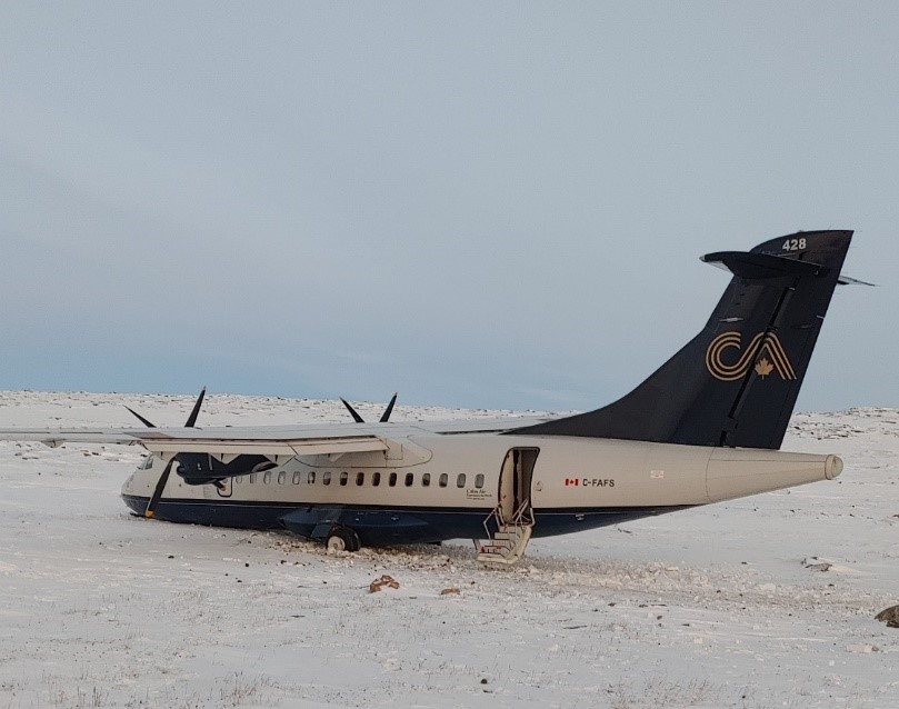
The captain received serious injuries and the 2 other crew members received minor injuries. The aircraft was substantially damaged (Figure 1). The emergency locator transmitter did not activate.
1.2 Injuries to persons
The 3 crew members on board the aircraft were injured (Table 1). The captain was seriously injured. He was examined at the Repulse Bay Health Centre and was later transported to Winnipeg, Manitoba, for further examination. It was determined that he had received serious head injuries. The 2 other crew members sustained minor injuries.
| Degree of injury | Crew | Passengers | Persons not on board the aircraft | Total by injury |
|---|---|---|---|---|
| Fatal | 0 | – | – | 0 |
| Serious | 1 | – | – | 1 |
| Minor | 2 | – | – | 2 |
| Total injured | 3 | – | – | 3 |
1.3 Damage to aircraft
After the aircraft had departed the maintained surface of the runway, it travelled through a windrow of compacted snow, then crossed through a shallow ditch and continued over rough terrain. During the runway excursion, the aircraft sustained damage to the forward fuselage belly area. Additionally, the nose gear collapsed, both main landing gear assemblies were damaged, and the left main landing gear was almost completely severed from its attachment points.
1.4 Other damage
Not applicable.
1.5 Personnel information
| Captain | First officer | |
|---|---|---|
| Pilot licence | Airline transport pilot licence | Airline transport pilot licence |
| Medical expiry date | 31 January 2021 | 30 April 2021 |
| Total flying hours | 21 000 | 16 500 |
| Flight hours on type | 1477 | 1749 |
| Flight hours in the 7 days before the occurrence | 13.4 | 11.7 |
| Flight hours in the 30 days before the occurrence | 13.4 | 17.4 |
| Flight hours in the 90 days before the occurrence | 44.1 | 51.5 |
| Flight hours on type in the 90 days before the occurrence | 44.1 | 51.5 |
| Hours on duty before the occurrence | 7.5 | 7.5 |
| Hours off duty before the work period | 12 | 12 |
1.5.1 Captain
The captain had been employed by Calm Air since February 1999. He had previously been a captain and first officer on the Saab 340 for the company and was promoted to captain on the ATR 42 in April 2014. The captain had successfully completed his recurrent ATR 42 simulator training on 04 September 2020 and crew resource management (CRM) training on 04 February 2020. The captain held the appropriate licence and ratings for the flight in accordance with existing regulations.
1.5.2 First officer
The first officer had been employed by Calm Air since June 1998. He had previously been a first officer on the DHC-6 Twin Otter, Saab-340, and Fairchild-Dornier 328 JET, and became a first officer on the ATR 42 in April 2017. The first officer had completed his recurrent ATR 42 simulator training on 25 June 2020 and his CRM training on 14 May 2020. The first officer held the appropriate licence and ratings for the flight in accordance with existing regulations
1.5.3 Flight attendant
Although there were no passengers on board, the flight carried a flight attendant in the rear passenger cabin. At the time of the occurrence, she was not seated in her normal flight attendant seat; she was seated in a left window seat just aft of the left wing.
1.6 Aircraft information
1.6.1 General
The ATR 42-300 is a pressurized twin-engine turboprop manufactured by Avions de Transport Régional (ATR) and type certified in the transport category.
The occurrence aircraft was manufactured in 1993, and acquired by Calm Air in 2013. It was configured as a cargo/passenger combi aircraft. The forward area of the cabin was a cargo compartment with restraints and was separated from the rear passenger area by a bulkhead. The rear area, aft of the bulkhead, had seats to accommodate 22 passengers plus 2 flight attendants.
| Manufacturer | ATR-GIE Avions de Transport Régional (ATR) (formerly Aerospatiale) |
|---|---|
| Type, model, and registration | ATR 42-300, C-FAFS |
| Year of manufacture | 1993 |
| Serial number | 298 |
| Certificate of airworthiness/flight permit issue date | 26 July 2013 |
| Total airframe time | 44 180 hours |
| Engine type (number of engines) | Pratt & Whitney Canada PW121 (2) |
| Propeller type (number of propellers) | Collins Aerospace (formerly Hamilton Sundstrand) Model 14SF-5 (2) |
| Maximum allowable take-off weight | 37 258 pounds |
| Recommended fuel type(s) | Jet A, Jet A1, Jet B |
| Fuel type used | Jet A |
1.6.2 Propeller system
The ATR 42-300 is powered by 2 Pratt & Whitney Canada PW121 turbo prop engines driving 2 Collins Aerospace (formerly Hamilton Sundstrand) Model 14SF-5 propellers. The 14SF propeller is made of metal and composite materials. It is a constant-speed, fully feathering, and reversible propeller.
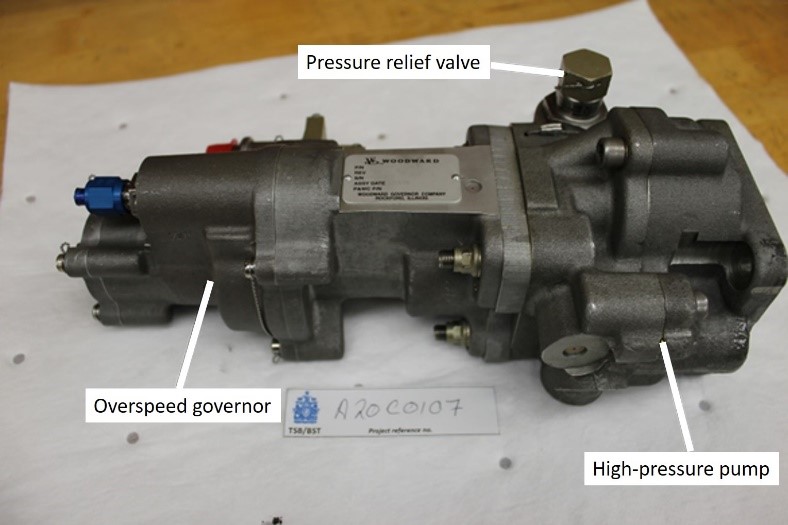
Propeller rpm (Np) and engine rpm (Nh) are controlled hydromechanically via power and condition levers in the cockpit. The mechanical movement of the power and condition levers direct the propeller control unit (PCU) (Figure 2) and hydromechanical unit (HMU)Footnote 7 to regulate propeller rpm.
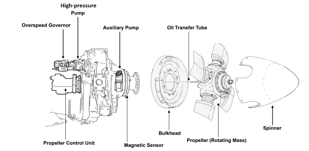
The propeller is controlled by the PCU, which uses high-pressure engine oil to control the blade angle. Engine oil pressure is increased by a high-pressure pump mounted on the propeller reduction gearbox.
There are 3 modes of propeller governing:
- Fuel-governing mode: On the ground and at low aircraft speed, the HMU and electronic engine control maintain the propeller rpm at 70.8% by regulating fuel to the engine.
- Transition mode: The propeller rpm (Np) is within 71% to 77%. Forward movement of the power lever (beyond the flight idle gateFootnote 8) adds more fuel, and the Np increases to 77%, where the condition lever position can start to control Np.
- Propeller-governing mode: The Np is greater than 77% and the power levers are beyond the flight idle gate. Propeller speed is controlled by the PCU and input from the condition lever.
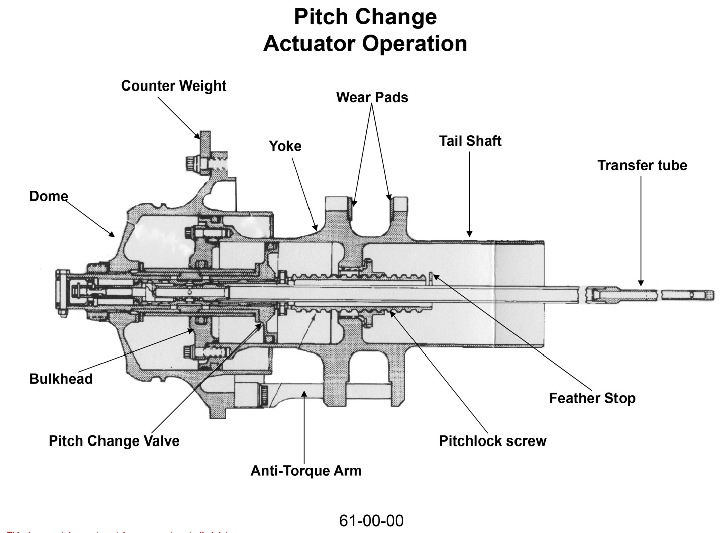
The propeller incorporates several safety devices, one of which is a pitch-lock mechanism. The pitch-lock mechanism is located inside the pitch change actuator. The mechanism locks the blade pitch and prevents propeller overspeed in the event that oil pressure to the PCU is lost. If oil pressure is lost while the propeller is in a positive blade angle, centrifugal and aerodynamic forces will attempt to drive the propeller blades to a flat pitch (approximately 0°). If this were to happen, the propeller would overspeed and produce high drag.
The pitch lock is engaged when the pitch-lock screw makes contact with the pitch-change valve on the bulkhead (Figure 3). The pitch of the pitch-lock screw thread combined with the friction between the pitch-lock screw and pitch-change valve is such that the acme thread of the pitch-lock screw cannot be back driven. This pitch-lock feature limits overspeed to approximately 2% at any positive blade angle as long as the operating condition and engine power do not change. If the pitch-lock is engaged, the flight crew cannot achieve reverse thrust.
When the power levers are in the ground-idle range and the aircraft is on the ground, there are ‘’LO PITCH” lights that illuminate when propeller blade angles are lower than the normal flight idle blade angle. These lights will not illuminate if the propellers are in a pitch-lock condition and are in the normal flight blade angle range. Other than subtle cues, there is no caution or warning light in the cockpit to indicate that the pitch lock is engaged; there is no pitch lock warning on the crew alerting panel (CAP) or on the master warning system.
1.6.3 Propeller maintenance
The Collins Aerospace 14SF-5 propellers installed on Calm Air’s ATR 42 aircraft are maintained in accordance with the Airworthiness Limitations section of the Hamilton Sundstrand Maintenance Manual, Footnote 9 which states the major inspection intervals for various parts of the propeller.
The inspection interval for the blade and pin assemblies, as well as the propeller hub (within which the pitch change actuator is mounted) is 10 500 flight hours or 7 years from the date of installation. The inspection interval for the propeller outer and inner bearing races and the actuator assembly is 10 500 flight hours.Footnote 10
In addition, a critical part inspection (CPI) is required for the actuator assembly, oil transfer tube and retainer, and PCU. The CPI interval for the actuator assembly is 10 500 flight hours. The interval for the initial inspection of the oil transfer tube and retainer and the PCU is 6000 flight hours or 3 years. The CPI must be repeated at intervals of 10 500 flight hours.Footnote 11 These CPIs satisfy the requirements of the U.S. Federal Aviation Administration’s Airworthiness Directive (AD) 96-25-20Footnote 12 as an alternate method of compliance.
A review of Calm Air’s maintenance records indicated that the left propeller’s components had been inspected in accordance with AD 96-25-20 on 18 November 2018 and were installed on the occurrence aircraft on 11 November 2019. The CPI had not revealed any defects that may have caused the propeller components to malfunction.
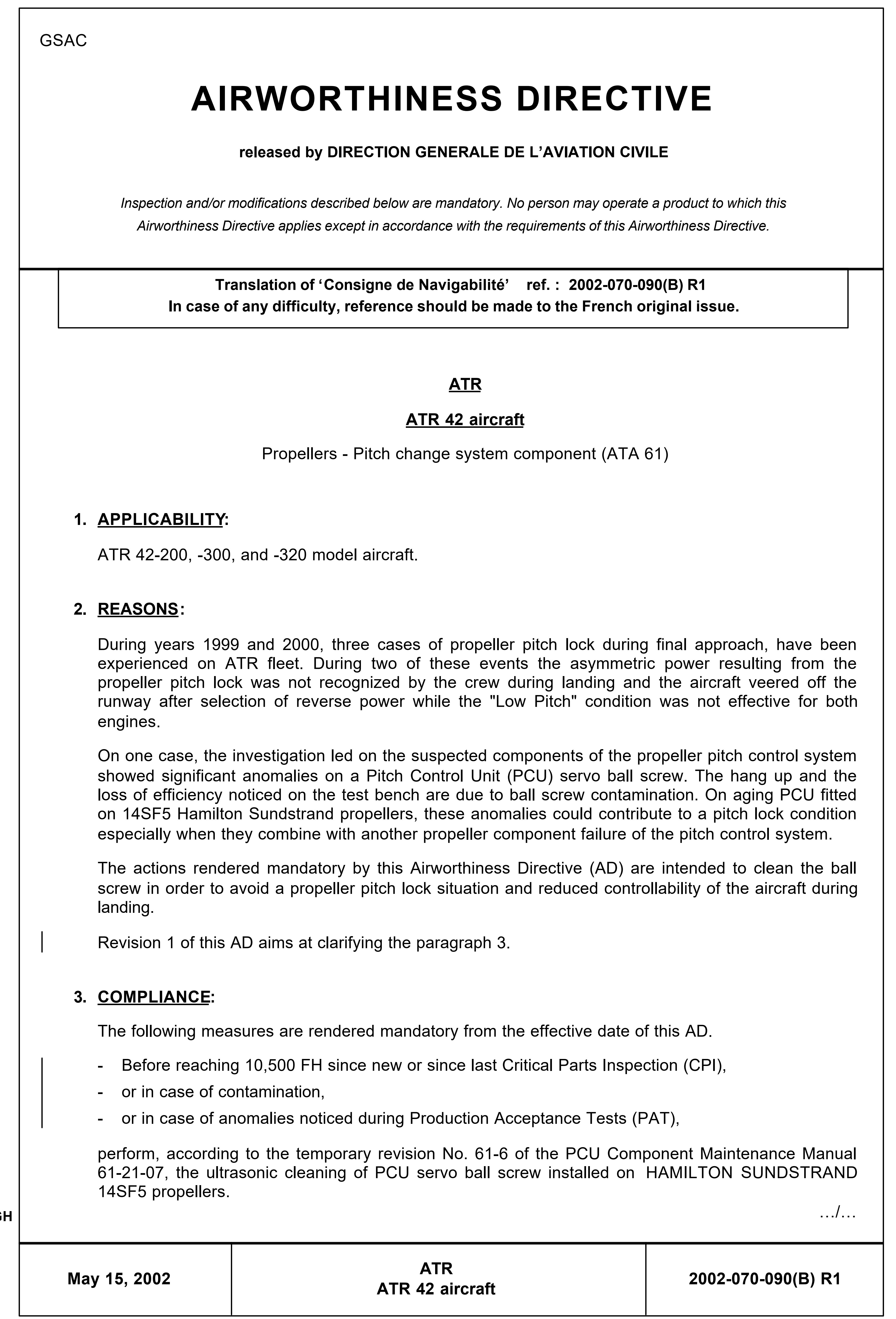
On 23 January 2002, the French Direction générale de l’aviation civile issued AD 2002-070-091(B) related to the pressure relief valve.Footnote 13 The investigation determined that all inspections mentioned in this AD were either complied with or not applicable because of the part number.
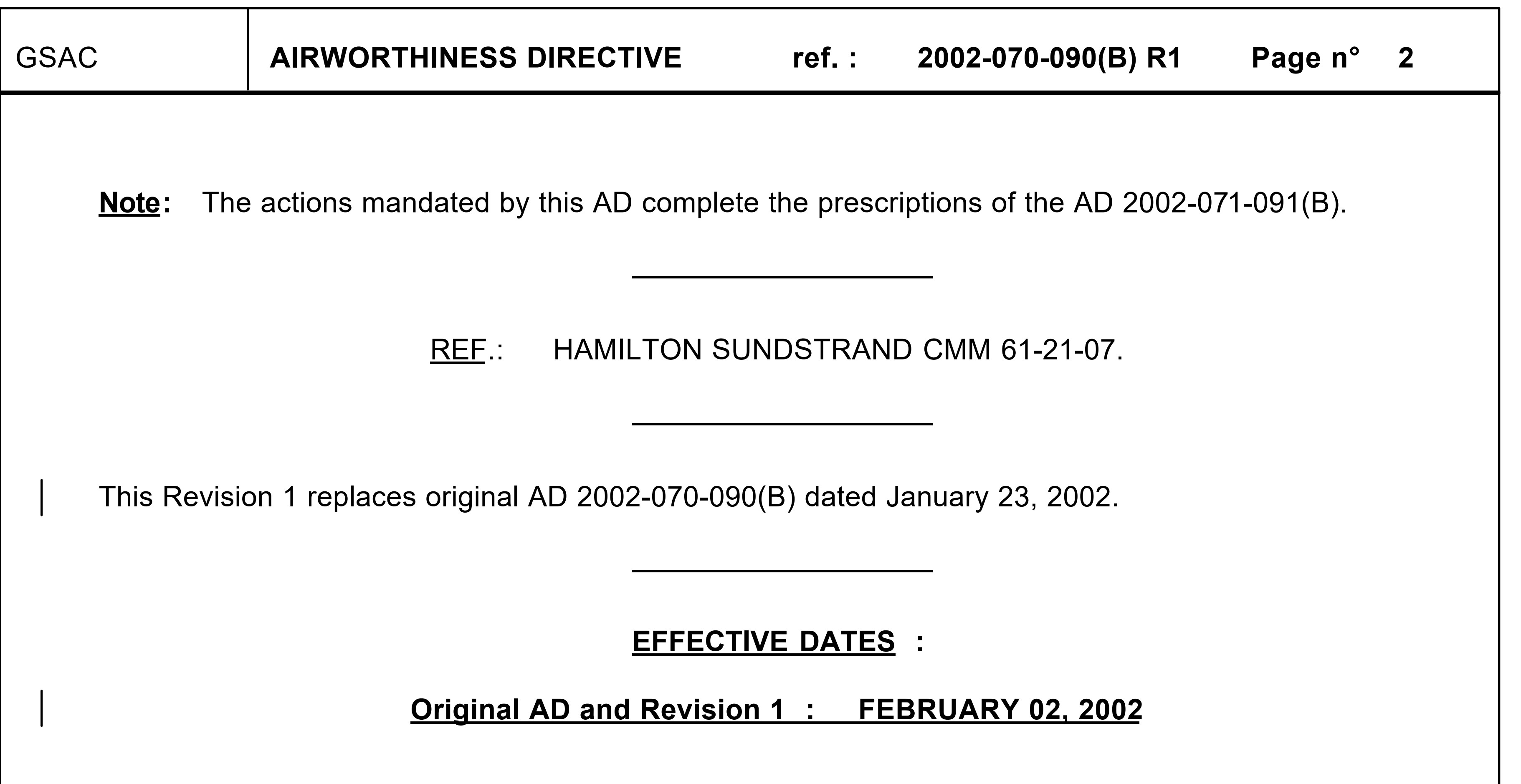
There have been 4 other occurrences involving ATR 42 series aircraft in which flight crews did not identify pitch-locked propellers that resulted in control difficulties and runway excursions when reverse thrust was selected (Appendix A). On 15 May 2002, the French Direction générale de l'aviation civile issued Airworthiness Directive 2002-070-090(B) R1 (Appendix B) to address the issue.Footnote 14
1.6.4 Cockpit engine and propeller indications
The engine and propeller indications in ATR 42 series aircraft are displayed in both analogue and digital formats. The dials indicate:
- Engine torque in %
- Propeller rpm in % (Figure 4)
- Engine rpm (Nh) in %
- Engine oil pressure in psi (note: not propeller oil pressure)
- Engine oil temperature in °C

The normal rpm range (between 70.8% and 100%) is indicated by a green arc on the gauge.
1.7 Meteorological information
1.7.1 General
Both CYUT and CYRT have community aerodrome radio stations, which provide weather information that is contained in aerodrome routine meteorological reports (METARs).
Several types of weather forecasts are available for flight planning and navigation purposes, such as aerodrome forecasts (TAFs) and graphic area forecasts (GFAs). The information contained in these forecasts is based on weather information observed and analyzed by Environment and Climate Change Canada and provided to the aviation industry by NAV CANADA.
1.7.2 Departure weather
Prior to departing CYRT, the flight crew received the following weather information.
The TAF for CYUT issued at 0839 and valid for the period between 0900 and 1700 forecasted the following:
- From 1100:
- Winds from 360° true (T) at 6 knots
- Visibility greater than 6 statute miles (SM)
- Scattered clouds at 2000 feet above ground level (AGL) and broken ceiling at 20 000 feet AGL
- Temporarily from 1100 to 1700:
- Visibility 3 SM in ice crystals and mist
- Few clouds at 600 feet AGL and a broken ceiling at 2000 feet AGL
- With a 30% probability from 1100 to 1700:
- Visibility 2 ½ SM in ice crystals and mist
The METAR issued at 1100 for CYUT indicated the following:
- Winds from 030°T at 3 knots
- Visibility 15 SM
- Few clouds at 9400 feet AGL, with a broken ceiling at 22 000 feet AGL
- Temperature −23 °C, dew point −26 °C
- Altimeter setting of 29.66 inches of mercury
The TAF for CYBK, the alternate airport listed on the IFR flight plan, issued at 0541 and valid from 0600 to 1800 forecasted the following:
- From 0600 to 1800:
- Winds from 010°T at 8 knots, gusting to 28 knots
- Visibility greater than 6 SM in light snow
- Overcast ceiling at 3000 feet AGL
- Temporarily from 0600 to 1800:
- Visibility 4SM in light snow and blowing snow
- Overcast ceiling at 2000 feet AGL
1.7.3 Arrival weather
The reported weather conditions for CYUT taken at 1334 (approximately 8 minutes after the occurrence) were:
- Winds from 020°T at 6 knots
- Visibility 15 SM
- Scattered clouds at 15 000 feet AGL, broken ceiling at 24 000 feet AGL
- Temperature −23 °C, dew point −26 °C
- Altimeter setting of 29.65 inches of mercury
1.8 Aids to navigation
Not applicable.
1.9 Communications
Not applicable.
1.10 Aerodrome information
1.10.1 General
Naujaat Airport (CYUT) is located approximately ½ km east of the village of Naujaat, Nunavut. It has a single gravel-surface runway, Runway 16/34, that measures 3400 feet long by 100 feet wide. The orientations of runways 16 and 34 are, respectively, 161°T and 341°T. The landing distance available is 3400 feet. Runway 34 has an upslope grade of 1.08%.
CYUT is available for use 24 hours a day, 7 days a week, supporting both day and night, VFR (visual flight rules) and IFR operations. The community aerodrome radio station at CYUT provides local weather, traffic, and other information related to the airport during scheduled hours (Monday to Friday, 0645 to 1715) and is also available after hours on a call-out basis. At the time of the occurrence, the CYUT community aerodrome radio station was operational and had a staff person on duty.
1.10.2 Runway surface conditions
The runway surface conditions for CYUT reported at 1158 on 26 November 2020 described the condition of Runway 16/34 as 100% compacted snow-gravel mixture, with remarks indicating that the conditions of both the taxiway and the airport apron were 100% compacted snow.
For Runway 13/31 at CYRT, the reported runway surface condition at 1151 was 90% frost, 10% compacted snow patches and sand. The Canadian Runway Friction Index value was 0.26 at −11 °C.
1.11 Flight recorders
The aircraft was equipped with a Fairchild F1000 flight data recorder (FDR), which can record over 25 hours of flight data on solid-state memory, and an L3 Harris FA2100 cockpit voice recorder (CVR). The L3 Harris FA2100 CVR can record 2 hours on the standard 4 channels (pilot, co-pilot, spare, and cockpit area microphone). The cockpit area microphone channel is recorded at 16 kHz (high quality), whereas the others are recorded at 8 kHz (standard quality).
Both the FDR and the CVR were recovered from the aircraft and sent to the TSB Engineering Laboratory for further analysis.
1.12 Wreckage and impact information
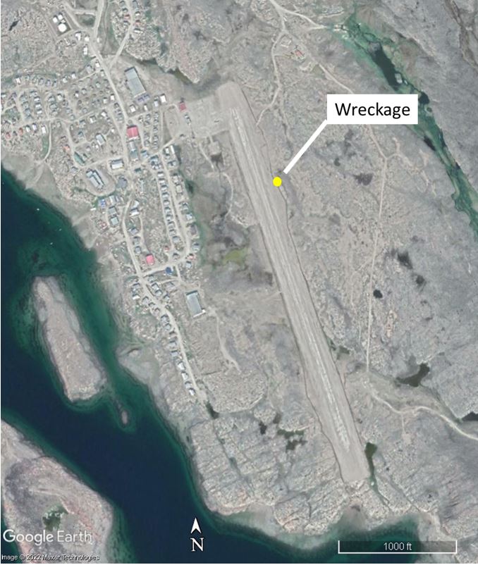
The aircraft came to rest approximately 2500 feet from the threshold of Runway 34 on the unprepared adjacent area to the east (Figure 5). Its location was approximately 108 feet east of the runway edge.
1.13 Medical and pathological information
The captain’s safety belt buckle released during the runway excursion. As a result, the captain was thrown forward by deceleration forces and struck his head on the forward upper cockpit area. He sustained serious head injuries. Consequently, his Transport Canada medical certificate was suspended until such time that it can be concluded that he has not suffered permanent injury.
The first officer’s safety belt remained secure, and he sustained only minor injuries (bruises) to his legs and torso. It could not be determined whether the flight attendant’s lap strap was secure at the time of the runway excursion. She sustained minor injuries.
1.14 Fire
There was no post-impact fire.
1.15 Survival aspects
While the aircraft was traversing the rough terrain adjacent to the runway, some cargo was released from the restraints and partially blocked the access aisle to the cockpit. This unsecured cargo did not prevent the flight crew from exiting the aircraft.
1.16 Tests and research
1.16.1 TSB laboratory reports
The TSB completed the following laboratory reports in support of this investigation:
- LP170/2020 – FDR/QAR Download and Analysis
- LP171/2020 – CVR Download and Analysis
- LP197/2020 – NVM Data Recovery
- LP001/2021 – ATR-42-300 Seat Belt Analysis
- LP002/2021 – Propeller System Examination
1.16.2 Propeller pitch analysis
An analysis of the FDR revealed that the left propeller had entered a pitch-lock condition at the same time the flight crew observed the unstable propeller indication. The propeller pitch had locked at an approximate blade angle of 22.5°.
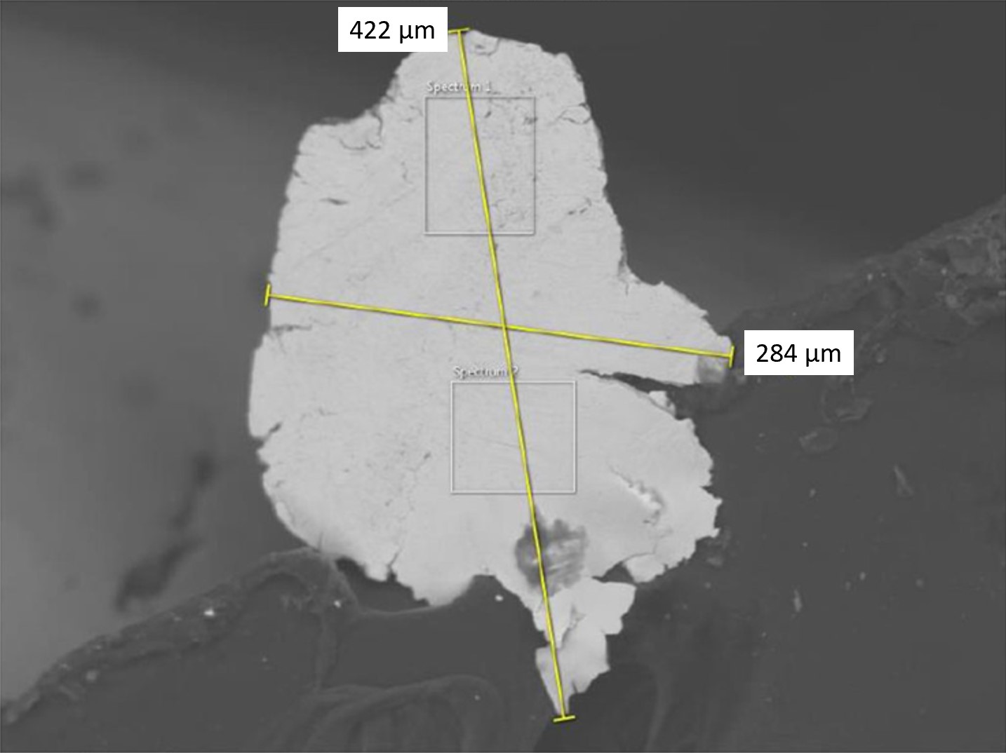
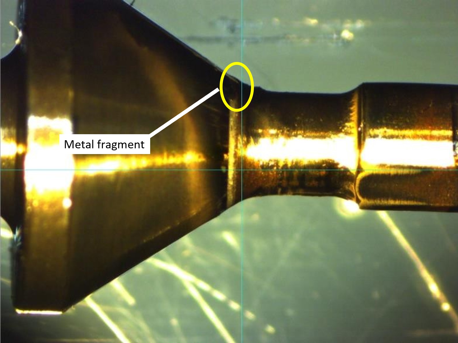
A tear-down inspection of the left PCU revealed that it did not meet certification criteria and was slow to function at normal operating temperatures. More detailed component testing of the propeller’s high-pressure oil pump (Figure 6) revealed that the pump’s pressure relief valve had failed and was not allowing adequate oil pressure to build up in the system.
A metal fragment composed of a low-grade iron substance (Figure 7) was discovered stuck to the sealing surface of the pump’s pressure relief valve (Figure 8), which prevented the pressure relief valve from sealing. The origin of the metal fragment could not be determined; however, the composition of the metal contaminant was not consistent with any parts tested. Given the size of the metal fragment, it should have been trapped by the engine oil filter.
The propeller entered the pitch-lock condition because of the degraded pressure output from the high-pressure pump. The tear-down inspection did not reveal any other pre-existing defects or anomalies that could have caused the left propeller to enter a pitch locked condition.
1.16.3 Safety belts
The safety belt system for each pilot seat was a 4-point restraint system, consisting of a lap strap, shoulder harness, and a rotary release buckle.
Bruises on the captain’s shoulders and abdomen indicate that his lap strap and shoulder harness had initially transferred deceleration forces to his body. However, at some point during the runway excursion, his safety belt system released and his head struck the forward cockpit area.
The TSB laboratory completed a detailed visual inspection of both the captain’s and the first officer’s safety belt systems and included inspecting the fabric condition of the belts and the general condition of the hardware. The functionality of the rotary release buckles was also inspected. No defects were noted.
Upon completion of the visual and rotary release inspections, the TSB laboratory tested the strength of the webbing and the release latch, and the latching effectiveness of both pilot seat safety belt systems by conducting a tensile test. The captain’s 2 lap strap sections and the rotary release mechanism were installed into the tensile tester. The lap strap sections were then pulled to verify conformance with the regulatory specification,Footnote 15 which is 3000 pounds force. There was no premature release of the captain’s rotary mechanism during tensile testing, but the buckle failed internally and both sections of the lap strap disengaged simultaneously at approximately 2937 pounds force. The testing was halted at this point due to the failure of the buckle.
The regulatory specification refers to the entire 4-point harness system being installed in a test rig as a complete assembly. However, the testing that was performed at the TSB Engineering Laboratory used a single-axis tensile tester using 2 grips; therefore, only 2 legs of the 4-point system could be tested at any given time. Although it appears as though the buckle failed the test, for the purposes of this investigation, it demonstrated that the lap straps could withstand significant force before being released.
The inspection and testing did not identify any pre-existing defects or anomalies that could have contributed to an uncommanded release of the captain’s safety belt system during the runway excursion. The cause of the uncommanded safety belt release could not be determined.
1.17 Organizational and management information
1.17.1 General
Calm Air operates in accordance with Subpart 705 (Airline Operations) of the Canadian Aviation Regulations (CARs). It has a fleet of ATR 42 and ATR 72 aircraft in northern Manitoba and the central Arctic.
The company operates under a Type B operational control system, which is a Co-Authority Dispatch System.Footnote 16 Before each flight, dispatchers review weather, NOTAMs, and aircraft performance from a computer-based application, known as NAVBLUE, which generates the operational flight plan (OFP). The flight crew then review the OFP and confirm that the information is correct and that the flight can be conducted safely and in accordance with the CARs and company procedures.
After the flight departs, the dispatchers then perform flight-watch duties using a very high frequency radio and/or a SKYTRAC satellite phone, email, and text messages.
Because Calm Air operates in accordance with Subpart 705 of the CARs, it is required to have a safety management system (SMS). Calm Air’s SMS had recorded 2 previous occurrences involving problems with the propeller; however, neither was related to a pitch-lock condition.
1.17.2 Aircraft flight operations
Instructions and procedures for the operation of company aircraft are contained in Calm Air’s Flight Crew Operations Manual (FCOM),Footnote 17 ATR 42 Aircraft Flight Manual (AFM),Footnote 18 and Standard Operating Procedures (SOPs).Footnote 19
In the event of an emergency or abnormal situation, Calm Air’s SOPs direct flight crews to “assess the situation as a whole, taking into consideration the failures, when fully identified and the flight constraints imposed.” Footnote 20 The SOPs also state,
Any Master Warning (MW) or Master Caution (MC) illumination and associated Single Chime or Continuous Repetitive Chime shall be acknowledged by the PF [pilot flying] call:
“IDENTIFY AND CANCEL”
The PM [pilot monitoring] will then identify the CAP [crew alerting panel] fault and local alert, and then cancel the warning by depressing the associated MW or MC. Footnote 21
The QRH,Footnote 22 which is carried on board the aircraft,Footnote 23 contains an abbreviated version of the FCOM procedures and SOPs. It is a checklist that allows flight crews quick and easy access to critical aircraft information so that they are able to respond appropriately to an emergency or abnormal situation.
1.17.2.1 Low pitch lights procedures
The Normal Procedures section of Calm Air’s SOPs requires that the pilot monitoring call “TWO LOW PITCH” if both LO PITCH lights illuminate on touchdown and states that reverse thrust must not be used if only 1 LO PITCH light illuminates.Footnote 24 In addition, the Abnormal and Procedures Following Failures section of the SOPs states
If both low pitch lights do not illuminate after landing then reverse must not be selected.Footnote 25
A similar caution is also stated in the ATR 42 AFM.Footnote 26 There is no standard call in the SOPs or the ATR 42 AFM for the non-illumination of a low pitch light upon touchdown.
The FCOM elaborates further by stating the following:
CAUTION
If a thrust dissymmetry occurs or if one LO PITCH light is not ON, the use of any reverser is prohibited.
In this case the propeller pitch change mechanism is probably locked at a positive blade angle, resulting in a positive thrust for any PL [power lever] position.
Applying any reverser could result in an increased positive thrust and therefore in a difficulty to control lateral asymmetry.Footnote 27
The normal landing procedures in both the FCOMFootnote 28 and QRHFootnote 29 contain a table with calls and reverse actions based on the LO PITCH lights’ illumination status on landing (Table 4).
| ENG | LO PITCH | ANNOUNCE | REVERSE |
|---|---|---|---|
| 2 ENG | 2 | 2 LOW PITCH | NORMAL USE |
| 1 | NO REVERSE | NO REVERSE | |
| 0 | |||
| 1 ENG | 1 | 1 LOW PITCH | USE WITH CARE |
1.17.3 Quick Reference Handbook design features
The QRH contains procedures that may need to be referred to quickly or frequently by a knowledgeable user during aircraft operation, including emergency and abnormal procedures. It also provides strategies to address the prevailing conditions. While the flight crew may refer to information and the expanded abnormal and emergency procedures contained in the AFM, SOPs, or FCOM for possible additional guidance, conditions permitting, the QRH is a stand-alone document.
The way the QRH is designed and developed is critical to ensuring that pilots respond appropriately to various situations. The QRH provides strategies to address specific failures so as to minimize their operational impact on aircraft systems and performance. It aims to ensure that the response to an emergency or abnormal situation is as organized and all-encompassing as possible at a time when the flight crew members’ cognitive load can impair their performance. To fulfil this aim, the QRH must use clear and unambiguous layout ergonomics. Content must be able to support pilots in correctly identifying an abnormal or emergency situation as well as the associated preconditions and conditional steps to address the situation while avoiding the omission of an action or the use of irrelevant or inadvertent actions.
1.17.3.1 Quick Reference Handbook
The QRH carried in the cockpit on the occurrence flight was revision 1.0, dated January 2018. The following features of the format and layout were noted:
- The first page of text after the cover page lists the QRH sections in the order they appear: OEB (Operations Engineering Bulletins), GEN (General Information), LIM (Limitations), EMR (Emergency Procedures), ABN (Abnormal Procedures), NOR (Normal Procedures), PER (Performance [Operational] Data).
- A coloured divider identifies 4 of the 7 sections: yellow for Operations Engineering Bulletins, red for Emergency Procedures, orange for Abnormal Procedures, and green for Normal Procedures.
- At the end of the General Information section, there is a list of the procedures found in the Emergency Procedures and Abnormal Procedures sections. These are organized by following the Air Transport Association (ATA) numbering system as much as practical, not by failure, and no page numbers are listed. This lack of information does not lead to an expeditious finding of a given procedure in the event of an emergency.
- At the beginning of the Emergency Procedures and Abnormal Procedures sections the procedures each section contained are listed, albeit without page numbers. The Abnormal Procedures section is organized sequentially by ATA code, each under a heading of aircraft system (e.g., air conditioning, flight controls, power plant, etc.); the Emergency Procedures section is similarly organized except without aircraft system headings.
- There is no specific section in the QRH pertaining to propeller operation or any related abnormal operation. Under the heading of Power Plant in the Abnormal Procedures section are procedures pertaining to propeller operations.
1.17.3.2 Abnormal procedures in the Quick Reference Handbook
There are 3 abnormal-situation checklist items in the QRH that are related to the propeller system in flight: “LO PITCH IN FLIGHT” (code A70.11), Footnote 30 “ABNORMAL ENG [engine] PARAMETERS IN FLIGHT” (code A70.13), Footnote 31 and “PROP 1(2) OVER LIMIT” (code A70.19). Footnote 32
The purpose of these procedures is to help the flight crew isolate the affected engine and then shut it down. These 3 procedures are located in the Abnormal Procedures section, under Following Procedures: Power Plant. There is no specific procedure for a pitch-lock condition, nor is there a separate QRH section for propeller abnormal operations.
All 3 of these abnormal procedures direct the flight crew to shut down the affected engine and apply the “SINGLE ENG [engine] OPERATION” procedure (code A70.12).
1.18 Additional information
1.18.1 Arctic flight operations
Aircraft engaged in arctic flight operations are subject to particular conditions that can affect flight crew decision making to a greater extent than in flight operations conducted further south. These conditions include the following:
- extreme cold weather
- slippery runwaysFootnote 33
- only a single runway at most airports, which may lead to crosswind conditions on takeoff and landing
- limited number of aerodromes, which results in great distances to alternate airportsFootnote 34 and maintenance and repair facilities
1.18.2 Crew communications
Crew resource management (CRM) is “the effective utilization of all resources including crew members, aircraft systems, supporting facilities and persons to achieve safe and efficient operations. The objective of CRM is to enhance communication, interaction, human factors and management skills of the crew members concerned.” Footnote 35 CRM training required by Transport Canada includes effective crew communications, threat and error management, and human factor issues relating to aviation. Footnote 36 One particularly important method of gathering information is through effective crew communications. Effective communication is defined as the ability to clearly convey an intended message. Before the approach into CYUT, there was very little communication between the flight crew members about the abnormal propeller rpm indications and possible options.
2.0 Analysis
This analysis will focus on the following:
- The multiple component failures of the propeller control system, one of which resulted in a propeller pitch-lock condition;
- The flight crew’s actions and decision making in response to the propeller pitch-lock condition;
- The usability of the Quick Reference Handbook (QRH) checklist; and
- Survivability with respect to the uncommanded release of the captain’s safety belt.
2.1 Propeller control unit failure
The tear-down inspection of the left propeller control unit (PCU) revealed that it did not meet certification criteria and was slow to function at normal operating temperatures. Testing of the propeller’s high-pressure oil pump revealed that its pressure relief valve was not allowing adequate oil pressure to build up in the system.
Metal contamination from an undetermined source was found in the high-pressure pump’s pressure relief valve and was preventing the valve from sealing. The impeded seal decreased the pressure output from the high-pressure pump, and decreased the ability of the PCU to control the propeller pitch.
This decreased pressure output occurred during the cruise portion of the occurrence flight, around the same time the flight crew observed the unstable propeller indication. When the decreased pressure output occurred, in order to prevent the aerodynamic and centrifugal pressure from driving the propeller blades into fine pitch (and cause an overspeed condition), the propeller pitch-lock mechanism activated and locked the propeller blades in approximately 22.5° of pitch. This pitch-lock condition was, however, unknown to the flight crew.
Finding as to causes and contributing factors
A contaminant inside the left propeller’s high-pressure pump caused its pressure relief valve to fail. As a result, the propeller entered a pitch-lock condition and remained in that condition until the aircraft landed.
The Calm Air Standard Operating Procedures (SOPs) require the pilot monitoring to make a call if both LO PITCH lights illuminate on touchdown and specify that reverse thrust is not permitted if only 1 light illuminates. There is no requirement for a standard call in the SOPs or the ATR 42 Aircraft Flight Manual (AFM) for the non-illumination of a low pitch light during landing. However, the AFM, the QRH, and the Flight Crew Operations Manual (FCOM) all state that if both LO PITCH lights do not illuminate after landing, reverse thrust must not be selected because the pitch change mechanism is probably locked at a positive blade angle.
On touchdown, 750 feet past the threshold, the pilot flying immediately selected reverse thrust, possibly due to the relatively short runway length; however, only the right propeller went into reverse. Almost simultaneously with the selection of reverse thrust, only the “LO PITCH” light for the No. 2 engine illuminated. The pilot monitoring did not have the time to identify the status of the LO PITCH lights and to make the “TWO LOW PITCH” callout before reverse was selected. The flight crew was unaware that the left propeller was in a pitch-lock condition and that reverse thrust was unavailable on the left side.
Findings as to causes and contributing factors
Immediately on touchdown, reverse thrust was selected by the pilot flying without confirmation that both LO PITCH lights had illuminated. With the left propeller in a pitch-lock condition, the selection of reverse thrust resulted in the aircraft entering an asymmetric thrust state.
Due to the asymmetric thrust, directional control of the aircraft could not be maintained. As a result the aircraft exited the landing surface of the runway, travelled across rough terrain adjacent to the runway, and was substantially damaged.
2.2 Crew communications
When the flight crew first noticed the abnormal propeller indications, they briefly discussed the situation, but they did not consult the QRH to find a solution to their situation, or take any other procedural action. The captain considered his options (i.e., return to Rankin Inlet Airport, shut down the left engine, or both); however, he did not specifically discuss these options with the first officer. This meant that the flight crew did not fully assess their situation as a team, which may have prevented them from identifying the nature of the malfunction that they were experiencing. This was not in accordance with CRM best practices.
Finding as to risk
If flight crews do not assess abnormal situations as a team, there is a risk that they will not identify the nature of the abnormal situation and determine the most appropriate action to take.
2.3 Quick Reference Handbook
The QRH does not contain a specific abnormal or emergency procedure explaining how flight crews can identify and manage a propeller pitch-lock condition in flight.
The only procedure in the QRH that could be presumed to address a pitch-lock condition is the “ABNORMAL ENG [engine] PARAMETERS IN FLIGHT” (code A70.13), which is found in the Abnormal Procedures section of the QRH. The purpose of this procedure is to help the flight crew isolate the affected engine and then shut it down. In this occurrence, the flight crew briefly discussed the situation and made various attempts to troubleshoot and identify the problem, but they did not consult the QRH.
During the occurrence flight, the propeller rpm fluctuated but remained within limitations and the engine parameters were normal. In fact, the captain believed that the propeller rpm fluctuations were related to a pre-flight maintenance activity. Because there was no clear indication of a pitch-lock condition, the flight crew were not aware of what the safest course of action was to resolve the issue.
Finding as to causes and contributing factors
Because there is no indication in the cockpit of a pitch-lock condition in flight, the flight crew were not aware that the propeller had entered a pitch-lock condition, and they continued the flight to Naujaat Airport (CYUT), Nunavut, without discussing any options.
Given the layout of the QRH, flight crews need to be familiar with the QRH and type of malfunction in order to quickly locate the applicable procedures. While the abnormal and emergency sections could be identified using the coloured dividers, it would still take time for a flight crew to leaf through sections to locate the procedure. There are no page numbers in the table of contents to assist the flight crew; the codes associated with the procedures take time to identify in the table of contents, and must then be memorized while the flight crew are leafing through the section until the desired code is found. The layout and design of the QRH makes it difficult for a flight crew to quickly and efficiently find the desired procedure in an emergency.
Finding as to risk
If the layout and design of a QRH make it difficult for flight crews to find a procedure to address a malfunction, they may not take the appropriate actions quickly or efficiently, which may lead to an unsafe aircraft state.
2.4 Survivability
The captain’s safety belt buckle released without input from the captain at some point during the runway excursion. The cause of the uncommanded safety belt release could not be determined.
Finding as to causes and contributing factors
For undetermined reasons, the captain’s safety belt buckle released during the runway excursion and the captain’s head struck the forward upper area of the cockpit, resulting in serious head injuries.
3.0 Findings
3.1 Findings as to causes and contributing factors
These are conditions, acts or safety deficiencies that were found to have caused or contributed to this occurrence.
- A contaminant inside the left propeller’s high-pressure pump caused its pressure relief valve to fail. As a result, the propeller entered a pitch-lock condition and remained in that condition until the aircraft landed.
- Because there is no indication in the cockpit of a pitch-lock condition in flight, the flight crew were not aware that the propeller had entered a pitch-lock condition, and they continued the flight to Naujaat Airport (CYUT), Nunavut, without discussing any options.
- Immediately on touchdown, reverse thrust was selected by the pilot flying without confirmation that both LO PITCH lights had illuminated. With the left propeller in a pitch-lock condition, the selection of reverse thrust resulted in the aircraft entering an asymmetric thrust state.
- Due to the asymmetric thrust, directional control of the aircraft could not be maintained. As a result the aircraft exited the landing surface of the runway, travelled across rough terrain adjacent to the runway, and was substantially damaged.
- For undetermined reasons, the captain’s safety belt buckle released during the runway excursion and the captain’s head struck the forward upper area of the cockpit, resulting in serious head injuries.
3.2 Findings as to risk
These are conditions, unsafe acts or safety deficiencies that were found not to be a factor in this occurrence but could have adverse consequences in future occurrences.
- If flight crews do not assess abnormal situations as a team, there is a risk that they will not identify the nature of the abnormal situation and determine the most appropriate action to take.
- If the layout and design of a Quick Reference Handbook make it difficult for flight crews to find a procedure to address a malfunction, they may not take the appropriate actions quickly or efficiently, which may lead to an unsafe aircraft state.
4.0 Safety action
4.1 Safety action taken
4.1.1 Calm Air International LP
On 09 December 2020, the operator issued Flight Operations Bulletin 2020-07, which describes a condition known as “pitch lock.” It further describes:
- possible causes for this condition;
- how to identify it; and
- what action to take if this condition is suspected.
In February 2021, the operator introduced to its ATR 42 recurrent simulator training scenarios in which the propeller enters a pitch-lock condition.
This report concludes the Transportation Safety Board of Canada’s investigation into this occurrence. The Board authorized the release of this report on . It was officially released on .
Appendices
Appendix A – Previous ATR 42 pitch-lock accidents
| Date | Aircraft model (serial number) | Engine model | Location | Event description | Technical analysis |
|---|---|---|---|---|---|
| 1999-10-24 | ATR 42-320 (284) | PW121 | Apartadó/Antonio Roldán Betancur Airport, Colombia |
|
|
| 2000-08-01 | ATR 42-320 (169) | PW121 | Athens International Airport, Greece |
|
|
| 2007-07-16 | ATR 42-300 (unknown) | PW120 | São Paulo/Congonhas Airport, Brazil |
|
|
| 2009-05-30 | ATR 72-202 (316) | PW124B | Unknown |
|
|
Source of information: Avions de Transport Régional
Appendix B – Airworthiness Directive: ATR 42 aircraft – Propellers – Pitch change system component (ATA 61)
Source: Direction générale de l’aviation civile, Airworthiness Directive AD 2002-070-090(B) R1: ATR 42 aircraft – Propellers – Pitch change system component (ATA 61) (issued 15 May 2002).