Main rotor blade failure and collision with terrain
E & B Helicopters Ltd.
Bell 206B (helicopter), C-GEBY
Campbell River, British Columbia
The Transportation Safety Board of Canada (TSB) investigated this occurrence for the purpose of advancing transportation safety. It is not the function of the Board to assign fault or determine civil or criminal liability. This report is not created for use in the context of legal, disciplinary or other proceedings. See Ownership and use of content. Masculine pronouns and position titles may be used to signify all genders to comply with the Canadian Transportation Accident Investigation and Safety Board Act (S.C. 1989, c. 3).
Executive Summary
On 24 September 2019, the E & B Helicopters Ltd. Bell 206B helicopter (registration C-GEBY, serial number 3375) was conducting a visual flight rules flight from the operator's base at Campbell River (E & B Heli) Heliport (CCR6) in Campbell River, British Columbia, to Moat Lake, British Columbia, with only the pilot on board.
Shortly after departure, while flying southeast along the coastline, the helicopter briefly levelled off at 615 feet above sea level, then began a descent. When the helicopter was at 417 feet above sea level, it entered a right-hand climbing turn toward land and, following the turn, it began to descend again. During this descent, at 1103 Pacific Daylight Time, control of the helicopter was lost when it was about 200 feet above ground level and the helicopter fell to the ground, striking a building and 2 vehicles. The pilot was fatally injured. No one on the ground was injured. The helicopter was destroyed by the impact forces and a post-impact fire.
The investigation found that an engine power anomaly likely occurred while the helicopter was in cruise flight and, as a result, the pilot reversed course and entered a descent consistent with an autorotation. Following the occurrence, a visual and microscopic examination of the main rotor blades revealed several indications of structural failure in flight. At some point during the flight, both main rotor blades became deformed. Although indications of fatigue were present post-occurrence on a small portion of the trailing edge of one of the main rotor blades, the extent to which this fatigue contributed to the deformation could not be determined. The investigation also found that in the last moments of the flight, likely as a result of the deformed blades, the main rotor rpm decreased to a point that could not sustain autorotational flight, and the helicopter fell vertically and impacted the ground.
The investigation also revealed that the engine fuel system did not have the appropriate accumulators and double check valve for the Bell 206 helicopter. During the installation of the engine, the company maintenance control system was ineffective at ensuring that the engine installation complied with the manufacturer’s recommendations, including having the correct accumulator and double check valve configuration for the Bell 206. If maintenance procedures do not include a thorough review of all related instructions and bulletins, there is a risk that an aircraft will be released into service in a non-airworthy configuration.
The investigation examined the air operator’s safety culture. Safety culture within a company can be summarized as “how we do things around here.” The pilot was the company’s owner, accountable executive, and operations manager, and direction on how the maintenance department was to respond to a partial loss of engine power that occurred a week before the occurrence came from him. The investigation revealed that many operational and maintenance-related decisions were being made based on a single opinion, rather than a process of validation by a hierarchy of independent and skilled supervisors. In addition, several opportunities to improve the safety of the flight had been missed. If company management routinely deviates from regulatory requirements, there is an increased risk that an unsupportive safety culture will develop, affecting the entire organization.
The investigation examined the certification process of composite main rotor blades. A structural fatigue test, completed as part of the primary structural element threat assessment, is intended to ensure the continuing airworthiness of a structural component, the failure of which could be catastrophic. A dynamic load assessment helps determine the maximum damage size to be introduced into the structural fatigue test specimen. The investigation determined that no dynamic assessment was carried out for the certification of the model of Van Horn composite blades installed on the occurrence helicopter. If data from a dynamic assessment is not available, the fatigue test may not discover structural responses associated with this damage. If a structural fatigue test does not include quantitative assessments and simulated damage that is of probable sizes and at critical locations as determined from a dynamic load assessment, the resulting airworthiness limitations may not be adequate to prevent failures or excessive structural deformations.
The Van Horn composite blades are certificated on the basis of the “no-growth” method. This method is used to show that “the structure, with damage present, is able to withstand repeated loads of variable magnitude without detectable damage growth within a specified replacement time.”Footnote 1 However, Van Horn’s quality assurance process has no established inspection for internal defects following production, or criteria for the permissible size of internal defects. Therefore, it is possible that an unknown intrinsic flaw could exist following production that might exceed a predefined damage limit and would affect the structural integrity of the helicopter blades. If helicopter main rotor blade manufacturing processes do not include internal inspections for defects or criteria for permissible defects, there is a risk that defects that affect structural integrity will not be identified.
Finally, the investigation examined Transport Canada’s (TC’s) approach to managing cardiovascular health and hypertension in pilots. Using a variety of different risk calculators and all available medical information about the occurrence pilot, an independent cardiology review was conducted as part of this investigation and determined that the pilot’s actual annual risk for a sudden incapacitating cardiovascular event exceeded 5% per year. This surpasses the 2% threshold set by TC and the 1% threshold cardiologists recommend for single-pilot operations. Post-mortem results confirmed the presence of extensive atherosclerotic coronary artery disease in all 4 major coronary arteries, with significant (>75%) stenosis. This analysis revealed that the pilot possessed many of the key indicators for a high-risk cardiac event. In this occurrence, TC’s civil aviation medical examination to assess pilot fitness did not identify the level of risk presented by the pilot. If TC guidance material and the civil aviation medical examination report do not require a Civil Aviation Medical Examiner (CAME) to perform a global cardiovascular assessment, when appropriate, there is an increased risk that a pilot with high cardiovascular risk factors will be incapacitated while operating an aircraft as a result of a medical event.
The investigation determined that the pilot was not forthcoming with his CAMEs about conditions that were being followed by his family physician. In addition, the pilot’s family physician did not report the pilot’s conditions to TC, which contributed to TC’s incomplete understanding of the pilot’s health. If pilots do not declare all health issues to TC CAMEs and/or if pilots’ family physicians do not report medical conditions that are likely to constitute an aviation hazard, as required, TC may not be able to accurately assess the medical fitness of pilots, resulting in an increased risk that pilots will operate with diagnosed medical conditions that could affect flight safety.
1.0 Factual information
1.1 History of the flight
On 24 September 2019, the E & B Helicopters Ltd. Bell 206B helicopter (registration C-GEBY, serial number 3375) was conducting a visual flight rules flight from the operator's base at Campbell River (E & B Heli) Heliport (CCR6) in Campbell River, British Columbia (BC), to Moat Lake, BC, which is 22 nautical miles south of Campbell River. The pilot was alone on board. The purpose of the flight was to resupply a cabin on Moat Lake.
The pilot conducted a pre-flight inspection of the helicopter at 1046.Footnote 2 This was captured on closed-circuit television (CCTV) video and showed the pilot looking at the underside of the main rotor blades from the ground and inspecting the tail rotor blades. Camp supplies were loaded into the helicopter 4 minutes later. The helicopter departed CCR6 at 1100.
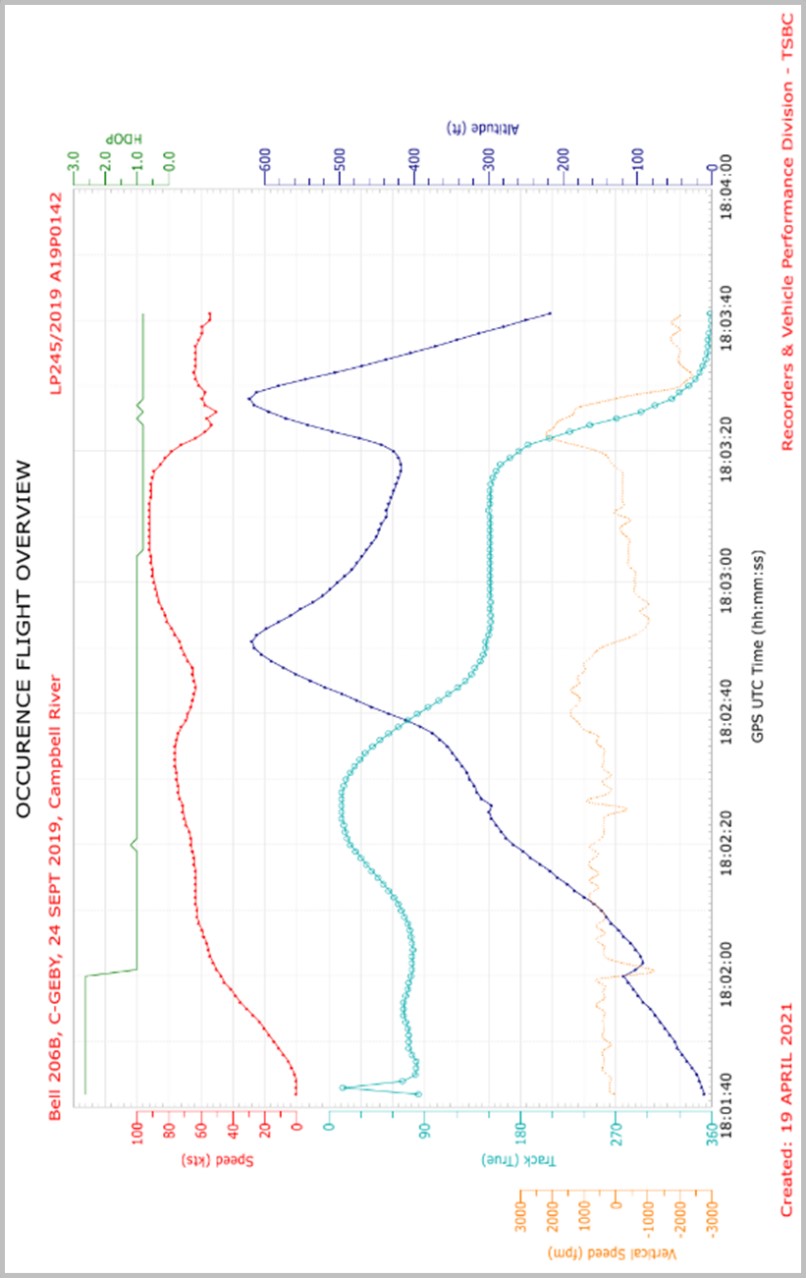
The helicopter climbed to the east and, once beyond the coastline, headed southeast. At 1102:50, the helicopter levelled off briefly at 615 feet above sea level (ASL) and then began to descend at a rate of approximately 400 fpm, at 87 knots ground speed (Figure 1, point A), accelerating to 92 knots ground speed. At 1103:17, when the helicopter was at 417 feet ASL, it entered a right-hand turn (Figure 1, point B). During the turn, the helicopter’s ground speed decreased and its altitude increased to a peak of 620 feet ASL. At that peak altitude, the helicopter was rolling out of the turn, and it began to descend at a rate of approximately 1950 fpm, with a ground speed of 63 knots (Figure 1, point C). This descent was maintained for 4 seconds on a north-northwest track. Over the next 5 seconds, the helicopter’s ground speed decreased to 54 knots. When the helicopter was at 200 feet ASL, at 1103:40, the helicopter departed controlled flight and the main rotor blade contacted the tail boom.
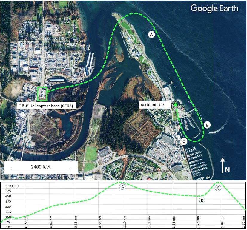
The helicopter descended vertically and, at 1103:43, it struck a building located 0.8 nautical miles east of the point of departure. The helicopter’s tail boom struck 2 trucks that were parked at the building (Figure 2). The pilot received fatal injuries. No one on the ground was injured. After the helicopter came to rest, a post-impact fire started. No emergency locator transmitter signal was detected by the search and rescue satellite system.
1.2 Injuries to persons
The pilot, who was the sole occupant, was fatally injured.
| Degree of injury | Crew | Passengers | Persons not on board the aircraft | Total by injury |
|---|---|---|---|---|
| Fatal | 1 | – | 0 | 1 |
| Serious | 0 | – | 0 | 0 |
| Minor | 0 | – | 0 | 0 |
| Total injured | 1 | – | 0 | 1 |
1.3 Damage to aircraft
The helicopter was destroyed due to significant impact forces and by the post-impact fire.
1.4 Other damage
The roof and exterior walls of the building that was struck by the helicopter were damaged by the impact and post-impact fire. Two vehicles that were parked adjacent to the building were also damaged. Soil remediation was performed at the site due to fuel and oil that spilled from the helicopter.
1.5 Personnel information
The pilot held a commercial pilot licence for helicopters and a type rating for the Bell 206 series of helicopters. The licence was validated with a current Category 1 medical certificate. His last pilot competency check for the Bell 206 series of helicopters was conducted on 13 November 2018, and was valid until 01 December 2019. Engine-out emergencies and forced landings were evaluated during the competency check with no deficiencies noted.
| Pilot licence | Commercial Pilot Licence (CPL) – Aeroplane (A) single-engine land and sea (SELS) and Commercial Pilot Licence (CPL) – Helicopter (H). |
|---|---|
| Type ratings | A119, BH06, BH407, BH47, EC30, HU50, R66, RH22, RH44 |
| Medical expiry date | 30 October 2019 |
| Total flying hours | 16 222 |
| Flight hours on type | 5642 |
| Flight hours in the 7 days before the occurrence | 3.0 |
| Flight hours in the 30 days before the occurrence | 6.2 |
| Flight hours in the 90 days before the occurrence | 12.6 |
| Flight hours on type in the 90 days before the occurrence | 12.6 |
| Hours on duty before the occurrence | 4 |
| Hours off duty before the work period | 12 |
1.6 Aircraft information
The occurrence helicopter was purchased from an operator in South America in 2016, and imported into Canada in 2017. Documents related to importation into Canada were completed in March 2019. The helicopter underwent extensive maintenance between 2017 and 2019, including the installation of a replacement turboshaft engine (Rolls-Royce M250-C20B) on 25 February 2019. This engine had previously been installed on a Hughes 369 helicopter and then on a Bell 206B3 helicopter before being purchased by E & B Helicopters Ltd.Footnote 3
As part of the process to obtain a Canadian certificate of airworthiness, a work order package was created to track all defects, maintenance required, and component parts removed or installed on the helicopter. This package also included scheduled and unscheduled inspections as required by both the airframe and engine manufacturers. A maintenance entry dated 25 February 2019 indicated that all airworthiness directives applicable to the occurrence helicopter were complied with up to 18 February 2019.
By late March 2019, the occurrence helicopter began to be flown regularly and, according to the aircraft journey log, had accumulated approximately 140 flight hours before the accident. However, a review of flight tracking data following the accident revealed that several flights had not been logged in the aircraft journey log, so the exact time in service can only be estimated (Table 3). From the time the engine was installed until the accident flight, there were no defects or maintenance activities related to engine power issues recorded in the aircraft journey log.
| Manufacturer | Bell Textron Canada Ltd. |
|---|---|
| Type, model and registration | Helicopter, 206B, C-GEBY |
| Year of manufacture | 1981 |
| Serial number | 3375 |
| Certificate of airworthiness issue date | 05 March 2019 |
| Total airframe time | 4952.1 |
| Engine type (number of engines) | Rolls-Royce M250-C20B (1) |
| Rotor type (number of blades) | Semi-rigid (2) |
| Maximum allowable takeoff weight | 1451.5 kg |
| Recommended fuel types | Jet A, Jet A-1, Jet B |
| Fuel type used | Jet A |
1.6.1 Engine fuel system
1.6.1.1 Engine fuel system configuration
The occurrence helicopter was equipped with a BendixFootnote 4,Footnote 5 engine fuel control system that had one 3 cubic inch fuel accumulator and one 6 cubic inch accumulator installed. It did not have a double check valve.
The instructions detailed in the engine manufacturer’s installation bulletinFootnote 6 require two 6 cubic inch accumulators and a double check valve. The accumulators and check valve dampen fuel system instability due to torsional vibrations inherent in the 2-bladed rotor system of the Bell 206 series of helicopters. This instability can result in power fluctuations.
Allison Gas Turbine performed test trials in the late 1980s using a Bell 206B helicopter outfitted with a Model 250-C20R/2 engine for fuel system testing, as well as measuring rotor droop. The tests were conducted with 4 accumulator/check valve combinations, one of which was the same as the occurrence helicopter’s.
Test results focusing on the 4 accumulator/check valve configurations indicated that rotor droop during autorotation recoveries was reduced by lowering the control system damping. This was done by decreasing the accumulator volume or eliminating the double check valve. Damping was measured for each configuration. All were acceptable except for the stand-alone 6 cubic inch accumulator, which had a noticeably long decay. No complete power losses were recorded in the test results.
Engine records reflected that the engine had been previously installed on a Hughes 369 series helicopter before being installed on a Bell 206B3 and then, finally, on the occurrence helicopter. The Hughes 369 series helicopter type uses a 5-bladed main rotor system and requires only one 3 cubic inch accumulator.
Section 571.02 of the Canadian Aviation Regulations (CARs) requires persons who perform maintenance work to follow the manufacturer’s recommendations or equivalent practices.Footnote 7 Additionally, Transport Canada (TC) issued an Airworthiness Notice to clarify for aircraft maintenance engineer and operators “the need to comply with manufacturers’ service bulletins, service letters, etc.”Footnote 8 The aircraft’s technical records did not contain any indication that the installation bulletins for the Bendix engine fuel system were reviewed or referred to. It was determined that the maintenance department at E & B Helicopters Ltd. did not refer to the bulletins.
In June 1991, the TSB issued recommendation A91-21 in response to a fatal accident involving a Hawker-Siddeley HS-748.Footnote 9 The Board recommended that
the Department of Transport clarify the operator compliance requirements with respect to Letters-to-Operators.
TSB Recommendation A91-21
In its September 2021 response to this recommendation, TC stated that it is working on a notice of proposed amendment to introduce an evaluation program for CARs Part VII operators to clarify operator responsibilities regarding Letters-to-Operators. A possible publication to the Canada Gazette, Part I is planned for late 2022 or early 2023.Footnote 10
1.6.1.2 Previous power reduction event
On 18 September 2019, during a flight conducted by the occurrence pilot, the occurrence helicopter experienced a reduction (droop) in main rotor rpm (about 20%). The pilot took immediate action by lowering the collective and “beeping-up” the droop compensator. Footnote 11 This defect rendered the helicopter unserviceable Footnote 12 and was reported to E & B Helicopters Ltd. maintenance staff; however, contrary to the company operations manual, Footnote 13 the maintenance control manual, Footnote 14 and the CARs, Footnote 15 it had not been recorded by the pilot in the aircraft journey log.
Company maintenance checked all fuel and air lines to and from the fuel system components and then performed an engine ground run and leak check. No defects were found. This maintenance activity was also not recorded in the aircraft journey log, under the direction of the pilot and contrary to the CARs.
Following this maintenance activity, a 12-minute test flight was conducted, and no loss of power or main rotor rpm droop was experienced. This test flight was not recorded in the aircraft journey log, nor were any defects deferred, once again under the direction of the pilot and contrary to the CARs.
Following the main rotor rpm droop incident, company maintenance contacted the helicopter manufacturer and it was determined that the fuel accumulator/double check valve configuration was not correct for the helicopter. The proper parts were ordered to correct the configuration, and shipping records showed that the parts had been delivered on the day of the accident. However, they had not been installed at the time of the occurrence.
The pilot was aware of the situation, and other company pilots had been verbally cautioned by the chief pilot about an unresolved issue with the fuel system components and told not to fly the occurrence helicopter because it was still unserviceable.
1.6.2 Van Horn Aviation, LLC main rotor and tail rotor blades
The helicopter was equipped with Van Horn Aviation, LLC (Van Horn) composite main rotor and tail rotor blades. The main rotor bladesFootnote 16 were installed per Supplemental Type Certificate (STC) SH16-46 issued by TC on the basis of approval by the U.S. Federal Aviation Administration (FAA). The blades were manufactured in March 2017 and were purchased and installed new on the helicopter in January 2019.
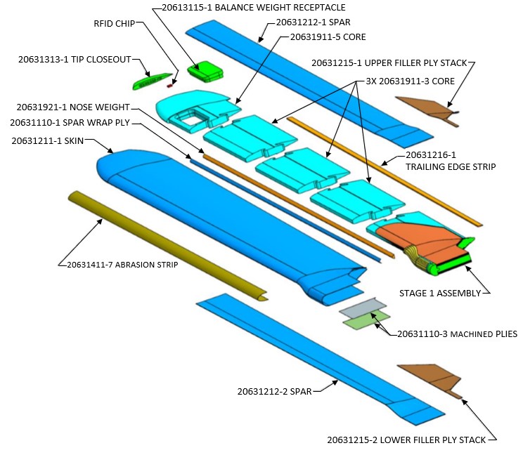
The Van Horn composite main rotor blade is dimensionally (span and chord) the same as the Bell aluminum blade. The blades are of a monocoque construction with carbon/epoxy skin material without a traditional D-spar. The D-spar is replaced by various layers of carbon/epoxy material (laminate stacks) on the upper and lower skins (Figure 3). Flight characteristics of the blades are similar enough that no changes to the performance section of the Bell 206B rotorcraft flight manual were required.
In the summer of 2020, a newer versionFootnote 17 of the main rotor blade was approved by the FAAFootnote 18 and replaced the original part number. The main difference between the 2 versions is that the newer blade has a different carbon fibre ply count and orientation. According to Van Horn, the “[p]ly adjustment along with changes to the mass distribution provides a softer ride […].”Footnote 19 In total, 152 blades (or 76 sets) of the original main rotor blade had been sold before the newer main rotor blades were approved. The last original blades were manufactured in April 2018. It is not known how many original blade sets are in operation in Canada; however, it is estimated that there are 6.
The Van Horn composite tail rotor blades were installed on the helicopter per TC’s STC SH10-22 in 2011.
1.6.3 Weight and balance
The helicopter departed the base of operations with about 40 gallons of fuel, which was adequate for the planned flight.
The cargo recovered at the accident site was weighed and it was determined that the helicopter departed within the weight and balance envelope. However, contrary to the E & B Helicopters Ltd. company operations manual,Footnote 20 the cargo was unsecured: 1 case of beer was loaded on the forward floor pan of the cockpit, on the passenger side, and fire wood and groceries were loaded on the rear passenger seats. Two 20-pound cylinders of propane were loaded in the cargo area along with a 5 U.S. gallon red plastic container consistent with one that would carry fuel.Footnote 21
1.7 Meteorological information
The aerodrome routine meteorological report (METAR) for Campbell River Airport (CYBL), BC, issued at 1100 and valid at the time of the occurrence reported the following:
- wind direction variable at 2 knots
- visibility 20 statute miles
- scattered clouds at 1200 feet and a broken ceiling at 8000 feet above ground level
- temperature 15 °C
- altimeter setting 30.23 inches of mercury
Weather was not considered a factor in this occurrence.
1.8 Aids to navigation
Not applicable.
1.9 Communications
Not applicable.
1.10 Aerodrome information
Not applicable.
1.11 Flight recorders
The aircraft was not equipped with a flight data recorder or a cockpit voice recorder, nor was either required by regulation. However, the aircraft was equipped with a flight tracking device that recorded several parameters of data. See section 1.16.2 Helicopter performance analysis.
1.12 Wreckage and impact information
The wreckage was recovered and transported to the TSB regional facility in Richmond, BC, for further examination with the participation of a safety investigator from the helicopter manufacturer. All fuselage fractures, fuel and hydraulic system lines and components, and flight controls were examined to determine continuity and modes of failure. No pre-existing defects were found. The damage to the cyclic control was such that the position of the twist grip throttle was inconclusive.
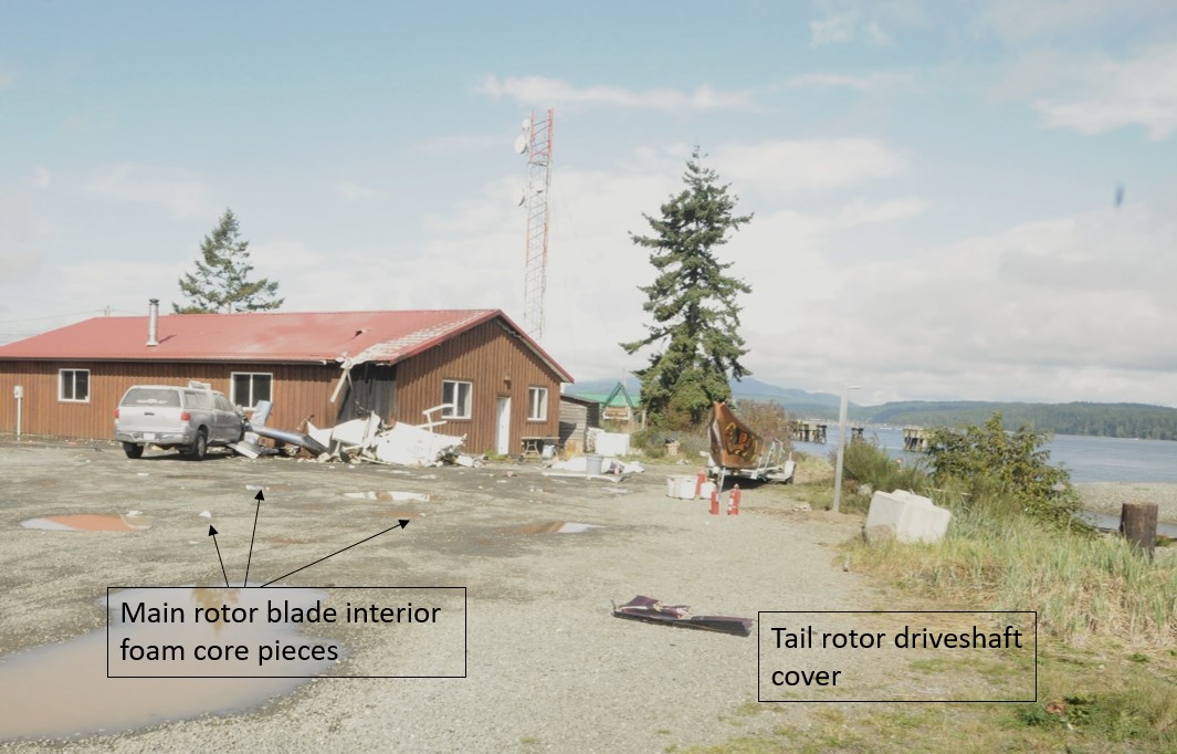
It was noted at the accident site that the most aft section of the tail rotor drive shaft cover was found 25 m before the impact location, along the flight path. Impact marks on the drive shaft cover were consistent with it being struck by a main rotor blade; however, the underlying tail rotor drive shaft was not significantly damaged. Pieces of foam consistent with the material found in the core of the main rotor blades were located several metres from the accident site.
1.12.1 Summary of eyewitness observations
The final 20 seconds of the helicopter’s flight were observed by 33 people in various locations around the accident site. The following is a summary of those observations:
- 7 described a “whop whop” sound while the helicopter turned from south to north;
- 15 described either no engine sound or sounds associated with an engine not developing normal power;
- 15 described wobbly or erratic movement of the helicopter in the moments leading up to the accident;
- 6 described a rotor blade detachment, or something coming off the helicopter during the final moments of flight;
- 10 described a very slow or near-stopped main rotor rotation just before the departure from controlled flight; and
- 19 described a straight-in or vertical drop to the ground.
1.12.2 Examination of the engine and engine systems
The engine was sent to an approved maintenance and overhaul facility in Vancouver, BC, to be examined in detail because damage signatures indicative of slow rotation at impact had been seen during the TSB’s initial examination of the engine. Teardown examination of the engine with the assistance of the manufacturer’s representative, and with the TSB in attendance, confirmed that the engine’s rotational speed had substantially decelerated when the helicopter impacted the ground. Aluminum shavings from crushing rotational contact between the compressor impeller and diffuser scroll had been blown back to the turbine section, but were not melted as they normally would be by the high operating temperatures found in the combustor section. This is consistent with an engine that has flamed out.
The fuel components from the engine and airframe were sent to a maintenance facility in Winnipeg, Manitoba, for bench testing and follow-up disassembly and examination. A TSB investigator was in attendance.
Even though the fuel control unit, governor, fuel pump, engine compressor discharge air pressure filters, and fuel check valves were damaged in the impact and post-impact fire, their condition was acceptable to be tested. These components performed satisfactorily on test bench and were subsequently disassembled. The only discrepancy noted was that the configuration of the accumulators and check valve components of the Bendix fuel control system was not appropriate for installation on a Bell 206 series helicopter, as discussed in section 1.6.1.1 Engine fuel system configuration.
1.12.3 Examination of the main rotor blades, tail rotor blades, and associated components
1.12.3.1 Visual examination
Staff at the TSB Engineering Laboratory in Ottawa, Ontario, conducted an examination of the main rotor blades with the manufacturer present. The examination identified that the damage to both blades featured characteristics of different failure mechanisms, namely fibre breakage, ply separation, delamination, and debonding (Figure 4). See Appendix A – Summary of main rotor blade visual damage.
![Overall view of both main rotor blades (serial numbers A084 [top] and A085 [bottom]) and general description of damage (Source: TSB)](/sites/default/files/eng/rapports-reports/aviation/2019/a19p0142/images/a19p0142-figure-04.jpg)
On blade A084, 2 diagonal fractures (45° from the blade’s edge) were observed on the upper skin (stations 60 and 75), indicated by dashed white lines in Figure 4. A relatively short section of trailing edge strip, indicated by the thick white arrow, had separated from the blade, and the trailing edge bond had fractured, leaving an 8-foot-long opening. Red paint transfer from the roof of the building struck by the helicopter was found on the lower surface of the metallic abrasion strip installed on the leading edge of the whole blade, but no dents on the blade were observed. The majority of the foam core material where the trailing edge had opened up was missing.
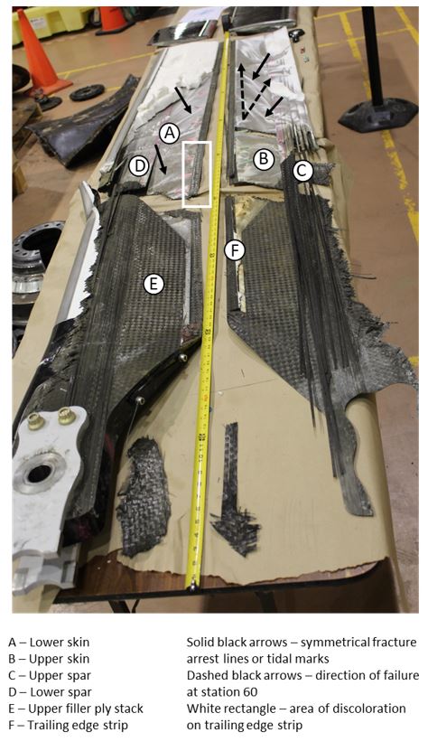
Blade A085 had 2 chordwise fractures near the root (stations 24 and 60), indicated by dashed white lines in Figure 4; a V-shaped partial fracture of the upper skin at station 99, indicated by dotted white lines; a trailing edge bond fracture with a 9-foot-long opening; and a dent on the leading edge, as indicated by the thick white arrow. Similar to blade A084, the majority of the foam core material where the trailing edge had opened up was missing.
Further examination of main rotor blade A084 revealed signs of progressive failure (tidal marks) where the internal foam core adhered to the upper and lower skins (Figure 5). These tidal marks indicate that the fracture between the foam core and the skins was from inboard to outboard, starting from the main fracture at station 60 and going from trailing edge to leading edge. Main rotor blade A085 exhibited similar tidal marks where the internal foam core adhered to the upper and lower skins.
The main rotor mast, pitch links, and swashplate drive collar sustained damage that was consistent with the helicopter striking the roof of the building and then the ground.
Damage to the tail rotor blade was found to be consistent with the blade impacting the vehicle at the accident site. The tail rotor gear box and pitch links were found to be functional.
1.12.3.2 Microscopic examination of main rotor blade A084
A polymer composite is a bonded microstructure that features a matrix, functioning as an adhesive, that bonds all fibres together in a designed pattern. The critical aspects of a polymer composite, in terms of structural integrity, are the bonding strength and durability of the fibre/matrix interface.
After a macroscopic and microscopic examination of main rotor blade A084, signs of rubbing were found where the upper and lower main rotor blade skins come together at the trailing edge strip, along with loose carbon filaments and matrix rolling. Matrix rollers are a unique feature associated with fatigue failure of polymer composites despite the fact that they may have different types of fibre and matrix design. Footnote 22 The identification of matrix rollers in both interlaminar Footnote 23 and intralaminar Footnote 24 fracture surfaces suggests that fatigue failure was likely involved in the fracture of the blade.
In addition to the matrix rollers, bare fibres were observed on the rubbed fracture surface of the lower skin to trailing edge strip bond joint. This is consistent with a fibre-matrix interface failure and a resulting reduction in bonding strength.
A high density of matrix debris was also observed in the rubbing area. Research literatureFootnote 25 indicates that the longer a pre-existing crack has existed, the higher the concentration of matrix debris on the fracture surface.
In the separated trailing edge strip, inboard of the main fracture surface (station 60), multilayer delamination was observed. Blunt impact can result in multilayer delamination, but no associated signs of an impact in that area were noted. However, matrix rollers and a high density of composite debris were observed on the fracture end of this trailing edge strip section. This indicates that a translaminarFootnote 26 fracture likely occurred before the impact with the building and ground.
1.12.3.3 Conclusions of visual and microscopic examinations
The diagonal fracture lines identified during the visual examination of main rotor blade A084 are consistent with damage caused by torsional load. On both main rotor blades , the 90° change in the direction of the diagonal fracture line implies a change in the direction of torsional loads, suggesting alternating torsional loads were involved. These observations suggest that the damage on the 2 main rotor blades likely occurred in flight before the impact with the building and the ground.
The presence of matrix rollers observed in both interlaminar and intralaminar fracture surfaces of the lower skin, trailing edge strip, and lower skin to trailing edge strip bond joint of main rotor blade A084, all located in a region close to station 60, suggests that fatigue damage existed before the occurrence. Other observations supporting this include extensive rubbing of the fracture surface, extensive fibre/matrix interface failure, the presence of a high density of matrix debris with rounded edges, and debris accretion.
The degree to which this fatigue damage played a role in the failure of the main rotor blade could not be established with certainty.
1.12.4 Other accident involving Van Horn composite main rotor blades
On 08 August 2020, a Bell 206B helicopter (registration N284S) crashed approximately 39 nautical miles southeast of Marathon, Texas, United States. The pilot sustained serious injuries, and the 3 passengers on board were fatally injured. That aircraft was equipped with Van Horn composite main rotor blades that had the same part number as the blades installed on the aircraft involved in the occurrence being investigated by the TSB.
The U.S. National Transportation Safety Board (NTSB) Aviation Accident Preliminary ReportFootnote 27 on the occurrence in Texas stated that the pilot felt slight vibrations and informed the passengers he was going to conduct an emergency landing. The vibrations intensified with a loss of manoeuvrability, and the helicopter lost lift and impacted terrain short of the landing area. The pilot stated that the engine had been operating normally.
The main rotor blades are currently being examined by the NTSB Office of Research and Engineering.
1.12.5 Examination of the annunciator panel lights
The annunciator panel lights were recovered and examined at the TSB Engineering Laboratory. The following 4 annunciators were determined to have been lit at impact: BAGGAGE DOOR, ENG OUT (engine out), GEN FAIL (generator fail), and ROTOR LOW RPM.
Each annunciator light comprises 2 light bulbs. The investigation determined that 1 of the 2 BAGGAGE DOOR light bulbs was lit at the time of impact; however, the status of the other light bulb could not be determined.
1.13 Medical and pathological information
The TSB contracted an independent cardiologist to review the occurrence pilot’s medical records for cardiovascular risk factors. This review included a 10-year history of TC medical examination reports and family physician documents. The cardiology review indicated that the pilot had several cardiovascular risk factors, including: age (70 years or older), obesity,Footnote 28 smoker, elevated blood pressure, elevated blood lipids, elevated blood sugars, and elevated liver enzymes.
Of these risk factors, only age, smoking, and elevated blood pressure were documented in the pilot’s TC medical examination reports. In addition, results from recent laboratory tests ordered by the pilot’s family physician that reflected cardiovascular risk levels, were not recorded on the TC medical examination reports. Although the TC medical examination reports had documented some of the pilot’s risk factors, these had not been combined with results from tests ordered by the pilot’s family physician to assess his overall risk of a cardiovascular event. The independent review concluded that the pilot’s actual annual risk for a sudden incapacitating cardiovascular event exceeded 5% per year.
1.13.1 Hypertension
Hypertension, or high blood pressure, is a key factor in the assessment of cardiac health. As a result, TC Civil Aviation Medical Examiners (CAMEs) are required to measure and record an applicant’s blood pressure to assess whether the systolic and diastolic blood pressures are below the normal limit, which, according to TC guidelines,Footnote 29 is 140/90 millimetres of mercury (mmHg) (systolic over diastolic).Footnote 30 If a person’s blood pressure is greater than this normal limit, a specific visit should be scheduled by the CAME to assess for hypertension.Footnote 31
The occurrence pilot had been diagnosed with hypertension 6 years before the occurrence. However, despite treatment, he repeatedly presented with elevated blood pressure during examinations by both his family physician and CAMEs.
In 2015, the TC Regional Aviation Medical Officer requested that the pilot undergo 24-hour ambulatory blood-pressure monitoring, which showed peak blood-pressure levels indicative of hypertension. However, since 2015, there were no further out-of-office assessments provided to or requested by any of the CAMEs who assessed the pilot or by his family physician.
In the 2.5 years before the occurrence (2017-2019), the pilot continued to present with high in-office blood-pressure readings, but reassured both his family physician and the CAMEs, via subjective verbal reports or handwritten blood-pressure readings from home, that when his blood pressure was taken at home (out-of-office), it was always within normal limits. No printed objective data was provided, or requested, to verify this declaration.
The pilot also declared to the CAMEs that his family physician had his hypertension under control and that he was being treated with only 1 medication. This information reassured the CAMEs that the pilot’s hypertension was under control. However, the independent cardiology review conducted as part of this investigation identified that the pilot was actually being treated with 2 different hypertension-related medications, but the second was not declared on the pilot’s TC medical examination reports.
Despite not having objective data to verify the pilot’s reported out-of-office normal blood-pressure readings, his family physician and the CAMEs repeatedly attributed the in-office elevated blood-pressure readings to assumed white-coat hypertension.Footnote 32 As a result, none of them identified elevated blood pressure as a significant risk factor.
The prevalence of white-coat hypertension is estimated to be between 9% and 30%Footnote 33,Footnote 34 and more common in women, older people, non-smokers, and people with mildly elevated office blood pressure. TC recognizes that, due to the stress of potentially not being re-certified, white-coat hypertension is particularly likely in those applying for a medical certificate. However, in this case, the pilot was male, a smoker, and presented with high blood-pressure readings not only in his examinations with a TC CAME, but also at his family physician’s, when he was not being assessed for his medical certification.
1.13.2 Transport Canada aviation medical certification
The primary activity of the TC’s Civil Aviation Medicine Branch is performing medical assessments required for the certification of licensed aviation personnel. As stated in CARs Standard 424.04(1)(b),
[…] Medical Certificates are issued by the Minister of Transport through the office of the Regional Director, Aviation Licensing following receipt of:
(i) a medical examination report, provided the candidate meets the pertinent medical standards and has been assessed medically fit or fit subject to any restriction or limitation recommended by Civil Aviation Medicine Division Medical Staff.[…]Footnote 35
1.13.2.1 Medical examination
The purpose of the medical examination is to determine whether an applicant meets the standards for the issuance of a medical certificate, which is needed to validate a pilot’s licence. TC is mainly concerned with managing the risks to aviation, such as incapacitation, for the period of the licence. If necessary, further medical examination may be requested.
In accordance with CARs Standard 424.04(2)(a), “[e]very applicant for a medical certificate or revalidation thereof shall undergo a medical examination by a CAME.”Footnote 36 CARs Standard 424.17 requires that the CAME examine the pilot carefully and that the examination be “sufficiently thorough so as to determine whether the applicant meets the requirements in respect of the category of medical certificate that is applied for or in respect of which a validation is sought.”Footnote 37
TC’s Handbook for Civil Aviation Medical ExaminersFootnote 38 provides guidance to CAMEs on how to perform medical examinations and assess medical fitness. During a medical examination, CAMEs are required to complete a Medical Examination Report 26-0010. The original report should be sent to their regional office for the regional aviation medical officer to review, if required.
Holders of a commercial pilot licence (aeroplane or helicopter) require a valid Category 1 medical certificate. Commercial pilots who are under the age of 40 must renew their medical certificate, and therefore attend a TC medical examination, every 12 months. Pilots who are 40 years of age or older must renew their medical certificate every 6 months.Footnote 39
The occurrence pilot, who was over 70 years of age, regularly attended a TC medical examination every 6 months, and for each visit, a medical examination report was completed as required. In the 10 years before the occurrence, the pilot had been seen by 3 different CAMEs. The most recent CAME had been certifying the pilot every 6 months since March 2017. The pilot was due for his next medical certification the month following the occurrence.
1.13.2.2 Reporting responsibilities of family physicians
The Aeronautics Act states,
[w]here a physician […] believes on reasonable grounds that a patient is a flight crew member […] or other holder of a Canadian aviation document that imposes standards of medical […] fitness, the physician […] shall, if in his opinion the patient has a medical […] condition that is likely to constitute a hazard to aviation safety, inform a medical adviser designated by the Minister forthwith of that opinion and the reasons therefor.Footnote 40
From January 2017 to September 2019, the pilot had visited his family physician on 8 different occasions, during which multiple cardiovascular assessments and discussions took place, and 2 sets of laboratory tests were ordered. No documentation related to these visits, discussions, or tests had been sent to, or requested by, any of the 3 CAMEs that had most recently examined the pilot.
The pilot’s family physician had noted on the file that the pilot was a commercial pilot and was therefore aware of his profession. However, the investigation was unable to determine with certainty if the family physician was aware of the requirement to report to TC.
1.13.2.3 Disclosure responsibilities of pilot applicants
As CAMEs are often not the applicant’s family physician, they must rely to a large extent on information disclosed by the applicant. Disclosed information could relate to the pilot’s medical symptoms, medication use, or use of drugs such as cigarettes and alcohol.
TC recognizes that aviation personnel may not volunteer information that could affect their medical certification, typically because they fear losing their medical certificate and, in some cases, their employment. CARs Standard 424 requires an applicant to sign a statement on the medical examination report to confirm that the information provided is complete and accurate and that the applicant is aware that it is an offence in the Aeronautics ActFootnote 41to knowingly make a false declaration. However, the applicant is not required by TC to provide the results of personal medical tests, such as laboratory test results, unless these results are required as part of the civil aviation medical certification process.
1.13.2.4 Management of cardiac-related illness in commercial aviation in Canada
The Handbook for Civil Aviation Medical Examiners advises CAMEs that the risk of a fatal accident occurring as a result of medical incapacitation of a pilot is dependent on a number of factors, such as the amount and type of flying or the presence of other qualified aircrew, all of which must be taken into consideration in addition to the known risks of a particular medical condition.Footnote 42 For a Category 1 medical, the pilot is required to “not suffer from any disease or disability which may render the applicant liable to become unable to operate an aircraft safely.”Footnote 43
Heart disease, especially in the presence of other diseases, such as diabetes, places the applicant in a potentially high-risk category for an incapacitating event. CARs Standard 424 stipulates that “[t]he applicant shall not possess any abnormality of the heart, congenital or acquired, which is likely to interfere with the safe operation of an aircraft.”Footnote 44
Heart disease is any condition that affects the structure or function of the heart. There are 4 main types of heart disease:
- Heart rhythm disorders (arrhythmias)
- Structural abnormalities
- Heart failure
- Coronary heart diseaseFootnote 45,Footnote 46
It is essential for the CAME to identify and document the presence of any heart disease or associated diseases during a civil aviation medical exam.
1.13.2.5 Identifying heart disease during the aviation medical examination
When examined by a CAME, some applicants may present with obvious symptoms and/or documentation indicating past or present heart disease. However, others may not present with any single obvious indicator or have any history of cardiac illness. For example:
[m]any [individuals] may have ischemic episodes without knowing it. […] People with angina also may have undiagnosed episodes of such silent ischemia. In addition, people who have had previous heart attacks or those with diabetes, are especially at risk for developing silent ischemia.Footnote 47
Ischemic heart disease is a term given to heart problems caused by narrowed heart arteries. This may also be called atherosclerosis, which involves the arteries becoming narrowed as a result of fatty deposits.Footnote 48
It is difficult for CAMEs to suspect heart disease or estimate an applicant’s risk of a cardiac-related incapacitation event when the applicant presents with no confirmed and documented heart disease. Guidance for assessing the risk factors associated with heart disease to help CAMEs ascertain the risk profile of each applicant is available in the CARs,Footnote 49 Figure 2 in the Handbookfor Civil Aviation Medical Examiners,Footnote 50 and the Handbook’s link to the cardiovascular fitness assessment guide.Footnote 51 This guidance material reflects recommendations made during a TC Civil Aviation Medicine Branch aviation cardiology workshop in 2010 and replaces the former TC cardiovascular guidance from 2002.
The Handbook for Civil Aviation Medical Examiners outlines the various risk factors for heart disease, which include age, gender, obesity, blood pressure, smoking, family history of heart disease, results from cardiac tests, and symptoms of heart disease, such as chest pain and shortness of breath. CAMEs are also provided with information on the Framingham risk scoring system. This system takes into account information on 6 key risk factors: age, blood lipids, blood pressure, history of diabetes, smoking status, and possibly family medical history. Once this information is collected, the CAME will assign scores to each risk factor to estimate the overall risk profile of the individual, i.e. their risk of having a cardiac-related incapacitating event.
To assess an applicant’s risk factors, CAMEs are provided with guidance on 4 techniques:
- Medical interview: during the interview, the CAME requests information on the applicant’s cardiac-related health and any other associated health issues, such as diabetes. The CAME relies on the applicant declaring cardiac-related information, such as chest pain, any known results of medical exams or treatments, and health behaviours, such as smoking and alcohol consumption.
- Physical exam: during the physical exam, the CAME examines the applicant’s peripheral circulation and heart function, takes the applicant’s blood pressure, and uses height and weight to calculate the applicant’s body mass index.
- Review of electrocardiograms: the CAME assesses the applicant’s most recent electrocardiogram, which, for a pilot over the age of 40, must be conducted within the 12 months preceding the medical exam.Footnote 52
- Examination of other test results: CAMEs may, at their discretion, request further medical screening if they believe there are indications of a disease that must be further examined to establish medical fitness.
The results of each technique are documented on the TC medical examination report, where appropriate.
1.13.2.6 Calculating an applicant’s risk profile
The Handbook for Civil Aviation Medical Examiners stipulates that an estimated risk, calculated using any of the recommended risk estimators (e.g. the Framingham risk scoring system), of 2% per yearFootnote 53 for a sudden incapacitating cardiovascular event should be the threshold for performing enhanced screening before medical certification:
The cumulative risk conferred by the presence of more than one risk factor, even at levels only moderately above normal, can exceed that conferred by the presence of one major risk factor alone. […] If abnormalities are found, resulting in an average annual mortality risk of 1% or more, assuming an additional 1% risk of an incapacitating nonfatal event, then a license holder is considered medically unfit for an unrestricted license.Footnote 54
The Handbook also specifies that
[c]oncern about these [major modifiable] risk factors is greater in applicants with known ischemic heart disease where the absolute risk is greater.Footnote 55
The independent cardiology review conducted as part of this investigation highlighted that, based on the consensus of a multinational consortium of aviation cardiologists published in 2019, this 2% is based on a sliding scale, depending on the role and associated risk for each pilot. For single-pilot rotary wing operations, the case applicable to the occurrence pilot, a lower threshold of 1% is more appropriate.Footnote 56 These guidelines are not included in the cardiovascular assessment guidelines in the Handbook for Civil Aviation Medical Examiners because this section of the Handbook was published in 2012.
This investigation reviewed the information TC provides to CAMEs for medical examinations, and determined that the guidance does not mandate the use of the Framingham risk scoring tool, and in no way is the tool linked with the use of the TC medical examination report. In addition, nothing on the medical examination report specifically prompts the CAME to use the Framingham risk scoring system or to consolidate key risk factors to determine the applicant’s overall risk profile.
On the occurrence pilot’s TC medical examination reports, there was neither a consolidation of the risk factors to determine the pilot’s overall risk profile nor use of the Framingham scoring system or any other risk calculator. As such, there was no risk assigned and no comparison to the TC-advised 2% threshold as part of the civil aviation medical risk profiling.
The effectiveness of TC oversight of medical risk factors, specifically with respect to cardiovascular and hypertensive issues in pilots, has been addressed in previous TSB reports.Footnote 57
1.13.3 Cause of death
The BC Coroner’s Office determined the cause of death to be blunt-force trauma. Although no acute coronary occlusion was observed (such as a heart attack), post-mortem results did confirm the presence of extensive atherosclerotic coronary artery disease in all 4 major coronary arteries, with significant (>75%) stenosis.Footnote 58 The independent cardiology review confirmed that with these autopsy results, it is conceivable that in the presence of a stressful situation, such as an in-flight emergency, the pilot could have experienced cardiac symptoms, such as chest pain, as a result of insufficient blood flow, and possibly resultant cardiac arrhythmias with lightheadedness or even incapacitation.
1.14 Fire
Video captured of the impact sequence showed that the fuel was not contained within the fuel cell during the impact sequence. The uncontained fuel’s contact with the hot engine components resulted in the post-impact fire. First responders were on scene within minutes with portable extinguishers. Firefighters arrived approximately 5 minutes after the impact. The fire was extinguished before significant damage was done to the building or helicopter.
1.15 Survival aspects
The pilot was not wearing a helmet and, contrary to the CARs,Footnote 59 was wearing only the lap belt portion of the safety belt; he was not wearing the available shoulder harness.
The accident was not survivable due to the impact forces involved. The helicopter was equipped with a 406 MHz emergency locator transmitter. However, due to the impact forces and post-impact fire damage, the emergency locator transmitter did not emit a signal.
1.16 Tests and research
1.16.1 Photogrammetric analysis of video
A security camera mounted on a building 600 feet southeast of the accident site recorded the final moments of the helicopter’s flight path, as well as the impact and subsequent falling debris. The video file was sent to the TSB Engineering Laboratory in Ottawa, Ontario, for analysis. The analysis determined that the main rotor blades were stationary, or not rotating, during the last moments of the descent (Figure 6).
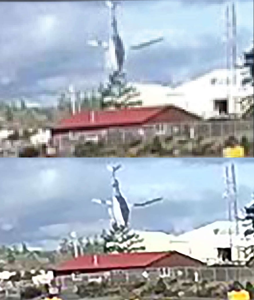
It was noted that the rotor blade on the left side of the helicopter in Figure 6 appeared to be at an approximate angle of −46° from parallel to the roll axis; however, it could not be determined whether this was due to the main rotor head being at that angle, whether a break or bend had occurred in the rotor blade before impact leaving only the outboard section of the blade at that angle, or whether there was a combination of these 2 scenarios.
The rotor blade on the right side of the aircraft was observed to have a bend or break 1.6 m from the main rotor hub, with the outboard portion appearing to be at an upward angle of approximately 27° to 38°. The video analysis suggested that this damage occurred before impact with the roof of the building.
The falling debris that followed the helicopter was a very close match to the recovered piece of the tail rotor drive shaft cover. It is possible that the debris seen in the video was the piece of the cover and was not attached to the helicopter before the impact with the building. Also visible in the video are the main rotor blade interior foam core pieces falling after the helicopter had struck the building.
1.16.2 Helicopter performance analysis
The TSB laboratory was asked to analyze the helicopter’s performance based on the GPS (global positioning system) data collected from a Latitude SkyNode S200 flight-tracking unit that was on board the helicopter. The occurrence flight was captured in the memory of the SkyNode unit, and 119 seconds of data, recorded at 1 Hz, was used to complete the performance analysis.
Each second of data that was recovered included time, latitude, longitude, GPS altitude, ground speed, track, and the horizontal dilution of precision Footnote 60 (Appendix B – Flight data plot). It was noted that the last 2.5 seconds of the flight were not recorded by the SkyNode unit. The cause for the premature ending of the recording could not be determined.
The analysis focused on the final descent after the helicopter had reversed course after it had reached its peak altitude. In particular, the helicopter’s descent was examined to determine whether it was consistent with an autorotation and whether it had been affected at all by pilot inputs on the flight controls.
This analysis, the results of which were independently verified by Bell Textron, determined that during the last 10 seconds of recorded flight data, assuming the helicopter was in an unpowered autorotation, the average main rotor speed would have been 110% to produce the descent rate and ground speed recorded. The consistency of the parameters during the descent indicates that the pilot made no inputs on the flight controls that would have slowed the main rotor rpm.
In a fully functioning helicopter, an increase in collective during an autorotation will result in changes in rotor rpm, rate of descent, and forward speed. The photogrammetric analysis of the video, however, showed that the main rotor blades had stopped rotating before impact with the ground. It may be possible for a significantly malformed blade to arrest the rotation of the main rotor blades in less than 5 seconds due to abnormal aerodynamic loads and blade profile drag.
1.16.3 TSB laboratory reports
The TSB completed the following laboratory reports in support of this investigation:
- LP245/2019 – Helicopter Performance Analysis
- LP254/2019 – Annunciator Lamp Analysis
- LP032/2020 – Rotor Component Examination
- LP034/2020 – Photogrammetric Video Analysis
- LP029/2021 – Main Rotor Blade Examination
1.17 Organizational and management information
1.17.1 E & B Helicopters Ltd.
E & B Helicopters Ltd. was a privately owned company providing commercial helicopter services to the public. The company was issued an air operator certificate for CARs Subpart 702 (Aerial Work) and Subpart 703 (Air Taxi) operations. It operated a fleet of 10 single-engine helicopters and had approximately 20 employees. The company provided flight training, aerial work, and air taxi service from its main base in Campbell River, BC, and a sub-base in Gold River, BC. Maintenance was primarily carried out through its own approved maintenance organization (AMO), with outside AMOs contracted as required.
The occurrence pilot was the owner of the company, the accountable executive, and the operations manager. On 04 January 2021, E & B Helicopters Ltd. surrendered its air operator certificate to TC and ceased flight operations.
1.17.2 Transport Canada oversight
A 10-year review of TC oversight activities for this company revealed there were several deficiencies identified in the past; however, there had been an improvement within its practices and internal processes. The latest process inspection, just a week before the occurrence, did not produce any findings of non-conformance.
1.18 Additional information
1.18.1 Safety culture
Safety culture can be defined as “[s]hared values (what is important) and beliefs (how things work) that interact with an organization’s structures and control systems to produce behavioural norms (how we do things around here).”Footnote 61
The definition of safety culture, as a description of what the members of an organization collectively believe is important and valuable, is a critical determinant of how people behave on a day-to-day basis. Safety culture tacitly communicates expectations to new and existing members of an organization. As a result, it impacts both the degree to which work is accomplished safely and the degree to which members of an organization participate in safety management processes.
Another description of safety cultureFootnote 62 places organizations on a continuum from extremely discouraging to extremely supportive. A supportive safety culture is characterized by actively encouraging the sharing of safety information, accepting responsibility for safety, free and open reporting of mistakes, and encouraging and promoting new ideas.
The pilot, who performed the roles of both accountable executive and operations manager, was responsible for the daily operational practices. The investigation determined that the pilot also had close oversight of maintenance-related decisions. In the years before the occurrence, the company was busy and aircraft were used frequently and, as a result, those carrying out the organization’s operational and maintenance supervisory roles made and executed decisions in the interests of safety and regulatory conformance, as required. Occasionally, however, these decisions were overruled by senior management. Within the year before the occurrence, revenue decreased and financial factors became a priority in both operational and maintenance-related decisions. As a result, senior management overruled these supervisory decisions more frequently.
In practice, many operational and maintenance-related decisions were being made based on a single opinion, rather than a process of validation by a hierarchy of independent and skilled supervisors. These decisions included ones related to the accountable executive’s flights, where he was the only one who made decisions related to the supervision, planning, and dispatch of his flights. As a result, there was no effective independent process in place to detect and rectify unsafe practices. On the day of the occurrence, despite having an unresolved defect and being told the aircraft was not serviceable, the pilot overruled maintenance and operational personnel and used the aircraft for the occurrence flight.
1.18.2 Power loss and autorotation
The TC Helicopter Flight Training Manual describes an autorotation as
the condition of flight where the rotor is driven by aerodynamic forces, with no power being delivered by the engine. Autorotational flight is a basic and essential emergency procedure at which every helicopter pilot must be proficient. […] During autorotation the helicopter is still flying despite the fact that the engine is not delivering motive power to the rotors. It remains fully manoeuvrable albeit in descending flight. Remember also that the airflow is now upward through the disc rather than downward as in powered flight.Footnote 63
The Bell B206B flight manual states that the following steps should be performed for entering, sustaining, and landing from an autorotation:
Collective pitch — Adjust as required to maintain rotor RPM, 90% to 107%. […]
Cyclic control — Adjust to obtain the desired autorotative airspeed for existing conditions.
If altitude permits, attempt Engine Air Start.
At low altitude, close the throttle and flare as required to lose excessive speed.
Apply collective pitch as the flare effect decreases to further reduce forward speed and cushion the landing. […]
It is recommended that level touchdown be made prior to passing through 70% rotor RPM. Upon ground contact, collective pitch shall be reduced smoothly while maintaining cyclic in neutral or centered position. […]
Maximum airspeed for steady autorotation is [100 knots indicated airspeed (KIAS)]. Autorotation above this speed results in high rates of descent and low rotor speed. A blue radial is installed on the airspeed indicator as a reminder of this condition.Footnote 64
The procedure notes that although maintaining the rotor rpm at the high end of the operating range produces the maximum rotor energy needed to accomplish a landing, it also leads to an increased rate of descent. It also includes a warning that forward speed should be reduced to the desired autorotative airspeed for existing conditions. The minimum airspeed for an autorotation descent is 52 KIAS and for maximum glide distance, 69 KIAS.Footnote 65
The FAA’s Helicopter Flying Handbook notes that during autorotation, a pilot can conduct turns—most commonly with 90° or 180° of heading change—to facilitate landing into the wind or avoiding obstacles. Such turns should be made early so that the remainder of the autorotation is on a straight approach path.Footnote 66
1.18.3 Helicopter main rotor stall
As described in the FAA’s Helicopter Flying Handbook,Footnote 67 main rotor rpm is critical to the safe operation of a helicopter. If the main rotor rpm falls below the safe operating range and continues to decrease, the main rotor will aerodynamically stall.
As the speed of the helicopter rotor decreases, the rotor blade’s angle of attack (AOA) must be increased to support the weight of the helicopter. At a critical angle (about 15°), the airflow over the rotor blade separates, causing a sudden loss of lift and an increase in drag. During the ensuing descent, the helicopter experiences upward airflow through the rotor disk, and the resulting AOA is so high that even the application of full down collective, which reduces the AOA of the main rotor blade, cannot restore the normal airflow. The rotor does not stall symmetrically because any forward airspeed produces a higher airflow on the advancing side than on the retreating side. This causes the retreating blade to stall first, and its insufficient lift makes it descend as it moves aft while the advancing blade climbs as it goes forward. The resulting low aft blade and high forward blade lead to a rapid aftward tilting of the rotor disc sometimes referred to as rotor “blowback” or “flapback.” As the helicopter begins to descend, the upward flow of air acting on the bottom surfaces of the tail boom and any horizontal stabilizers tends to pitch the aircraft nose down. These 2 effects, combined with any aft cyclic input by the pilot in an attempt to keep the aircraft level, allow the rotor blades to blow back and contact the tail boom, and in some cases, actually sever it. Because the tail rotor is geared to the main rotor, in many helicopters, the loss of main rotor rpm also causes a significant loss of tail rotor thrust and a corresponding loss of directional control.
“Main rotor stalls in helicopters are not recoverable. At low altitude, a main rotor stall will result in an accident with significant damage to the helicopter, and at altitudes above approximately 50 feet the accident will likely be fatal.”Footnote 68 For these reasons, the early recognition of a low main rotor rpm condition and the application of the proper recovery technique are imperative.
1.18.4 Certification of Van Horn composite main rotor blades
1.18.4.1 General
On 17 February 2016, the FAA issued STC SR02577LA to Van Horn for the installation and maintenance of main rotor blade assembly part number 20631000-100 on Bell 206B rotorcraft. On 27 October 2016, TC issued STC SH16-46 for the installation and maintenance of the part on Canadian-registered Bell 206B rotorcraft.
The Van Horn composite main rotor blade was certificated in compliance with the relevant paragraphs of Part 27 of Title 14 of the U.S. Code of Federal Regulations, through to Amendment 27-47. Of interest to this investigation is the structural fatigue evaluation, which is covered in sections 27.571 and 27.573.Footnote 69
TC’s Staff Instruction (SI) 513-003 provides guidance on the level of review to be applied before accepting and issuing an STC. SI 513-003 is consistent with the Implementation Procedures for Airworthiness, an agreement between the U.S. and Canada. The agreement is based on the “mutual confidence and trust between the FAA and TCCA [Transport Canada Civil Aviation] on their technical competence, regulatory capabilities and similarities of each other’s certification and approval systems.”Footnote 70
1.18.4.2 Damage tolerance and fatigue evaluation
In accordance with FAA Advisory Circular (AC) 27-1B,Footnote 71 which establishes an acceptable means of compliance with certification requirements, Van Horn performed a structural fatigue test with simulated manufacturing defects and in-service damage.
Van Horn elected to use the “no-growth” method of fatigue testing;Footnote 72 therefore, no specific inspection requirements were generated from the test program. When this method is used, only “routine inspections for cracking, delaminations, and service damage and other limitations prescribed in accordance with [section] 27.1529 [of the U.S. regulations] are […] required.”Footnote 73 The fatigue test is used to demonstrate that damage sustained while a component is in service will not grow before the component is retired.
The fatigue test is also used to substantiate the airworthiness limitations, which establish the “mandatory replacement time, structural inspection interval, and related structural inspection procedure required for type certification.”Footnote 74 In accordance with U.S. regulations, the type, size, and location of the simulated damage to the fatigue test specimen were based on Van Horn’s primary structural element threat assessment.Footnote 75
AC 27-1B provides detailed guidance on the primary structural element threat assessment. This threat assessment, which must be submitted with accompanying rationale to the FAA for approval, should include:
- A systematic evaluation of all the location[s], types, and sizes of damage and their estimated probability of occurrence.
- A selection or elimination of this damage based on the above estimate.
- A verification that the inspection method selected is capable of detecting the damage at the size and location determined.Footnote 76
In addition, “[d]amage as determined in paragraph f.(6)(ii) of this AC for the specific structure being substantiated should be imposed at each critical area of the structure.”Footnote 77
The Van Horn primary structural element threat assessment evaluated the different types of defects identified in AC 27-1B; Footnote 78 however, with the exception of hail damage, the threat assessment contained little quantitative assessment and reference to stress/load data recorded to determine the size and location of the simulated damage. Each type of damage was assumed to be either pre-existing in the test specimen without intentional introduction, or introduced at random sizes and locations.
In accordance with AC 27-1B, the threat assessment “must be submitted with accompanying rationale to the FAA/AUTHORITY for approval.”Footnote 79 In accordance with Part 183 of Title 14 of the Code of Federal RegulationsFootnote 80 and FAA Order 8110.4C paragraph 2-5(a),Footnote 81 the FAA has the authority to use its discretion when delegating approval of data to designated engineering representatives (DERs). The DER system enables the FAA to use qualified technical people to perform certain exams, tests, and inspections that are necessary for compliance with applicable airworthiness requirements.
Records indicate that the Van Horn primary structural element threat assessment was approved by an FAA DER.
1.18.4.3 Dynamics considerations
A structural fatigue test is a cyclic test, meaning that the rotor blade is not rotating during testing. To account for the effects of the dynamic load to the structure, paragraph 27.573(d)(3) of the U.S. regulations specifies:
Each applicant must consider the effects of damage on stiffness, dynamic behavior, loads, and functional performance on all PSEs [primary structural elements] when substantiating the maximum assumed damage size and inspection interval.Footnote 82
AC 27-1B discusses dynamic loading and response requirements:
Critical parts, locations, excitation modes, and separations should be identified and substantiated. This substantiation should consist of analysis supported by tests, including tests that account for repeated loading effects and environment exposure effects on critical properties, such as stiffness, mass, and damping. This must be accomplished to assure that the initial stiffness, residual stiffness, proper critical frequency design, and structural damping are provided as necessary to prevent vibration, resonance, and flutter problems.Footnote 83
No dynamic assessment was carried out for the certification of the Van Horn composite blades. As part of this investigation, the FAA was consulted for an interpretation of the regulation. The FAA’s interpretation was that Van Horn was allowed to omit this assessment because of the method of fatigue testing used. However, Van Horn’s fatigue test did not provide any assessment on the initial and residual stiffness. There was also no information on crack growth at the end of the fatigue test, which could provide another means of assessing change in the stiffness of the blade. The FAA also stated that no sufficient testing standard exists to test the blades only under dynamic loading.
Since neither the U.S. regulations nor AC 27-1B provide obvious conditions to omit considerations for dynamic loads, TC was consulted for its interpretation of the requirement. TC’s interpretation of section 27.573 of the U.S. regulations is that consideration for dynamic loading is required.
1.18.4.4 Quality assurance
In the U.S., the quality assurance of composite structures is covered by multiple regulatory standards.
Generic requirements for quality assurance of aeronautical products are found in Part 21 of U.S. regulations: Certification Procedures for Products and Articles. Quality assurance requirements for the production of parts manufacturer approvalsFootnote 84 are found in Subpart K of Part 21 of the U.S. regulations: Parts Manufacturer Approvals.
Requirements for quality assurance specific to normal category rotorcraft are found in section 27.605 of the U.S. regulations: Fabrication methods. Although section 27.573 of the U.S. regulations: Damage Tolerance and Fatigue Evaluation of Composite Rotorcraft Structures specifically addresses the use of composite material for rotorcraft structures, it does not refer to a quality assurance system.
Guidance on quality assurance is provided in multiple FAA ACs, including:
- AC 20-107B: Composite Aircraft Structure
- AC 21-26A: Quality System for the Manufacture of Composite Structures
- AC 27-1B: Certification of Normal Category Rotorcraft
An FAA-approved quality system for manufacturing of composite structures begins with acceptance of incoming material and includes the quality assurance of significant activities during the manufacturing process. Part of the final acceptance process is a non-destructive inspection acceptance.
According to Van Horn’s manufacturing process, there are required in-process inspections to detect a variety of defects. Final acceptance of the composite blades is based on a visual inspection of the external surface. The manufacturing process does not include an inspection of internal surfaces, or criteria for identifying internal defects that may occur during production.
2.0 Analysis
This analysis will discuss the final descent of the aircraft, the structural failure of a main rotor blade, and the eventual loss of control. The analysis will also discuss the non-standard fuel system that was installed as well as the company culture surrounding the maintenance activities during the engine installation and subsequent trouble-shooting when engine power issues were encountered. In addition, the analysis will discuss the certification process of composite main rotor blades. Finally, the analysis will examine the approach taken by Transport Canada (TC) for managing cardiovascular health and hypertension in pilots.
2.1 Helicopter final descent
2.1.1 Flight path and performance
GPS (global positioning system) data showed that, during the occurrence flight, the helicopter conducted a 180° course change with a fairly tight turn radius and an abrupt climb with decreasing ground speed. Since the original flight path headed toward water, this manoeuvre was consistent with a situation involving the pilot responding to an abnormality of some kind and setting the helicopter up for an emergency landing on land.
Given the investigation’s determinations with respect to the engine, its installed fuel system configuration, its service history, and witness accounts of abnormal engine sounds, it is likely that the initiating event that led to the 180° turn was related to engine power. Also supporting this likelihood was the post-accident examination that determined that the ENG OUT (engine out) annunciator panel light bulb had illuminated before impact.
Finding as to causes and contributing factors
An engine power anomaly likely occurred while the helicopter was in cruise flight and, as a result, the pilot reversed course and entered a descent consistent with an autorotation.
For the first 5 seconds of the descent after the helicopter had started rolling out on the reciprocal track, GPS data showed the helicopter at a ground speed and rate of descent consistent with an autorotation. However, to achieve this rate of descent and ground speed, this autorotation would have resulted in a main rotor rpm of approximately 110%.
Contrary to the calculated 110% main rotor rpm, eyewitnesses observed erratic helicopter movement and slow main rotor rpm. Also supporting the existence of slow main rotor rpm is the relatively light damage from the main rotor strike on the tail rotor drive shaft cover. Lastly, in the analysis of the security camera video, the main rotor blades showed no rotational movement.
2.1.2 Main rotor blade failure
A visual and microscopic examination of the main rotor blades revealed several indications of structural failure in flight. The diagonal fracture lines observed on both main rotor blades are consistent with damage caused by torsional load. A change in the direction of diagonal fracture lines by 90° implies a change in the direction of torsional loads, suggesting alternating torsional loads were involved. This suggests that the above-mentioned damage patterns on the 2 main rotor blades likely occurred in flight before the impact with the building and the ground.
The presence of matrix rollers observed in both interlaminar and intralaminar fracture surfaces of the lower skin, trailing edge strip, and bond joint attaching the lower skin to the trailing edge on main rotor blade A084, all located in a region close to station 60, suggests that fatigue damage existed before the occurrence.
Fatigue damage was not observed on main rotor blade A085. It is unlikely that fatigue would occur on both main rotor blades and result in a materials failure on both main rotor blades at the same time.
Findings as to causes and contributing factors
At some point during the flight, the main rotors became deformed. Although indications of fatigue were present post-occurrence, the extent to which this fatigue contributed to the deformation could not be determined.
In the last moments of the flight, likely as a result of the deformed blades, the main rotor rpm decreased to a point that could not sustain autorotational flight, and the helicopter fell vertically and impacted the ground.
2.2 Engine fuel system
The engine fuel system did not have the appropriate accumulators and double check valve for the Bell 206 helicopter. During the installation of the engine, the company maintenance control system was ineffective at ensuring that the engine installation complied with the manufacturer’s recommendations, including having the correct accumulator and double check valve configuration for the Bell 206. The underlying reason behind why the guidance documentation was not followed could not be determined by the investigation.
Finding as to risk
If maintenance procedures do not include a thorough review of all related instructions and bulletins, there is a risk that an aircraft will be released into service in a non-airworthy configuration.
2.2.1 Engine power loss
The illumination of the ENG OUT (engine out) warning light and absence of rotational damage to the engine support the theory that the engine had flamed out at some point during the descent. However, the investigation could not determine what had caused the engine to stop producing power by the time the aircraft departed controlled flight and impacted the building. Although the fuel system configuration could have led to fuel system instability and potential power fluctuations, there is no information available that would suggest it would lead to a complete power loss, and there were no other indications during the examination of the engine and its systems that could explain a complete power loss.
Finding: Other
Thorough examinations of the engine and its systems did not reveal any conditions that would have prevented the engine from producing power. It could not be determined why, by the time of impact, the engine had flamed out.
2.3 Company culture
Safety culture within a company can be summarized as “how we do things around here.” When a partial loss of engine power event had occurred the week before the accident, the event was not recorded in the aircraft journey log. Maintenance activities and test flights that had been performed to troubleshoot the issue were also not recorded, which is contrary to the regulations.
The pilot was the company’s owner, accountable executive, and operations manager, and direction on how the maintenance department was to respond to the partial loss of engine power came from him. The non-conformance with TC regulations, when demonstrated by the accountable executive, established how maintenance was to be performed and was not consistent with a supportive safety culture. This contributed to a situation in which a non-airworthy aircraft was released for flight.
Furthermore, many operational and maintenance-related decisions were being made based on a single opinion, rather than a process of validation by a hierarchy of independent and skilled supervisors. These decisions included ones related to the accountable executive’s flights, where he was the only one who made decisions related to the supervision, planning, and dispatch of his flights. As a result, there was no effective process in place to detect and rectify unsafe practices.
Also inconsistent with a supportive safety culture was the way in which several opportunities to improve the safety of the flight had been missed. Wearing a helmet and the available shoulder harnesses and securing the cargo loaded into the helicopter were all safety measures that the pilot had ignored before flying.
Finding as to risk
If company management routinely deviates from regulatory requirements, there is an increased risk that an unsupportive safety culture will develop, affecting the entire organization.
2.4 Composite main rotor blade certification
2.4.1 Primary structural element threat assessment
A structural fatigue test, completed as part of the primary structural element threat assessment, is intended to ensure the continuing airworthiness of a structural component, the failure of which could be catastrophic. Results from the fatigue test substantiate the replacement time, structural inspection interval, and related structural inspection procedure required to be included in the component’s Airworthiness Limitation. Because simulated damage was introduced randomly during the fatigue test for the Van Horn main rotor blades rather than damage of probable sizes being introduced deliberately at critical locations, it was not representative of a condition where the damaged structure may withstand the loads and stresses without failure or excessive structural deformations until the damage is detected.
The dynamic load assessment helps determine the maximum damage size to be introduced into the structural fatigue test specimen. The U.S. Federal Aviation Administration (FAA) requires that the effects of damage on stiffness, dynamic behaviour, loads, and functional performance on all primary structural elements be considered when substantiating the maximum assumed damage size and inspection interval. However, no dynamic assessment was carried out for the certification of the Van Horn composite blades. If data from a dynamic assessment is not available, the fatigue test may not discover structural responses associated with this damage.
Finding as to risk
If a structural fatigue test does not include quantitative assessments and simulated damage that is of probable sizes and at critical locations as determined from a dynamic load assessment, the resulting airworthiness limitations may not be adequate to prevent failures or excessive structural deformations.
2.4.2 Non-destructive inspection
The Van Horn composite blades are certificated on the basis of the “no-growth” method, which is used to show that the structure, with specific damage present, is able to withstand repeated loads of variable magnitude without detectable damage growth, within a specified replacement time. However, Van Horn’s quality assurance process has no established inspection for internal defects following production, or criteria for the permissible size of internal defects. Therefore, it is possible that an unknown intrinsic flaw could exist following production that might exceed a predefined damage limit and would affect the structural integrity of the helicopter blades.
Finding as to risk
If helicopter main rotor blade manufacturing processes do not include internal inspections for defects or criteria for permissible defects, there is a risk that defects that affect structural integrity will not be identified.
2.4.3 Transport Canada acceptance of Van Horn Supplemental Type Certificate
TC uses international agreements and arrangements to facilitate the acceptance of foreign design approvals. These agreements and arrangements are based on confidence and trust in its counterparts given the similarities between their certification and approval systems. However, during the course of this investigation, differences were identified between TC’s and the FAA’s interpretation of the associated standards and regulations for certification of composite rotorcraft structures. In particular, the FAA interprets the requirements of Part 27 of Title 14 of the Code of Federal Regulations section 27.573 with regard to dynamic loading and response requirements in such a way that the fatigue test already accounts for dynamic effects and that assessments on dynamic load can therefore be omitted. According to TC’s interpretation, however, assessments on dynamic loads are still required. Before this investigation, TC was not aware of these differences in interpretation, and the investigation could not determine the rationale behind each organization’s interpretation.
Finding as to risk
Differences in the interpretation of standards and regulations may exist between certifying authorities. When foreign certification is fully and automatically accepted, there is a risk that these differences in interpretation will result in a foreign product being accepted that does not have the same level of safety as a product that is certificated domestically.
2.5 Transport Canada Civil Aviation medical oversight
Using a variety of different risk calculators and all available medical information about the occurrence pilot, the independent cardiology review conducted as part of this investigation determined that the pilot’s actual annual risk for a sudden incapacitating cardiovascular event exceeded 5% per year. This surpasses the 2% threshold set by TC and the 1% threshold cardiologists recommend for single-pilot operations.
In the years and months leading up to the occurrence, the occurrence pilot had an elevated risk for heart disease and an associated major cardiovascular event, which most likely would have been an ischemia-driven (atherosclerosis) cardiac arrest. Medical information indicated that right up to the month of the occurrence, the pilot was obese and hypertensive and had elevated blood lipids, blood sugars, and liver enzymes. Post-mortem results confirmed the presence of extensive atherosclerotic coronary artery disease in all 4 major coronary arteries, with significant (>75%) stenosis. This analysis revealed that the pilot possessed many of the key indicators for a high-risk cardiac event. In this occurrence, TC’s civil aviation medical examination to assess pilot fitness did not identify the level of risk presented by the pilot.
Finding as to risk
If TC guidance material and the civil aviation medical examination report do not require a Civil Aviation Medical Examiner (CAME) to perform a global cardiovascular assessment, when appropriate, there is an increased risk that a pilot with high cardiovascular risk factors will be incapacitated while operating an aircraft as a result of a medical event.
The investigation determined that the pilot was not forthcoming with his CAMEs about conditions that were being followed by his family physician. In addition the pilot’s family physician did not report the pilot’s conditions to TC, which contributed to TC’s incomplete understanding of the pilot’s health. Under the Aeronautics Act, pilots must honestly disclose their health status in order to obtain a valid TC aviation medical certificate, and physicians are required to report to TC any medical conditions that are likely to constitute a hazard to aviation.
Finding as to risk
If pilots do not declare all health issues to TC CAMEs and/or if pilots’ family physicians do not report medical conditions that are likely to constitute an aviation hazard, as required, TC may not be able to accurately assess the medical fitness of pilots, resulting in an increased risk that pilots will operate with diagnosed medical conditions that could affect flight safety.
3.0 Findings
Findings as to causes and contributing factors
These are conditions, acts or safety deficiencies that were found to have caused or contributed to this occurrence.
- An engine power anomaly likely occurred while the helicopter was in cruise flight and, as a result, the pilot reversed course and entered a descent consistent with an autorotation.
- At some point during the flight, the main rotors became deformed. Although indications of fatigue were present post-occurrence, the extent to which this fatigue contributed to the deformation could not be determined.
- In the last moments of the flight, likely as a result of the deformed blades, the main rotor rpm decreased to a point that could not sustain autorotational flight, and the helicopter fell vertically and impacted the ground.
3.2 Findings as to risk
These are conditions, unsafe acts or safety deficiencies that were found not to be a factor in this occurrence but could have adverse consequences in future occurrences.
- If maintenance procedures do not include a thorough review of all related instructions and bulletins, there is a risk that an aircraft will be released into service in a non-airworthy configuration.
- If company management routinely deviates from regulatory requirements, there is an increased risk that an unsupportive safety culture will develop, affecting the entire organization.
- If a structural fatigue test does not include quantitative assessments and simulated damage that is of probable sizes and at critical locations as determined from a dynamic load assessment, the resulting airworthiness limitations may not be adequate to prevent failures or excessive structural deformations.
- If helicopter main rotor blade manufacturing processes do not include internal inspections for defects or criteria for permissible defects, there is a risk that defects that affect structural integrity will not be identified.
- Differences in the interpretation of standards and regulations may exist between certifying authorities. When foreign certification is fully and automatically accepted, there is a risk that these differences in interpretation will result in a foreign product being accepted that does not have the same level of safety as a product that is certificated domestically.
- If Transport Canada guidance material and the civil aviation medical examination report do not require a Civil Aviation Medical Examiner to perform a global cardiovascular assessment, when appropriate, there is an increased risk that a pilot with high cardiovascular risk factors will be incapacitated while operating an aircraft as a result of a medical event.
- If pilots do not declare all health issues to Transport Canada Civil Aviation Medical Examiners and/or if pilots’ family physicians do not report medical conditions that are likely to constitute an aviation hazard, as required, Transport Canada may not be able to accurately assess the medical fitness of pilots, resulting in an increased risk that pilots will operate with diagnosed medical conditions that could affect flight safety.
3.3 Other findings
These items could enhance safety, resolve an issue of controversy, or provide a data point for future safety studies.
- Thorough examinations of the engine and its systems did not reveal any conditions that would have prevented the engine from producing power. It could not be determined why, by the time of impact, the engine had flamed out.
4.0 Safety action
4.1 Safety action taken
The Board is not aware of any safety action taken following this occurrence.
This report concludes the Transportation Safety Board of Canada’s investigation into this occurrence. The Board authorized the release of this report on . It was officially released on .
Appendices
Appendix A – Summary of main rotor blade visual damage
| Main rotor blade location | Main rotor blade with serial number A084 | Main rotor blade with serial number A085 |
|---|---|---|
| Upper skin | Two diagonal fractures at station 60 and 75. Diagonal (45°) fracture lines with fibres normal to the fracture lines, failed without sign of compression. | Two partial diagonal fractures crossing each other to form a V-shape at station 99 and a smaller partial diagonal fracture at station 117. Diagonal (45°) fracture lines with fibres normal to the fracture lines failed without signs of compression. |
| Upper spar | Mainly delamination (intralaminar fracture) between fibre bundles. | Delamination (intralaminar fracture) between fibre bundles. Translaminar fracture also apparent at station 102. |
| Lower skin | Mainly translaminar fracture with fracture line approximately 13° off the chordwise direction at station 60. Localized interlaminar fracture at the trailing edge was also observed. | Mainly translaminar nearly fracture with fracture line approximately 14° off the chordwise direction at station 117. |
| Lower spar | Mainly translaminar fracture with fracture line in near-chordwise direction at station 60. | Mainly translaminar fracture with fracture line in approximately the chordwise direction at station 102. A partial fracture was also evident at station 113. |
| Trailing edge bond joint | Fracture of bond joint between lower skin and trailing edge strip for 8 feet. | Fracture of bond joint between upper skin and trailing edge strip for 9 feet. |
| Bonding between skins and core | A set of tidal marks (fracture arrest lines), indicating fracture progressed from inboard to outboard and trailing edge to leading edge. | A set of tidal marks (fracture arrest lines), indicating fracture progressed from inboard to outboard and trailing edge to leading edge. |
| Trailing edge | No sign of trailing edge compression in longitudinal direction was found. | No sign of trailing edge compression in longitudinal direction was found. |
| Remarks | The fracture surface of the lower skin to trailing edge strip bond joint has a section showing dull appearance, discoloration and signs of rubbing. This is located just outboard of the main fracture line at station 60. A section of trailing edge strip completely separated from the blade and had multilayer delamination. | The chorwise fractures in the rotor section were not examined in detail due to post-impact fire damage. |
Appendix B – Flight data plot