
Railway Investigation Report R12T0038 (Burlington)
Main-track derailment
Via Rail Canada Inc.
Passenger train no. 92
Mile 33.23, Canadian National
Oakville Subdivision
Aldershot, Ontario
The Transportation Safety Board of Canada (TSB) investigated this occurrence for the purpose of advancing transportation safety. It is not the function of the Board to assign fault or determine civil or criminal liability. This report is not created for use in the context of legal, disciplinary or other proceedings. See Ownership and use of content.
-
Table of contents
Summary
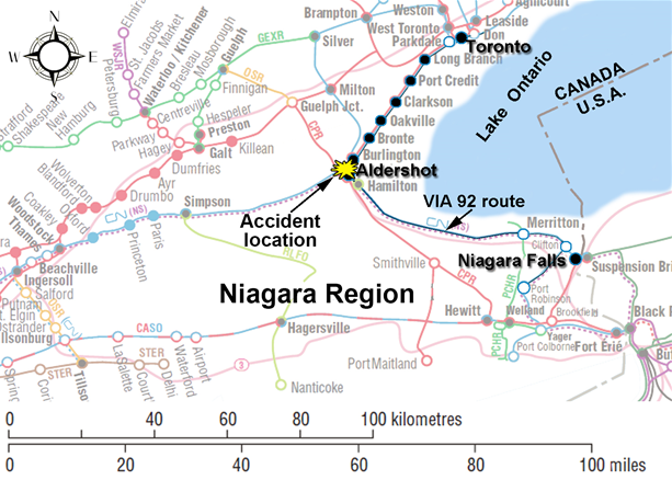
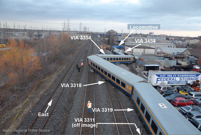
On 26 February 2012, VIA Rail Canada Inc. passenger train No. 92 (VIA 92) was proceeding eastward from Niagara Falls to Toronto, Ontario, on track 2 of the Canadian National Oakville Subdivision near Burlington, Ontario. VIA 92, which was operated by 2 locomotive engineers and a locomotive engineer trainee, was carrying 70 passengers and a VIA service manager. After a stop at the station at Aldershot, Ontario (Mile 34.30), the train departed on track 2. The track switches were lined to route the train from track 2 to track 3, through crossover No. 5 at Mile 33.23, which had an authorized speed of 15 mph. At 1525:43 Eastern Standard Time, VIA 92 entered crossover No. 5 while travelling at about 67 mph. Subsequently, the locomotive and all 5 coaches derailed. The locomotive rolled onto its side and struck the foundation of a building adjacent to the track. The operating crew was fatally injured and 45 people (44 passengers and the service manager) sustained various injuries. The locomotive fuel tank was punctured and approximately 4300 litres of diesel fuel was released.
Ce rapport est également disponible en français.
1.0 Factual information
VIA Rail Canada Inc. (VIA) operates up to 503 trains weekly on 12 500 km of track and serves 450 communities across the country. VIA carries on average 4 million customers annually on its fleet of 396 passenger cars and 74 road locomotives. It operates 159 passenger stations, 4 maintenance facilities and employs approximately 3000 people. While VIA owns 223 km of track, most of the track infrastructure it uses is owned and managed by freight railway companies.
In February 2012, VIA passenger train No. 92 (VIA 92) operated each Saturday and Sunday from Niagara Falls, Ontario, to Toronto, Ontario. On 26 February 2012, VIA 92 was made up of a single head-end locomotive (VIA 6444) and 5 Light, Rapid, Comfortable (LRC) coaches (VIA 3454, VIA 3354, VIA 3318, VIA 3319 and VIA 3311). VIA 92 weighed 389 tons and was 510 feet long. It was last inspected at VIA’s Mimico Maintenance Centre, Ontario, on 25 February 2012, with no defects noted.
There were 70 passengers on board: 41 in the 1st coach, 28 in the 2nd coach and 1 in the 3rd coach. A VIA service manager (SM) was stationed in the 2nd coach. The 4th and 5th coaches were empty. VIA 92 was usually staffed with 2 on-board service personnel. However, on that day, no additional staff was available.
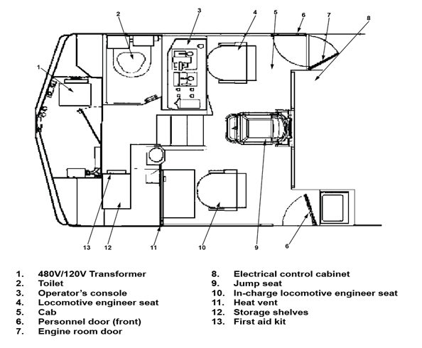
VIA trains are normally operated by 2 qualified locomotive engineers located in the lead locomotive. The operating locomotive engineer (LE) sits at the controls on the right side of the locomotive cab while the in–charge locomotive engineer (ICLE) sits on the left side of the cab and performs the duties of the conductor (see Figure 1).
The LE for VIA 92 had more than 33 years of railway experience, including 28 years as a locomotive engineer. The LE had initially worked as a locomotive engineer for Canadian National (CN) for 24 years before moving to VIA where he had worked for the past 4 years. The ICLE had 34 years of railway experience, including 25 years as a locomotive engineer. The ICLE had initially worked as a locomotive engineer for CN for 21 years before moving to VIA where he had worked for the past 4 years. The LE and ICLE were qualified for their positions, met rest standards and were experienced with the territory. They had worked together as a crew on a regular basis over the previous 16 months.
On this trip, a 3rd operating crew member was in the cab. This crew member was a locomotive engineer trainee who was on this trip as part of VIA familiarization training for trainees. A 3rd person in the cab is usually seated in the jump seat located between the LE and the ICLE. When a trainee accompanies a VIA crew, signal recognition and rules compliance are responsibilities shared equally among all crew members.
The trainee was a qualified locomotive engineer. He had 22 years of railway experience, including 9 years as a locomotive engineer. He had worked as a locomotive engineer for the Ottawa Central Railway (7 years) and for CN (2 years). He had been hired as a trainee by VIA in October 2011. As part of VIA’s locomotive engineer training program, the trainee had completed several assignments between Niagara Falls and Toronto. On some of these assignments, the trainee had been paired with the LE. The trainee met fitness and rest standards.
All 3 operating crew members were based in Toronto. On the day before the accident, the crew had come on duty at 1545 Footnote 1 and had worked westward from Toronto to Niagara Falls on VIA train No. 95 before booking off duty at 2109.
1.1 The accident
On 26 February 2012, the crew came on duty at 1306. Before departing Niagara Falls, the SM provided a pre-departure briefing to the crew. During the briefing, the SM indicated that a wheelchair passenger would be disembarking at Oakville, Ontario. To accommodate this passenger at Oakville, VIA 92 would normally arrive on track 1 adjacent to Oakville Station.
At Niagara Falls, passengers were only seated in the 1st coach (VIA 3454). Prior to departing, the SM made the standard safety announcement using the public address system regarding the safety pamphlet located in the seatback pocket. In accordance with regulatory requirements and VIA procedures, the SM designated and briefed the passengers who were seated near exit windows and side exit doors on emergency procedures.
Passengers who boarded the train at subsequent stations were seated in the 2nd car (VIA 3354), after which the SM once again designated and briefed a number of able-bodied passengers on emergency procedures. During the journey, the doors between the 1st and 2nd cars were left open to make it more convenient to provide service to passengers.
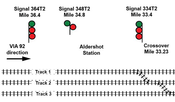
At 1404:40, VIA 92 left Niagara Falls on time destined for Toronto (see Figure 2). VIA 92 was routed on the Grimsby Subdivision from Clifton, Ontario (Mile 2.60), to Hamilton, Ontario (Mile 43.70), where it entered the Oakville Subdivision. Footnote 2 On the Oakville Subdivision, VIA 92 travelled on the north track from Hamilton (Mile 39.30) to Bayview, Ontario (Mile 36.90), where the train was routed eastward on track 2 past Aldershot Station (Mile 34.60) all the way to signal 333T2. This route required VIA 92 to pass controlled signal 364T2 (Mile 36.40) at Snake and advance signal 348T2 (Mile 34.80) at Waterdown on its approach to the Aldershot Station.
Earlier in the day, a CN signals work crew consisting of a signal maintainer and a technician had been dispatched in response to a trouble call reported by the hot box detector (HBD) at Mile 33.10 (approximately 1000 feet east of the King Road crossing). When the signals work crew arrived at the work site, they parked their vehicle north of track 1 and requested a track occupancy permit (TOP) from the CN rail traffic controller (RTC). At 1404:58, the RTC issued a TOP to the signals work crew, which authorized them with exclusive occupancy of track 2 between signal 333T2 (Mile 33.30) Footnote 3 at Aldershot East and signal 324T2 (Mile 32.40) at Burlington West. Once the TOP was issued, the signals work crew walked over to track 2 and commenced with repairs.
At the request of the VIA Oakville Station manager, the RTC had planned to line the route for VIA 92 to arrive at platform 1 to facilitate the disembarkment of the wheelchair passenger. When planning VIA 92’s route east of Aldershot Station, the RTC had the option to cancel the TOP on track 2. However, given the importance of having the HBD repaired, the RTC opted to route VIA 92 around the TOP on track 2. Subsequently, the RTC lined the track switches to
route the train from track 2 to track 3 through crossover No. 5 (Mile 33.23), which was authorized for a speed of 15 mph. The RTC did not communicate the TOP or route change to the VIA 92 crew, nor was there any requirement to do so.
At 1517:19, VIA 92 arrived at Aldershot Station, which was a regular stop. After this stop, the train was normally (that is, over 99 % of the time) routed straight through on track 2. At 1523:26, the trip to Toronto resumed as VIA 92 departed on track 2 and approached controlled signal 334T2 (see Figure 3).
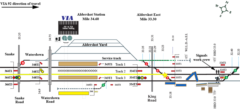
The signals work crew observed VIA 92 accelerate towards them on track 2. Although the area was designated as anti-whistling, VIA 92 sounded the train horn several times. The signals work crew looked eastward at signals 324T1, 324T2 and 324T3 and they confirmed that signal 324T3 was permissive while signals 324T1 and 324T2 both indicated Stop, verifying that they had protection on track 2. However, from their location, they could not observe the aspect on signals 334T1, 334T2 and 334T3 (Mile 33.40), as these signals faced west towards approaching VIA 92. When they recognized that VIA 92 was not slowing down, they moved to a safe location north of track 1.
At 1525:43, VIA 92 entered crossover No. 5 while travelling at about 67 mph. The locomotive (VIA 6444) leaned northward briefly, then derailed and rolled to the south. The locomotive slid down the embankment and struck the concrete foundation of a building adjacent to the right-of-way. The entire rear truck of VIA 6444, including the traction motors, separated from the locomotive, derailed and came to rest approximately 1000 feet east of the locomotive. It was straddling track 3 near the location where the signals work crew was working moments earlier. The signals work crew immediately contacted the RTC and reported the accident. The RTC cancelled all nearby permissive signals to protect the site against other train movements and initiated emergency response protocols.
1.2 Site examination
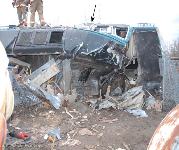
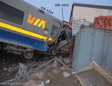
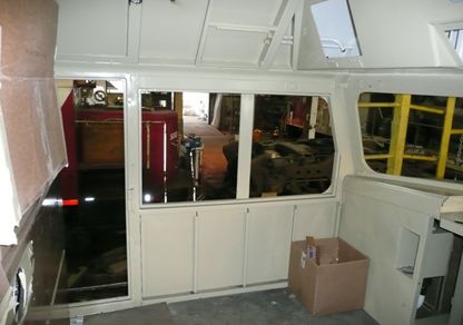
The locomotive and all 5 coaches derailed. In the vicinity of the accident, the tracks are situated at a slightly higher elevation than the surrounding terrain. During the accident, locomotive VIA 6444 and the 1st coach (VIA 3454) slid down the embankment, rolled and came to rest on their sides. The train and its air brake line remained connected and intact. The front locomotive truck was on the side of the embankment, partially attached to the locomotive by cables. The locomotive cab area just above the front nose had struck the foundation of a building adjacent to the track. The building foundation was heavily damaged, while the cab roof had completely collapsed, resulting in extensive damage to the cab interior (see Photo 1).
At the east end of the No. 5 crossover, there were wheel flange impact marks observed on the guard rail and the frog of turnout 5B, indicating that the locomotive wheels had left the north rail near the frog.
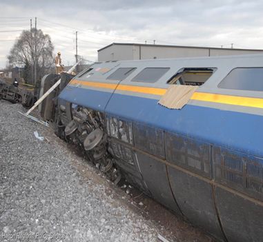
The majority of the passengers were travelling in the first 2 coaches, both of which were heavily damaged. The 2nd coach (VIA 3354) and the 3rd coach (VIA 3318) had jackknifed. The front portion of the 2nd coach had slid down the embankment. The 2nd and 3rd coaches had come to rest foul of track 2. The 4th coach (VIA 3319) and the 5th coach (VIA 3311) remained upright on the right-of-way just south of track 3 and sustained minor impact damage (see Photo 2).
1.3 Emergency response and evacuation
1.3.1 Initial emergency response
At the time of the accident, the SM was in the 2nd coach checking the tickets of passengers who had just boarded the train in Aldershot. Immediately following the accident, the SM conducted visual and verbal checks with passengers in the 2nd car to assess the extent of injuries to the passengers. The SM then tried to contact the locomotive crew with no success, following which the SM made an emergency radio broadcast on the standby channel and then an emergency call on the cell phone to the RTC.
During the derailment, the vestibule between the 1st coach and the 2nd coach broke apart, leaving the respective end doors accessible. The SM exited the 2nd coach through the east-end door and entered the 1st coach through its adjoining partially open door. Together with some able-bodied passengers, the SM provided initial assistance to the passengers. All passengers in the 1st coach remained in the coach until emergency responders arrived. The passengers in the 2nd coach disembarked on their own initiative. While some of these passengers gathered at a meeting point, others departed the site without seeking medical aid.
1.3.2 Subsequent emergency response and evacuation
The accident occurred just east of the King Road level crossing, making the accident site accessible for emergency vehicles, equipment and responders. The Halton Regional Police, Ontario Provincial Police, Emergency Medical Services (EMS) and 3 crews from the Burlington Fire Department arrived at the accident site within minutes.
An incident command post was established for the responders and a unified command structure was put in place to coordinate the activities of the various response agencies. The SM remained and provided assistance throughout the evacuation. CN staff, VIA personnel and other passengers also assisted with rescue and recovery efforts.
Since the 1st coach was on its side with its roof against the building, the available emergency exits (that is, windows and doors) were located on the side of the coach that was facing up (see Photo 3). This presented some initial difficulties and delays for evacuation as the emergency responders had to first gain access to the coach interior. An emergency responder climbed onto the side of the coach and forced entry into the car by breaking the window on the side door. Another emergency responder gained access through the partially open west end door. Once inside the coach, triage of passenger injuries commenced. Tarps were placed over some passengers to protect against falling glass as an emergency exit window was broken to aid with the evacuation.
While the west end door of the 1st coach was partially open, it was bent during the accident and could not fully open (see Photo 4). Subsequently, the door was cut away to aid with the evacuation. Additional ladders were provided to allow emergency responders to gain access to the coach and to allow passengers to evacuate from the coach. It was difficult for many of the passengers and emergency responders to make their way over the seats of the overturned coach to the available exits.
About 20 passengers were evacuated through the windows while the others were evacuated through the west end door. Mobile passengers were first evacuated, followed by those who were trapped and/or more seriously injured. During the evacuation, 4 passengers were carried and removed using backboards and stokes baskets.
To extricate the operating crew, the locomotive roof was cut away and removed. The LE, ICLE and trainee were located in the area of the locomotive cab control stand and had sustained fatal injuries. It was determined that the LE was at the controls at the time of the accident.
The passengers were initially treated at the staging area by EMS. Those who were injured or required more detailed examination were transferred to area hospitals. A total of 13 ambulances and 2 helicopter air ambulances were dispatched to transport the injured.
Since some passengers had already departed the site, it was initially challenging to determine the number of people who were on board. Following a review of VIA records, the number of people (that is, VIA crew, on-board service personnel and passengers) was confirmed and accounted for.
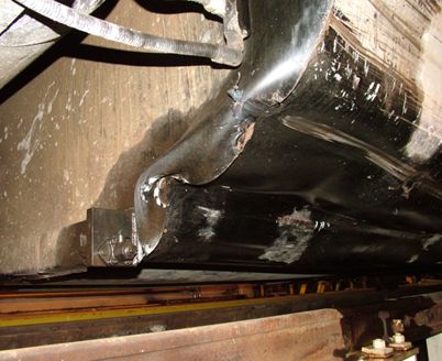
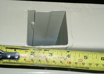
The locomotive fuel tank was dented and punctured along the bottom edge (see Photo 5). Subsequently, approximately 4300 litres of diesel fuel was released. During site clean-up, any fuel that had pooled on the ground was removed by vacuum truck. Contaminated soil was removed and the area backfilled. Monitoring wells were drilled in order to monitor site remediation.
1.4 Injuries
During the accident, the passengers were bounced around and many were ejected or fell out of their seats. A total of 44 passengers and the SM were transported to hospital for various injuries. This included 30 of the 41 passengers in the 1st coach, 13 of the 28 passengers in the 2nd coach and the sole passenger in the 3rd coach.
The most common diagnosis included bruises, lacerations and minor head, neck, shoulder and lower back injuries. Three passengers suffered rib fractures and one passenger sustained a fractured arm. The majority of injuries were sustained by people being ejected or falling out of a seat, being struck by another person, being struck by one of various items that came loose and moved freely within the coach or a combination of these. Seat restraints are not provided for locomotives or passenger coaches nor are they required by regulation.
1.5 Weather
The weather was sunny with clear visibility and the temperature was 0°C.
1.6 Recorded information
Recorded events between Niagara Falls and the accident location are shown in Table 1. Event times have been normalized to coincide with the locomotive event recorder (LER).
| Action | Time | Mile | mph | Brake pipe (psi) | Brake cyl. (psi) | Throt-tle | Bell | Horn | Emerg. brake app. |
|---|---|---|---|---|---|---|---|---|---|
| VIA 92 crew on duty – Niagara Falls | 1306:00 | ||||||||
| VIA 92 departs Niagara Falls | 1404:40 | ||||||||
| TOP issued to CN signal maintainer between signal 333T2 (Aldershot East) and signal 324T2 (Burlington West) | 1404:58 | ||||||||
| VIA 92 departs Grimsby | 1447:39 | ||||||||
| Crossover No. 5 lined from track 2 to track 3 for VIA 92 around CN signals work crew at work | 1512:56 | ||||||||
| VIA 92 passes controlled signal 364T2 (Snake) displaying a Clear to Limited signal (Rule 406) with aspects Y/FG/R | 1514:42 | 36.40 | 41.3 | 98 | 0 | 8 | Y | Y | |
| VIA 92 passes advance signal 348T2 (Waterdown) displaying Clear to Slow signal (Rule 409) with aspects Y /Y | 1516:23 | 34.88 | 53.2 | 90 | 0 | N | |||
| VIA 92 arrives at east end of Aldershot Station on track 2 | 1516:45 | 34.62 | 23.9 | 86 | 13 | 0 | Y | ||
| VIA 92 arrives at Aldershot Station | 1517:19 | 34.50 | 0 | ||||||
| VIA 92 departs Aldershot Station on track 2 | 1523:26 | 1 | 6 | Y | |||||
| VIA 92 activates bell at whistle post | 1525:18 | 33.67 | 58.7 | 96 | 0 | 6 | Y | N | N |
| King Road crossing gates activated | 1525:21 | ||||||||
| LE moves throttle from 6 to 8 | 1525:22 | 33.60 | 59.7 | 96 | 0 | 8 | Y | N | N |
| Horn applied intermittently | 1525:26 | 33.52 | 61.5 | 96 | 0 | 8 | Y | Y | N |
| VIA 92 passes controlled signal 334T2 (Aldershot East) displaying a Slow to Limited signal (Rule 432) with aspects R/FY/FG | 1525:33 | 33.40 | 64.6 | 96 | 0 | 8 | Y | Y | N |
| Horn blast | 1525:37 | 33.32 | 65.5 | 96 | 0 | 8 | Y | Y | N |
| Throttle moved from 8 to 6 | 1525:39 | 33.31 | 66.6 | 96 | 0 | 6 | Y | Y | N |
| Throttle moved from 6 to | 1525:40 | 33.30 | 66.6 | 96 | 0 | 3 | Y | Y | N |
| Horn off | 1525:41 | 33.26 | 66.6 | 96 | 0 | 3 | Y | N | N |
| Second horn blast | 1525:42 | 33.25 | 66.6 | 96 | 0 | 3 | Y | Y | N |
| Locomotive enters No. 5 crossover | 1525:43 | 33.23 | 66.9 | 96 | 0 | 3 | Y | Y | N |
| Throttle moved from 3 to idle (0) and locomotive derails exiting No. 5 crossover | 1525:44 | 33.19 | 66.6 | 96 | 0 | 0 | Y | Y | N |
| Locomotive comes to rest on side | 1525:51 | 33.11 | 0 | 98 | 0 | 0 | Y | N | N |
The locomotive was not equipped to record audio of in-cab conversations between crew members. There were no forward-facing or in-cab video recorders installed on the locomotive. None of the operating crew cell phones were in use at the time of the accident.
1.7 TSB re-enactment
On 04 March 2012, a re-enactment of some of the key events was conducted from the head end of another eastbound VIA passenger train routed through Aldershot Station on track 2. The re-enactment confirmed the following:
- All signals were clearly visible from the locomotive cab throughout the journey.
- It was unlikely that the sun interfered with the crew’s ability to identify the signals.
- Although signal 334T2 was visible from the locomotive cab while stopped at Aldershot Station, the precise signal indication would have been difficult to identify from that distance (approximately 4700 feet).
1.8 Subdivision and track information
Train movements on the Oakville Subdivision are governed by the Centralized Traffic Control System (CTC), as authorized by the Transport Canada (TC)–approved Canadian Rail Operating Rules (CROR) and supervised and directed by an RTC located in Toronto. Train traffic consists of approximately 49 GO Transit commuter trains, 28 freight trains and 18 VIA passenger trains per day. The maximum authorized timetable speed for passenger trains in the area of the accident is 95 mph. On the day of the accident, General Bulletin Order (GBO) 5058 required that speed be reduced to 80 mph on track 2 between Mile 32.00 and Mile 36.40.
In the vicinity of the derailment, the Oakville Subdivision consists of 3 main tracks (that is, tracks 1, 2 and 3). Track 1 is generally used by freight traffic to access CN’s Aldershot yard. Track 3 is normally used by GO Transit commuter train traffic. VIA trains are usually routed through Aldershot on track 2.
Track 1 and track 3 were equipped with 136-pound continuous welded rail. Track 2 consisted of 132-pound continuous welded rail. The rails were laid on 14-inch and 16-inch double-shouldered tie plates fastened to hardwood ties with 2 spikes per plate. The rail was box anchored every second tie. The cribs were full with crushed rock ballast and the drainage was good. The track was inspected in accordance with regulatory and company requirements and was in good condition.
In the vicinity of Mile 33.23, there were 3 crossovers (that is, No. 1, No. 3 and No. 5). These crossovers enabled eastbound and westbound traffic to switch between the Aldershot service track, which accesses the Aldershot Yard, and the 3 main tracks. Each crossover was equipped with a No. 12 turnout at each end. No. 12 turnouts have a maximum authorized speed of 15 mph. These turnouts have 36-foot, 7-inch-long switch points with point rollers that facilitate point movement. Footnote 4 Each crossover was made up of 136-pound running rail and rail bound manganese frogs. The rail was fixed with elastic fasteners to rolled tie plates that were secured to the ties with lag screws. All crossover ties were box anchored, the cribs were full with crushed rock ballast and the drainage was good.
The last inspection of the crossover switches had been conducted by hi-rail on 26 February 2012, the day of and just prior to the accident. A visual walking inspection had been performed for crossover No. 1 and No. 5 on 06 February 2012, with no defects found. A visual walking inspection was performed on crossover No. 3 just after the accident, with no defects found.
The crossovers at this location were primarily used by freight trains entering and leaving the Aldershot Yard. In this area, normal routing for eastbound VIA trains was straight through on track 2. For eastbound VIA trains, crossing over from track 2 to track 1 is usually performed at Burlington West (Mile 32.20) where the crossover consists of the higher speed No. 20 turnouts. The Burlington West crossovers are equipped with No. 20 turnouts, which have a greater distance between the switch point and the frog, allowing for speeds of up to 45 mph.
1.9 Protection for track work
When accessing main line track to perform maintenance or repairs, work crews are required to obtain track protection to protect them from trains. In CTC areas, the work crew can obtain protection to access the track under Rule 842 (Planned Protection) or Rule 849 (TOP):
- In practice, planned protection is usually requested well in advance and is included in a Tabular General Bulletin Order (TGBO), which is issued directly to operating crews.
- TOPs are used for track inspections, for track work performed on short notice or for track work necessitated by emergency situations. In CTC territory, train crews would not be advised of a TOP as they are specifically trained and expected to react to the progression of wayside signal indications as presented along the route.
At CN, small track repairs can also be performed under Safety Watch protection, which requires that 1 member of a 3-person work crew is dedicated to watching for oncoming trains or equipment while the other work crew members perform the work. When a train crew encounters workers on the track under Safety Watch protection, the train crew will typically sound the horn intermittently to capture the work crew's attention with the expectation that they will clear the track. In December 2011, following an accident where a CN Engineering Services employee was struck by a VIA train while performing track work under Safety Watch, CN suspended the use of Safety Watch as a protection method on all class 5 double-track territory (TSB investigation report R11T0161). While CN had communicated this information internally to its engineering personnel, it was not communicated to any other CN or VIA staff, nor was it required to be.
1.10 Centralized traffic control system
CTC is a system to control train movements that employs interconnected track circuits and field signals (that is, controlled, advance, and intermediate signals). Computer displays and controls are installed in the RTC office. The design of the system is such that trains are given a series of progressive track-side signal indications that require train crews to take action based on the signal displayed. In Canada, CTC does not provide any form of automatic enforcement to slow or stop a train if it were to pass a Stop signal or other point of restriction.
When an RTC requests controlled signals for trains, the signal system determines how permissive the signals will be. In the RTC office, track occupancy between controlled locations is displayed on a computer screen. Train movements approaching controlled signals are governed by advance signals that are automatically actuated by the presence of a train located between the controlled signals. The displayed signal indications convey information to train crews that indicates the speed at which they may operate and how far they are permitted to travel. Signal indications also provide protection against certain conditions such as an occupied block, broken rail, or an open switch lined against the movement.
1.11 Canadian rail operating rules and compliance
The TC–approved CROR contain the following definitions with regard to speed:
- LIMITED speed—a speed not exceeding 45 mph;
- MEDIUM speed—a speed not exceeding 30 mph; and
- SLOW speed—a speed not exceeding 15 mph.
Rule 33 (Speed Compliance) states the following:
If speed requirements for their movement are exceeded, crew members must remind one another of such requirements. If no action is then taken, or if the employee controlling the engine is observed to be non-responsive or incapacitated, other crew members must take immediate action to ensure the safety of the movement, including stopping it in emergency if required.
Signal recognition and compliance is governed in part by Rule 34 (Fixed Signal Recognition and Compliance) which states that:
- The crew on the controlling engine of any movement and snow plow foremen must know the indication of each fixed signal (including switches where practicable) before passing it.
- Crew members within physical hearing range must communicate to each other, in a clear and audible manner, the indication by name, of each fixed signal they are required to identify. Each signal affecting their movement must be called out as soon as it is positively identified, but crew members must watch for and promptly communicate and act on any change of indication which may occur.
The following signals/operating signs must be communicated:
- Block and interlocking Footnote 5 signals;
- Rule 42 and 43 signals;
- One mile sign to interlocking;
- One mile sign to hot box detector;
- Stop sign;
- OCS begins sign;
- Red signal between the rails;
- Stop signal displayed by a flagman;
- A switch not properly lined for the movement affected;
- One mile to Cautionary Limit Sign; and
- Cautionary Limit Sign.
- If prompt action is not taken to comply with the requirements of each signal indication affecting their movement, crew members must remind one another of such requirements. If no action is then taken, or if the employee controlling the engine is observed to be incapacitated, other crew members must take immediate action to ensure the safety of the movement, including stopping it in emergency if required.
CROR Rules 405 to 440 govern signals that are utilized in CTC territory. The signal aspects, otherwise known as lights or indications, are differentiated by colour, position of colours, flashing of the lights, or combinations thereof. The signals can be displayed using 1, 2 or 3 lights. Signals are interconnected in series to provide train crews with a progressive indication. Crews are trained on this principle of progression, and in the field, continuously experience it. A “Red” light on top of any aspect is consistently used with rules with a restriction of speed. The signal aspects and associated rules that are relevant to this occurrence are detailed in Table 2.
| Signal aspects displayed | CROR Rules |
|---|---|
 |
Rule 405—Clear Signal—Proceed (at track speed). |
 |
Rule 406—Clear to Limited—Proceed, approaching next signal at LIMITED speed (not exceeding 45 mph). |
 |
Rule 409—Clear to Slow—Proceed, approaching next signal at SLOW speed (not exceeding 15 mph) |
 |
Rule 412—Advance Clear to Limited—Proceed, approaching second signal at LIMITED speed (not exceeding 45 mph) |
 |
Rule 432—Slow to Limited—Proceed, SLOW speed (not exceeding 15 mph) passing signal and through turnouts, approaching next signal at LIMITED speed (not exceeding 45 mph) |
Train crews must be familiar with all signal indications specified in the CROR and are required to control their trains in accordance with these rules. Crew members are also expected to know their operating territory, including the location of individual signals. This knowledge is used to facilitate the detection of signals and to help recognize the presence of an imperfectly displayed signal or absence of a signal.
Perception of signals can be viewed as a 3-step process: detect, discriminate and decide on the aspect displayed. This process can be rapid. When the signals are not obscured or obstructed and there is good visibility, signal perception (that is, recognition) can be accomplished rapidly from relatively long distances. However, signal perception can be affected by the crew's fitness for duty and by perceptual context or mental model.
1.12 Signals displayed for eastbound trains stopping at Aldershot
An eastbound passenger train travelling on track 2 of the Oakville Subdivision, usually with a stop at Aldershot Station (Mile 34.60), would encounter the following signals governing its movement:
- controlled signal 364T2 (Mile 36.40);
- advance signal 348T2 (Mile 34.80); and
- controlled signal 334T2 (Mile 33.40) just before crossover No. 5 at Mile 33.23.
1.12.1 Signal indications displayed when lined through on track 2
When the crossover at Mile 33.23 is lined straight through on track 2, with no speed restrictions in place and permissive signals displayed at Aldershot East (Mile 33.40) and Burlington West (Mile 32. 40), the signal progression is as follows (see Figure 4):
- Signal 364T2 displays a Clear signal (Rule 405) indication with aspects Green over Red over Red (G/R/R)—proceed at track speed;
- Signal 348T2 displays a Clear signal (Rule 405) indication with aspects G/R—proceed at track speed; and
- Signal 334T2 displays a Clear signal (Rule 405) indication with aspects G/R/R—proceed at track speed.
In the 3 months preceding the accident, eastbound VIA 92 arrived at Aldershot Station 27 times. On 26 of these occasions, VIA 92 stopped at the station (that is, 97 % of the time). In addition, VIA trains are routed through the 15 mph crossover at Aldershot East less than 1 % of the time in relation to all crossover moves between Aldershot and Burlington. Based on the scheduled arrivals at Aldershot and the crossover routing decisions, VIA 92 encountered a clear signal indication east of Aldershot Station more than 99 % of the time.
1.12.2 Signal indications displayed when crossover lined from track 2 to track 3
When the crossover at Mile 33.23 is lined to bring a train from track 2 to track 3, the signal progression (see Figure 5) is as follows:
- Signal 364T2 displays a Clear to Limited signal (Rule 406) with aspects Yellow over Flashing Green over Red (Y/FG/R)—proceed, approaching next signal at limited speed (not exceeding 45 mph);
- Signal 348T2 displays a Clear to Slow signal (Rule 409) with aspects Yellow over Yellow (Y/Y)—proceed, approaching next signal at slow speed (not exceeding 15 mph); and
- Signal 334T2 displays a Slow to Limited signal (Rule 432) with aspects Red over Flashing Yellow over Flashing Green (R/FY/FG)—proceed, slow speed (not exceeding 15 mph) passing the signal and through turnouts, approaching next signal at limited speed (not exceeding 45 mph). For eastbound VIA trains between Niagara Falls and Burlington West, this signal combination can only be displayed at Signal 334.

The electronic circuits for Signal 334T2 are such that the signal cannot display an Advance Clear to Limited (Rule 412) aspect (FY/FG/R). However, train crews would only be concerned with and focussed on aspect display and would not know specific details of circuitry.
1.13 Signal testing
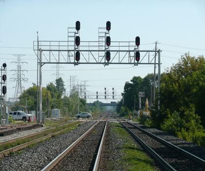
The CTC on the Oakville Subdivision was upgraded from a relay-based logic system to a Geographic Signalling System (GEO) solid-state microprocessor-based system. The field signals at Aldershot East for track 1 (334T1) and track 2 (334T2) were 3-colour light aspect assemblies (Model 20R) while the signal for track 3 (334T3) consisted of a 2-colour light aspect assembly. In each case, the aspect assemblies were positioned one over the other with the top assembly identified as the “A” head, the middle as “B” head and the bottom as “C” head respectively.
Inside each aspect assembly, there are 3 lights positioned one over the other with a total of 9 lights for signals 334T1 and 334T2, and 6 lights for signal 334T3. Incandescent bulbs behind each coloured lens display the proper combination of red, yellow and/or green lights. Only one light in each assembly can be lit at one time. Attempts to activate 2 lights in one assembly would force the signal to its most restrictive state (red). The individual signals face oncoming traffic and are mounted on an aluminium gantry located above the right-of-way, positioned directly over the track that they govern (see Photo 6).
Immediately following the accident, the wayside signals governing VIA 92's movement approaching Aldershot East (Mile 33.30) were inspected and tested by CN Signals & Communications (S&C) technicians. All signal control cables and underground control circuits were tested for short circuits. The aspect lamp voltages were taken and battery ground tests were conducted. Through these tests, the signal system was determined to be functioning in accordance with CROR, CN Signals & Communications General Instructions, Code and Practices specifications, and approved plans.
To further verify the signalling system, the TSB contracted an independent signal consultant to inspect the signals and review all related data. The consultant confirmed that
- the signal hardware and software had been installed according to plan;
- the signalling system had worked as designed; and
- the signalling system complied with established block and interlocking signal rules described in the CROR.
On 08 March 2012, CN technicians (in the presence of TSB investigators and a consultant) performed procedures CN GI-309 (Test Ground Resistance) and CN Gl-312 (Testing Wire and Cable Insulation Resistance). These tests were performed on the wiring between the signal bungalow and the 3-colour light aspect assemblies of signal 334T2. The results were within tolerance and the integrity of the wiring was confirmed. The inside of the signal heads were also inspected and did not exhibit any damage or corrosion. Each of the aspects for signal 334T2 was equipped with light bulbs (part number RR-10128-SF) manufactured by GEMS. The measured voltage for each of the lights was within the accepted standards. In addition, CN performed a second download of the data stored in the signal bungalow that re-verified the data previously downloaded.
The signal inspection and testing concluded that
- on 26 February 2012, immediately before the accident, the crossover at Mile 33.23 was lined to bring VIA 92 from track 2 to track 3.
- the following wayside signals were displayed governing the route of VIA 92 as it approached Aldershot East (Mile 33.30):
- Signal 364T2 displayed a Clear to Limited signal (Rule 406) with aspects Y/FG/R;
- Signal 348T2 displayed a Clear to Slow signal (Rule 409) with aspects Y/Y; and
- Signal 334T2 displayed a Slow to Limited signal (Rule 432) with aspects R/FY/FG.
1.14 VIA locomotive engineer training
All VIA locomotive engineers undergo in-class refresher training 1 day per year, which includes a review of the signal rules. They are also tested on signal rules once every 3 years and must obtain a score of 100 % to maintain their VIA qualification. Although the test does not include all signal rules, the questions are randomly selected, requiring the locomotive engineer to be prepared for all the rules.
VIA provides its locomotive engineers with self-training aids for signal rules. VIA locomotive engineers also continually exercise signal rules recognition as a crew while performing their duties and during periodic VIA efficiency testing.
For operating crews, VIA hires either qualified locomotive engineers (trainees), certified locomotive engineers who need to complete their qualification or internal employees as student locomotive engineers. In the Toronto Terminal, the training period for qualified locomotive engineers is normally from 4 to 8 months. During training, signal rules are reviewed in detail. A trainee must achieve a score of 100 % on the signal rules test in order to pass.
In this case, the trainee was in the final stage of training and was within a few weeks of fully qualifying, after having progressed at a relatively fast pace. The trainee had already achieved 100 % on the signal rules test. The final stage of training consisted of familiarization assignments in the cab. During this type of training, the trainee would occasionally operate the locomotive under the supervision of the operating crew.
1.15 Situational awareness and mental models during train operation
Situational awareness (SA) in relation to operational matters refers to the operator knowing what is happening in the immediate environment. There are 3 stages of SA: Footnote 6
- “Perception” refers to the recognition that new unambiguous cues exist.
- “Comprehension” refers to understanding the order of importance of the new cues.
- “Projection” refers to the ability to forecast future events based on information given.
A train crew's SA comes from various information sources. These can include radio transmissions, signal indications, in-cab displays, observation of the track, environmental conditions and written information. Railway rules and operating instructions also affect SA. For example, CROR and General Operating Instructions (GOI) provide information that operating crews are required to use. When operating a train, decisions and actions greatly depend on the crew's assessment and understanding of the operational situation.
The overall understanding of a situation is based on experience, knowledge and perception of external cues resulting in a mental model. It is difficult to alter a mental model once developed, particularly in a short period of time. To change one's thinking, the existing model must be superseded by another. New information must be provided that is sufficiently noticeable and compelling to result in an update of the mental model
Accurate SA is highly dependent on switching attention between different information sources during which people can get trapped in a phenomenon called attention narrowing or tunnelling. When succumbing to tunnelling, they lock in on certain cues or features of the environment they are trying to process, and will either intentionally or inadvertently drop their scanning behaviour. In these cases, people will believe that this limited focus is sufficient because the situation they are attending to is most important in their minds. In other cases, people can fixate on certain information and forget to reinstate their information scan. Either situation can result in their SA being inaccurate. The reality is that keeping at least a high-level
understanding of what is happening across the board is a prerequisite to being able to know that certain factors are indeed still more important than others. Otherwise, it is often the neglected aspects of the situation that prove to be the fatal factors in loss of SA.Footnote 7
1.16 Additional defences for signal indications
With respect to train operations, the railways and TC have based their safety philosophy on a cornerstone of strict rules compliance. While regulatory compliance is necessary for accident prevention in transportation, regulatory compliance alone is not sufficient to maintain safety in a complex transportation system. Organizations that place excessive reliance on strict regulatory compliance tend to believe that the safety rules they have developed are invulnerable to human error. A rule-book culture can produce an attitude that assumes that all accidents are the result of individual failures to follow the rules. Unfortunately, in a complex system such as transportation, even the most rigorous set of rules will not cover every contingency and interpretation by individuals will be required to cover unanticipated situations. Even the most motivated and experienced employees are subject to the normal slips, lapses and mistakes that characterize human behaviour. The defence-in-depth philosophy advocated by safety specialists for complex systems seeks multiple and diverse lines of defence to mitigate the risks of normal human errors.
For many years, the railway industry in Canada has relied on crew compliance with wayside track signals that provide train crews with a series of signal indications requiring crew actions relative to the signals displayed. In this context, train crews are expected to react to the progression of wayside signal indications. RTCs will minimize the amount of information passed on to operating crews to reduce the risk of anticipation that can result in crew expectation bias related to the signals ahead. The level of safety afforded by wayside signal systems has not advanced significantly beyond their original design, which dates back over 100 years. However, high-speed passenger trains now share track with freight trains and the overall pace of rail transportation has increased since wayside signals were first introduced.
Following the investigation into the 1998 train collision involving 2 Canadian Pacific Railway (CPR) trains near Notch Hill, British Columbia (TSB investigation report R98V0148), the Board determined that backup safety defences for signal indications were inadequate. The Board recommended that
The Department of Transport and the railway industry implement additional backup safety defences to help ensure that signal indications are consistently recognized and followed.
Transportation Safety Recommendation R00-04 (issued February 2001)
Action to date on the deficiency has resulted in procedural improvements implemented by CPR with its crew resource management practices. While there has been some safety benefit, administrative or procedural defences are not always adequate to protect against an operating crew misinterpreting and/or misperceiving wayside signal indications. TC and the railways are exploring the potential for current locomotive fleet computer systems to include signal recognition and air brake control capabilities. However, to date, there has been no formal strategy developed to adapt either emerging technology or existing on-board computer systems to provide fail-safe physical train control defences. Therefore, the Board reassessed the response to Recommendation R00-04 to remain Satisfactory in Part.
1.17 TSB investigations involving misinterpretation of rules or signals
Since 2007, the TSB has conducted 5 investigations into train collisions or derailments where the misinterpretation and/or misperception of wayside signal indications by an operating crew was a cause or contributing factor. These investigations include
- R11E0063 (Bailey) – On 23 June 2011 at approximately 0625 Mountain Daylight Time, CN freight train Q10131-21, proceeding westward at 25 mph on the Wainwright Subdivision, collided with the tail end of CN freight train A41751-23 at Mile 262.30. As a result of the collision, 2 intermodal flat cars derailed (3 car bodies) and locomotive CN 2234 was damaged.
- R10Q0011 (Saint-Charles-de-Bellechasse) – On 25 February 2010, VIA train No. 15 (VIA 15) was proceeding westward from Halifax, Nova Scotia, to Montréal, Quebec. At approximately 0425 Eastern Standard Time near Saint-Charles-de-Bellechasse, Quebec (Mile 100.78 of the CN Montmagny Subdivision), the train entered a siding switch, which had an authorized speed of 15 mph, while travelling at approximately 64 mph. Two locomotives and 6 passenger cars derailed. Two locomotive engineers and 5 passengers were injured. In this accident, advance knowledge of the location of an opposing CN train influenced the crew's expectation that they would not be taking the siding.
- R10V0038 (KC Junction) – On 03 March 2010 at about 1410 Pacific Standard Time, CPR train 300-02, operating eastward on the north track of the Mountain Subdivision approaching KC Junction, British Columbia, side collided with westbound CPR train 671-037 when it was departing Golden from the north track through the crossovers onto the south track. As a result of the collision, 3 locomotives and 26 cars derailed. The crew members of train 300-02 were transported to hospital for observation.
- R09V0230 (Redgrave) – On 30 October 2009 at about 2225 Pacific Daylight Time, CPR train 355-429, operating westward on the signalled siding track at Redgrave, British Columbia (Mountain Subdivision), side collided with eastbound CPR train 110-30 that had stopped on the main track. As a result of the collision, 2 locomotives and 6 cars derailed.
- R07E0129 (Peers) – On 27 October 2007 at 0505 Mountain Daylight Time, the crew on CN train A41751-26 (train 417), operating westward on the main track of the Edson Subdivision, initiated an emergency brake application approximately 475 feet from a stop signal at the west end of Peers, Alberta. The train was unable to stop prior to passing the signal and collided with eastbound CN train M34251-26 (train 342) that was entering the siding. As a result of the collision, train 417's locomotives and 22 cars derailed and 5 cars on train 342 derailed.
1.18 Train control systems that protect against signal misinterpretation
The rail industry has developed technology to address the risk of misinterpreting or not following signal indications. The technologies currently in use include
- Proximity detection
- Cab signalling systems
- Positive train control
- Automatic Trainstop at Toronto Transit Commission (TTC)
- Computer-based train control on Scarborough Light Rail System (TTC)
- Speed control system at TTC
- Train control systems at Amtrak
1.18.1 Proximity detection
A proximity detection device was developed and implemented by Quebec North Shore & Labrador Railway after a 1996 collision involving 2 of its trains (TSB investigation report R96Q0050). The proximity detection device is designed to trigger penalty braking if a train crew or track unit operator does not acknowledge the alert warning status when they come within a predetermined distance of another movement. Except for limited trials, no similar systems have been implemented on other Canadian railways.
1.18.2 Cab-signalling systems
Cab signalling is a communications system that provides track status information to a display device mounted inside the locomotive cab. The simplest systems display the wayside signal indication while more advanced systems also display maximum permissible speeds. The cab signalling system can be combined with automatic train control (ATC) to warn operating crews of their proximity to points of restriction and to initiate enforcement action to slow or stop a train.Footnote 8Cab signals can reduce the risk of signal recognition errors.
In 1922, the United States Interstate Commerce Commission (ICC) made a ruling that required United States railroads to install some form of ATC in one full passenger division by 1925. In response to this ruling, the first cab signalling systems were developed and put into use in the United States. Footnote 9 Cab signalling systems have evolved and remain in use in some United States passenger train corridors. In Canada, there is currently no cab signalling system in use by freight or passenger railways.
1.18.3 Positive train control
Positive train control (PTC) is an emerging train control technology that is designed to prevent
- train-to-train collisions,
- overspeed derailments,
- incursions into work zone limits, and
- movement of a train through a switch left in the wrong position.
If the operating crew does not initiate an adequate response, the PTC system would automatically slow or stop the train.
In the United States, the PTC technology has been under development for many years. The following is a summary of the major events that have influenced the development of PTC:
- Following the investigation of the head-on collision of 2 Penn Central commuter trains near Darien, Connecticut, United States, on 20 August 1969, in which 4 people were killed and 45 people were injured, the United States National Transportation Safety Board (NTSB) recommended that the United States Department of Transportation (DOT) Federal Railroad Administration (FRA) study the feasibility of requiring a form of automatic train control system to protect against train operator error in order to prevent train collisions.
- After the rear-end collision involving a Boston and Maine Corporation commuter train and a Consolidated Rail Corporation (Conrail) freight train on 07 May 1986, in which 153 people were injured, the NTSB recommended that the FRA publish standards requiring the installation and operation of a train control system that would provide for positive train separation (NTSB Recommendation R-87-16, May 1987).
- In 1990, when the NTSB first established its Most Wanted List of transportation safety improvements, it included the issue of positive train separation, which was later changed to PTC.
- In September 1997, the FRA asked its Railway Safety Advisory Committee (RSAC) to address the issue of PTC. A PTC Working Group, which included TC, was formed. In 1999, the working group submitted its report defining the core functions of PTC.
- In 2002, the need for safety improvements was again highlighted when a freight train and a commuter train collided head on in Placentia, California.
- On 12 September 2008, a collision between a Metrolink passenger train and a Union Pacific freight train in California resulted in 25 fatalities and more than 135 serious injuries.
The Metrolink accident prompted the passage of the Rail Safety Improvement Act of 2008, which mandated that, by 2015, PTC be installed on many higher risk rail lines in the United States. However, due to a number of technical challenges, it is anticipated that the United States implementation of PTC will be delayed beyond the 31 December 2015 deadline.
In Canada, there are currently no PTC systems in use by freight or passenger railways and there are no planned PTC installations. Any application of PTC in Canada likely would not occur for a number of years after the United States implementation is complete. However, to meet the PTC requirements for United States operations, both CN and CPR have PTC implementation plans:
- As part of CPR's implementation plan, 460 high horsepower (HHP) locomotives and 110 road and yard switchers will be equipped with the required on-board systems. CPR will install PTC on approximately 1660 miles of track in the United States.
- As part of CN's PTC implementation plan, 820 HHP locomotives and 180 low horsepower locomotives will be equipped with the required on-board systems. CN will install PTC on approximately 3720 route miles of track in the United States.
For both CN and CPR, the PTC system will be based on the Interoperable Electronic Train Management System (I-ETMS). CN will install it on 41 subdivisions, and CPR will install it on 17 subdivisions, corresponding respectively to 62 % and 89 % of their total United States route miles (excluding yard limits). The I-ETMS is a locomotive-centric, train control system that uses a combination of locomotive, office and wayside data that are integrated using a radio network. This system provides the following functions:
- alert train crews to pending authority and speed limit violations, including passing a stop signal;
- stop trains before exceeding authority and speed limits, including signals at stop;
- interrogate upcoming wayside signals, and switches, in a train route when operating in I-ETMS territory; and
- protect work zone limits by enforcing compliance with work zone restrictions.
1.18.4 Automatic trainstop at Toronto Transit Commission
The TTC fixed block signalling system controls subway train movements, including the speed of trains, with a device known as the Automatic Trainstop (Trainstop). This system has been widely used in commuter rail systems throughout North America since the 1930s to ensure compliance with stop indications. Trainstop automatically stops a train when the signal aspect and the operating rule prohibit such a movement. The system operates by mechanical engagement of a trip arm, which is attached adjacent to the field side of the rail. On each train, there is a trip valve that is connected directly to the train air brake system.
When the signal is clear, the trip arm lowers so that trains can pass at will. When the signal requires a stop (that is, red aspect) the wayside trip arm is raised to the danger position so that it engages the trip valve and activates an emergency brake application.
1.18.5 Computer-based train control on Scarborough light rail system (TTC)
The TTC Scarborough Light Rail System utilizes a computer-based train control system that has been in place since the mid-1980s. A similar system is used to operate the “Skytrain” in Vancouver, British Columbia.
The computer-based train control system on the Scarborough light rail line is a moving block train control system where wayside equipment and train-mounted equipment exchange information and commands through a continuous inductive loop wire laid in the track bed. There are on-board computers on each train and a master computer at a fixed location. There is continuous communication on the loop cable between the on-board train computers and the master computer. The on-board computer continually transmits train position and speed, computes braking distances and ensures that the train remains within the speed limits imposed by the master computer. This data exchange ensures safe train spacing, safe braking, continuous monitoring and speed control of all trains.
1.18.6 Speed control system at Toronto Transit Commission
TTC has recently installed a speed control system (SCS) on its Yonge/University/Spadina subway line. The SCS is an overlay on TTC's conventional relay logic signalling system. The main function of the SCS is to supervise and enforce permitted speed limits, restricted speeds, reduced speed zones and signal adherence. Electronic transponders are installed at track level throughout the system and yards. A train on-board controller detects the wayside transponders, determines train location and then calibrates wheel revolutions for exact positioning.
The on-board controller compares the transponder information with track and system information stored in its memory after which it calculates the location of the train and controls train speed for that area of track. The speed is displayed on the train driver's console and an audible alarm sounds if an overspeed occurs. If the train driver does not respond appropriately to an overspeed or a signal indication, the SCS engages the train brakes.
1.18.7 Train control systems at Amtrak
In May 1971, the United States National Railroad Passenger Corporation (Amtrak) was formed and Amtrak has been managing the United States rail passenger service since that time. The TSB met with Amtrak to obtain an overview of the train control systems that are currently in place on its Northeast Corridor (NEC). In the NEC, Amtrak operates a fully electrified railway using overhead catenary wires to power its locomotives. Conventional diesel motive power equipment can also operate on the same tracks provided that the equipment is also equipped with in-cab signals and ATC. Amtrak trains on the NEC are operated by a single locomotive engineer in the locomotive cab.
The NEC comprises about 430 track miles from Boston, Massachusetts, to New York City, New York, and to Washington, DC, with branches serving other cities. The NEC is the busiest passenger rail line in the United States by ridership and service frequency with over 300 trains on Amtrak–controlled segments each weekday. Presently, about 75 % of paid travellers between New York City and Washington travel by train. The NEC train traffic includes
- conventional freight trains powered by diesel locomotives operated by CSX and the Providence and Wooster railways that travel at speeds between 30 and 50 mph,
- Amtrak regional trains that travel at speeds between 110 and 135 mph,
- various commuter trains that travel at speeds up to 135 mph, and
- Amtrak Acela Express high-speed trains that travel at speeds up to 150 mph.
The following list summarizes various events that led to the development and implementation of train control systems on the NEC:
- Since 1938, passenger locomotives that operated on the NEC have been equipped with cab signals that display wayside signals in the locomotive cab to the operating crew.
- On 17 June 1947, the United States ICC ordered (Order No. 29543) that cab signals, automatic train stop or ATC be installed on any line on which train speed would exceed 79 mph.
- Since 1952, passenger locomotives were also equipped with a fully functioning ATC system. The ATC system incorporates cab signals and speed control with a penalty brake. If a train operator does not respond to the signal displayed in the cab, the system automatically applies a penalty brake application to control the train speed in accordance with the signal displayed.
- On 04 January 1987, a train collision occurred near Baltimore, Maryland, United States. While proceeding at about 108 mph (174 km/h), the Amtrak passenger train collided with a Conrail locomotive consist, which had fouled the mainline. As a result of the accident, the Amtrak locomotive engineer, a lounge car attendant and 14 passengers were fatally injured. Since 1988, and as directed by the FRA, all trains that operate on the NEC have been equipped with cab signals and ATC.
- Since 2000, in certain areas of the NEC where Amtrak's high-speed Acela trains operate, ATC has been supplemented by Amtrak's Advanced Civil Speed Enforcement System (ACSES). ACSES is a transponder-based overlay system that operates in parallel with ATC on Amtrak trains. The transponders are passive devices that require no energy source other than that of a passing train. They contain basic information and are permanently fastened between the rails of a track on top of the ties, in sets of at least 2.
- ACSES uses transponder information, data radios and train speed information to perform calculations and enforce permanent and temporary speed limits as well as positive stops at interlockings and signals displaying stop indications. ACSES was initially installed between New Haven, Connecticut, and Boston, Massachusetts (180 route miles), and on 2 sections of the NEC (about 50 route miles) between New York and Washington. Transponders are currently being installed throughout the remainder of the NEC (200 miles). It is expected that, by 2014, the entire NEC will be fully equipped with both ATC and ACSES for all Amtrak trains.
- Although Amtrak ATC and ACSES operate as independent systems, in combination, they each function as part of Amtrak's PTC system. The systems share a common aspect display unit in the cab. ATC and ACSES can continue to operate providing enforcement functions in the event that the other system fails. When operating in parallel, both systems provide speed enforcement with the more restrictive speed prevailing. In February 2010, the FRA approved the Amtrak system as a fully functioning PTC system.
1.19 Amtrak locomotive simulators
The TSB operated 2 Amtrak train simulators that were programmed for the NEC. The signal and rule system utilized by Amtrak differs slightly from the CROR and Canadian CTC. In particular, slow speed can be 20 to 30 mph while the CROR defines slow speed as 15 mph. However, the fundamentals of train control using progressive signal indications remain the same. Amtrak signal blocks Footnote 10 have been shortened to approximately 1 mile to accommodate increased train speeds and traffic volume. In comparison, the distance between controlled signal locations in the vicinity of the accident is about 3 miles.
One simulator was set up similar to an Acela cab equipped with cab signalling, ATC and ACSES. In addition to adherence to signals, ACSES also enforces speed restrictions and upcoming stops. If there is no appropriate action or response from a locomotive engineer, ACSES slows the train for a slow order and stops the train before it arrives at a stop indication. During a simulation, attempts were made to speed past a restricting signal indication and a stop indication. In both cases, ACSES prevented actions that were contrary to the signal indications displayed.
Another simulator was set up similar to the VIA 92 General Motors (GM) F40PH-2D locomotive cab. It was also equipped with cab signalling and ATC (speed enforcement and penalty brake). In the first simulation, the ATC enforced the speed in the block occupied by the train. However, the next block was not displayed or enforced. When a signal indication displayed red, the stop was enforced after the signal was passed. While the signal that displayed a stop indication could be passed, the speed approaching a stop indication was reduced so the signal was passed at a much slower speed. After the train passed the signal, the system enforced the full stop.
An operations re-enactment was conducted on the simulator that was set up similar to the VIA 92 GM F40PH-2D locomotive cab. Using existing Amtrak cab signalling, ATC, operating rules and signal aspects, a simulation was programmed with a progression of signals similar to those displayed for VIA 92’s approach to Aldershot East. The simulation demonstrated the functionality of a cab signalling system interfaced with ATC. The following events occurred in the simulation:
- the signals in advance of Aldershot Station limited the train speed within the block to 20 to 30 mph;
- after stopping at Aldershot Station, the train was limited to 20 to 30 mph upon departure (depending on aspect displayed) up to signal 334T2 just before crossover No. 5; and
- when the train passed signal 334T2, the ATC enforced a further speed reduction.
1.20 Amtrak in-cab voice recording
All Amtrak Acela locomotive cabs are equipped with in-cab voice recording interfaced with the LER. The voice recorder operates throughout the journey on a loop that records 20 minutes of in-cab activity and continually overwrites the tape.
Voice recordings are automatically saved when certain events are triggered. The recordings are saved when the locomotive sustains an impact of 3 Gs (1 G = force of gravity) Footnote 11 or more or the locomotive lists at least 20° off centre. When a triggering event occurs, the system automatically saves the last 20 minutes of recorded cab activity in the LER.
1.21 Train control systems in other countries
Various forms of ATC have been operational in other countries for decades. These systems usually include some form of ground-based system and on-board system that interconnect to provide the functionality of an ATC system. For example:
- An automatic warning system (AWS) was introduced in the United Kingdom in 1956 and has transitioned to what is known today as the train protection and warning system (TPWS).
- France, Germany and Italy have implemented full automatic train protection (ATP), which is similar to ATC, for dedicated high-speed rail lines. Europe is currently transitioning to one ATP standard called the European Rail Traffic Management System (ERTMS). ERTMS is well evolved as a result of many years of European ATP experience and development.
- Danish and Swedish railways use sophisticated ATC technologies to enforce signal compliance and speed restrictions while Tranzrail in New Zealand uses a vigilance device that sounds an alarm and stops the train if the train driver fails to respond.Footnote 12
- Some railways in other non-European countries such as Australia, India and China operate with functioning ATC systems. In particular, the high-speed railway lines in the People’s Republic of China operate using the Chinese Train Control System (CTCS), which is similar to the ERTMS.
To date, no major passenger (VIA) or freight railway (CN or CPR) in Canada has implemented any form of automatic train control.
1.22 VIA 92 locomotive and coach information
Information regarding rolling stock involved in the accident is contained in Table 3 below.
| Rolling stock | VIA no. | Builder | Model | Type | Year built |
|---|---|---|---|---|---|
| Locomotive | 6444 | GM Electro-Motive Division (EMD | F40PH-2 (GPA-30h) | Wide-nose locomotive | 1989 |
| 1st coach | 3454 | Bombardier | LRC | VIA 1 club car | 1984 |
| 2nd coach | 3354 | Bombardier | LRC | Coach | 1983 |
| 3rd coach | 3318 | Bombardier | LRC | Coach | 1980 |
| 4th coach | 3319 | Bombardier | LRC | Coach | 1980 |
| 5th coach | 3311 | Bombardier | LRC | Coach | 1979 |
1.23 VIA locomotive rebuild
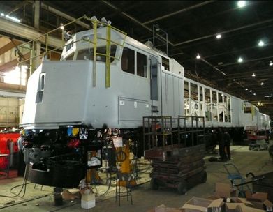
VIA 6444 was manufactured in 1989 and was 1 of 53 GM F40PH-2D locomotives delivered to VIA between 1986 and 1990. This wide-nose locomotive is configured with the short hood leading. The locomotive body is fully enclosed and has internal walkways for access to the engine compartment. These 4-axle, 3000 horsepower diesel-electric locomotives were built for passenger service.
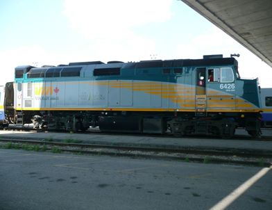
In 2007, VIA contracted CAD Industries in Montréal, Quebec, and commenced a rebuild program for the GM F40PH-2D fleet during which each locomotive was stripped down to its frame (see Photo 7) and rebuilt from top to bottom (see Photo 8). The rebuild work for VIA 6444 was completed in December 2009 and it was returned to service.
The GM F40PH-2D locomotives were rebuilt with technical upgrades for improved operating efficiencies and reliability. These upgrades included improvements to the trucks, to the locomotive motor and to the generator that powers the passenger cars. In addition, a new crashworthy LER was installed in accordance with TC–approved Railway Locomotive Inspection and Safety Rules (Locomotive Safety Rules) and the cab roof structure was modified to accommodate an air conditioner. The original fuel tanks were repaired if necessary, painted and re-installed.
The front nose section of the GM F40PH-2D locomotive contains 2 substantial collision posts to protect against frontal collision. In comparison, the roof structure and cab sides were constructed with various configurations of light gauge steel (see Photo 9). The roof frame structure consisted of a number of steel U-channels that were fabricated into a 2½-inch square tube (see see Photo 10). The wall thickness of the tube was 0.120 inch (just under 1/8 inch) while the roof sheeting was 0.135 inch thick (just over 1/8 inch). There was no significant corner post structure and no roof reinforcement.
During the rebuild, there was no structural upgrade in the area of the cab to protect against rollover or impact. This rebuild did not include the structural requirements outlined in Part II of the Locomotive Safety Rules and nor was it required. Once rebuilt, the service life of these locomotives can extend up to 40 years or longer if rebuilt again in the future. Such rebuild programs are not uncommon in the rail industry.
The rebuild did not include the installation of an in-cab voice recorder. In TSB investigation report R99T0017, the Board recommended that:
The Department of Transport, in conjunction with the railway industry, establish comprehensive national standards for locomotive data recorders that include a requirement for an on-board cab voice recording interfaced with on-board communications systems.
Transportation Safety Recommendation R03-02 (issued July 2003)
Considering that TC had implemented partial performance specifications for data collection, the Board assessed TC’s response as Satisfactory in Part. However, the Board remains concerned that the principle of voice recordings as a valuable safety tool has not been implemented.
1.24 Regulatory requirements for locomotive crashworthiness
VIA's F40PH-2D locomotives were originally built in accordance with the standard in place during the 1980s, which was Canadian Transport Commission General Order 0-21, otherwise known as the Railway Motive Power Equipment Regulations. The regulations contained no specific requirements relating to locomotive cab crashworthiness, as such standards had not yet been established. The Canadian Transport Commission was replaced by Transport Canada (Rail Safety) in the early 1990s. General Order 0-21 remained in place until 1997 when the TC–approved Locomotive Safety Rules were implemented.
1.24.1 Locomotive safety rules
The Locomotive Safety Rules established in 1997 outlined the minimum criteria for locomotive design and crashworthiness. However, nothing precluded a railway company from specifying a more robust design.
Part II, Locomotive Design Requirements, Section 10, General Design, indicates the following:
10.1The locomotive shall be designed and constructed to provide for safe operation and protection of the operating crews and property from accidents caused by functional failure of locomotives.10.2New locomotives shall be designed and constructed as a minimum in accordance with the “Association of American Railroads Manual of Standards and Recommended Practices” (S-580) or to an equivalent standard to provide for safe operation and for the protection of operating crews, and property from accidents caused by functional failure of locomotives.
In January 2006, the Locomotive Safety Rules were modified to include separate crashworthiness standards for freight and passenger locomotives. This remains unchanged in the present version of the Locomotive Safety Rules dated February 2010.
10.2 (a) Freight Locomotives
New locomotives shall be designed and constructed as a minimum in accordance with the latest revision of the “Association of American Railroads Manual of Standards and Recommended Practices” (S-580) or to an equivalent standard
[....]10.2 (b) Passenger Locomotives
New locomotives shall be designed and constructed as a minimum in accordance with the latest revision of the “American Public Transit Association” (APTA), the Association of American Railroads Manual of Standards and Recommended Practices or equivalent standard.
By reference, the applicable APTA standard is 11.APTA SS-C&S-034-99, Rev. 2, Standard for the Design and Construction of Passenger Railroad Rolling Stock.
In the United States, parts 229 and 238 of the FRA Title 49 of the Code of Federal Regulations established the final rule on locomotive crashworthiness in 2006, with most provisions taking effect 01 January 2009. Section 229.203 requires that locomotives manufactured or remanufactured in the United States on or after 01 January 2009 must meet crashworthiness standards. By reference, the FRA final rule also incorporates the latest revision of AAR Standard S-580.
1.24.2 Locomotive crashworthiness standards – Association of American Railroads Manual of Standards and Recommended Practices Standard S-580
AAR Standard S-580 provides requirements applicable to all new road-type locomotives, except for passenger-occupied vehicles, manufactured after 31 December 2008 (from 01 January 2009 on) for use on standard gauge track on North American railroads in revenue freight service or in commuter/passenger service. A summary of locomotives operated by major Canadian passenger and freight railways built prior to 01 January 2009 is provided in Table 4 below.
| Railway | Number of road locomotives | Number built prior to 2009 | Percentage built prior to 2009 |
|---|---|---|---|
| VIA | 74 | 74 | 100 |
| CN | 1393 (North America) | 1208 | 87 |
| CPR | 1539 (North America) | 1448 | 94 |
The primary purpose of AAR Standard S-580 is to minimize the potential for injuries and fatalities to train crews and others involved in the transportation of freight and passengers. This standard provides design requirements for locomotives with improved crashworthiness features. The design requirements were developed as enhancements to the original AAR Standard S-580 (1989).
Locomotives used in freight service and VIA passenger service in Canada are primarily of 2 designs. They are either a wide-nose locomotive design (North American cab) or narrow-nose locomotive design. A wide-nose locomotive has a short hood leading that spans the full width of the locomotive while a narrow-nose locomotive has a short hood leading that spans substantially less than the full width of the locomotive.
AAR Standard S-580 specifies that wide-nose locomotives must have substantial collision posts at the front of the locomotive to protect against frontal collisions. It states in part that
- Each locomotive must be equipped with at least two collision posts or equivalent structures that are located as follows:
- at the approximate 1/3 points across the width of the locomotive
- in their entirety forward of the seating position of any crew person
- must extend in height to a distance 24 in. above the finished cab floor
Each collision post must be continuously attached/welded to the front skin and roof of the short hood
Each collision post must withstand the following loads without exceeding the ultimate strength of the posts and their attachments to the underframe:
- A 750,000-lb load applied over the bottom 10 % of the overall height of the collision post at the base […], at any angle in the horizontal plane in the range of ±15° of the longitudinal axis of the locomotive
- A 500,000-lb load applied over an area, the width of the post structure and the height of 10 % of the overall height of the post on each collision post, centered at a height 30 in. above the top of the underframe […], at any angle in the horizontal plane in the range of ±15° of the longitudinal axis of the locomotive.
Each main diesel fuel tank […] must meet the requirements of MSRP [Manual of Standards and Recommended Practices] Standard S-5506, “Performance Requirements for Diesel Electric Locomotive Fuel Tanks,” latest revision.
The short hood must be capable of supporting a longitudinal load of 400,000 lb. applied to the front of the short hood in the upper corner over an area that is 12 in. wide starting 30 in. above the top of the deck and extending to the nose cab roof sheet without exceeding ultimate strength [....]
[a truck attachment that secures each truck to the frame of the locomotive.] Attachment of each truck to the frame must withstand an equivalent ultimate shear value of 250,000 lb from the longitudinal to lateral, inclusive.
Cab corner posts and rollover protection are not required for wide-nose locomotives.
Narrow-nose locomotives must meet the same requirements as wide-nose locomotives with the exception of the following:
- [Operator's cab] corner posts must be provided at all corners of the cab structure.
Each corner post, supporting structure, and intervening connection must resist the following horizontal loads individually applied in the direction stated:
- Minimum of 300,000 lb applied at a point even with the top of the underframe without exceeding the ultimate strength of the post. This load must be applied at any angle in the horizontal plane in the range of ±8° from the longitudinal axis of the locomotive.
- Minimum of 100,000 lb applied at a height from the finished cab floor to a point 30 in. above the finished floor of the cab. This load must be applied at any angle in the horizontal plane in the range of ±8° from the longitudinal axis of the locomotive. This load must be applied without exceeding the ultimate strength of the post or its connections.
- Minimum of 45,000 lb applied anywhere between the top of the post at its connection to the roof structure and the top of the underframe without exceeding the ultimate strength of the post or its connections. This load must be applied toward the inside of the locomotive in any direction from the longitudinal to the transverse.
- The skin of the short hood end-facing area shall be equivalent to ½-in. steel plate at 25,000 psi yield strength
[....]
This end nose plate assembly shall be securely fastened to the collision posts.
Cab rollover protection is not required for narrow-nose locomotives.
1.24.3 Association of American Railroads Manual of Standards and Recommended Practices S-5506 – requirements for locomotive fuel tanks
To minimize fuel tank damage during a derailment and/or collision, AAR MSRP S-5506 was adopted as a recommended practice in 1995 and upgraded to a standard in 2001. AAR MSRP Standard S-5506 provides basic performance requirements for the structural and puncture resistance properties of fuel tanks in 4-axle and 6-axle diesel-electric locomotives. The standard applies to all freight locomotives built after 01 July 1995.
Subsection 4.1, Design Considerations, states in part
[The design must] support on the end plate of the fuel tank a sudden loading of one half the weight of the car body at a vertical acceleration of 2 G, without exceeding the ultimate strength of the material. The load is assumed to be supported on one rail, within a ±8-in. band at a point nominally above the head of the rail, on tangent track.
Consideration should be given in the design of the fuel tank to maximize the vertical clearance between the top of the rail and the bottom of the fuel tank.
[…]
The minimum thickness of the sides, bottom sheet, and end plates of the fuel tank shall be equivalent to 5/16-in. steel plate at 25,000 psi yield strength [....] The lower one third of the end plates shall have the equivalent penetration resistance by the above method of 3/4-in. steel plate at 25,000 psi yield strength. This may be accomplished by any combination of materials or other mechanical protection.
1.25 American Public Transit Association standards
The APTA requirements for non-passenger-carrying locomotivesFootnote 13 were superseded by the FRA final rule, which also incorporates the latest revision of AAR Standard S-580. However, for comparison, the APTA standard contains performance design criteria for front anti-climbers, collision posts and truck attachments that meet or exceed AAR Standard S-580. It also includes the following additional design criteria for locomotive cab corner posts and rollover protection, features that are not required by AAR Standard S-580 for wide-nose locomotives.
1.25.1 Locomotive cab corner posts
Locomotives shall have structural corner posts. The corner posts shall extend from the bottom of the underframe structure to the bottom of the roof structure. The requirements of this standard are intended to result in an energy-absorbing end structure above the underframe. Corner post requirements include the ability of the post to absorb a significant amount of energy by undergoing severe deformation without failure of the post or its connections during an overloading condition.
The corner post, supporting car body structure and all intervening connections shall resist each of the following horizontal loads individually applied toward the inside of the vehicle in any direction from longitudinal to transverse:
- Minimum 300,000 lbf. [pounds force or pounds] (1334 kN) applied at a point even with the top of the underframe, without exceeding the ultimate shear strength of the post (based on the shear area of the post which is depth of the post times the thickness of the webs).
- Minimum 100,000 lbf. (445 kN) applied at a point 18 inches (457 mm) above the top of the underframe, without permanent deformation.
- Minimum 45,000 lbf. (200 kN) applied anywhere between the top of the post at its connection to the roof structure, and the top of the underframe, without permanent deformation of the post or the supporting structure.
- The connection of the corner post to the roof structure shall be designed to resist each of the following individually applied ultimate loads:
- 45,000 lbf. (200 kN) longitudinal shear load
- 22,500 lbf. (100 kN) vertical downward load
The area properties of the corner post, including any reinforcement required to provide the specified 300 000 pounds shear strength at the top of the underframe, must extend from the bottom of the end sill to at least 30 inches above the top of the underframe. Each corner post and any shear reinforcement, if used, must be welded to the top and bottom plates of the end sill with the equivalent of American Welding Society pre-qualified welded joints.
1.25.2 American public transit association requirements for locomotive cab rollover protection
Locomotives with non-structural equipment hoods shall be designed such that, in the event of a rollover, the operator's cab will maintain a survivable volume. The manufacturer shall show by layout and calculation that the locomotive is capable of resting upside down at 2 or more points of contact while simultaneously maintaining a survivable volume within the operator's cab.
1.26 Crashworthiness assessment of locomotive VIA 6444
The TSB conducted a crashworthiness assessment of the locomotive (VIA 6444). Footnote 14 From the assessment, it was determined that:
- The damage on locomotive VIA 6444 was concentrated on the side and top of the locomotive cab that contacted the ground and building.
- Although VIA 6444 was originally constructed at a time when there were no crashworthiness standards, during the accident, the locomotive body retained its overall structural integrity without any separations or loss of rigidity.
- VIA 6444 was also equipped with a short hood, anti-climber and collision posts, but the strength of these features was unknown due to the absence of records.
- A crew lavatory was contained within the short hood structure. The front and hood area of the locomotive was not directly struck and did not experience any significant structural damage. The lavatory remained intact.
1.26.1 VIA 6444 – Cab corner posts
Cab corner posts are structural reinforcements that provide an energy-absorbing end structure that can undergo severe deformation without failure. The corner posts should be located in such a position as to protect the cabin in the event of a corner collision or rollover and should extend from the underframe to the cab roof.
Examination of the wreckage did not reveal the presence of any corner posts. Since the collision was concentrated to one side, if a corner post extending to the cabin roof had been present, additional protection would have been available. AAR Standard S-580 does not require the presence of corner posts in wide-nose locomotives.
1.26.2 VIA 6444 – Cab rollover protection
Rollover protection involves the structural reinforcement to the sides and roof of the locomotive cab. This reinforcement can make the locomotive cab less vulnerable to crushing in the event of a rollover or impact.
Examination of the wreckage did not reveal any indications of the robust side and roof structure that would normally indicate the presence of rollover protection. Specimens of structural tubing and sheathing from another VIA F40PH-2D locomotive were obtained. These specimens were measured and found to have thicknesses of 10 and 11 gauge (that is, 0.135 inch and 0.120 inch), which is thinner than the gauge of material that would normally be expected in a design that provides rollover protection. AAR Standard S-580 does not have specific requirements for rollover protection in wide-nose locomotives.
1.26.3 VIA 6444 – Fuel tank
AAR MSRP Standard S-5506 requires that fuel tanks be of a high impact-resistant design. The standard specifies that the sides, bottom sheet, and end plates of the fuel tank must be constructed with a minimum of 5/16-inch-thick steel plate. The lower third of the end plates must be constructed with ¾-inch-thick steel plate. The steel plate must have a minimum of 25 000 psi yield strength.
Visual examination of the fuel tank determined that it was the original fuel tank. It had been re-painted, but had not been modified. During the derailment, the fuel tank was punctured and the entire contents of the tank leaked out.
1.26.4 VIA 6444 – Truck securement
The locomotive design standards specify the strength of the truck attachment to minimize the possibility of truck separation during a derailment or collision. No records were available to indicate how the build standard of VIA 6444 compared to the current standard.
In this accident, both trucks separated from the locomotive. The front truck came to rest a short distance from the locomotive with some of the cables remaining attached. The rear truck separated, derailed and came to rest about 1040 feet east of the locomotive.
1.26.5 VIA 6444 – Crew restraint
There were no indications that any of the locomotive seats had separated during the occurrence. The current design standards do not require the crew seats to be equipped with seat belts, and none were provided.
1.27 Regulatory requirements for passenger coach crashworthiness
Passenger coach construction is governed by the TC–approved Railway Passenger Car Inspection and Safety Rules (Passenger Car Safety Rules) dated 08 November 2001 (TC O-0-26).
Part III, Safety Design, Section 16, General, states in part that
Every passenger car that operates over public highway crossings and utilizes the same trackage as freight trains shall be designed and constructed in accordance with the “Association of American Railroads Manual of Standards and Recommended Practices”, or to an equivalent standard to provide for safe operation and for the protection of passengers, operating crews, and property from accidents caused by failure of car equipment.
Unless otherwise specified in these rules, new equipment ordered after April 1, 2001 shall be designed and constructed in accordance with the Safety Standards of the latest revision in effect at the time of order of the “American Public Transit Association (APTA) Manual of Standards and Recommended Practices For Passenger Rail Equipment”, or equivalent standard.
Section 20, Side and End Windows and Door Glazing, states in part that
Every passenger car shall have at least two accessible emergency exit windows installed on each side of the car, located near each end of the car, for a total of four emergency exit windows
1.28 Crashworthiness assessment of VIA light, rapid, comfortable coaches
The TSB conducted a crashworthiness assessment of the VIA LRC coaches. It was determined that
- The first 2 coach car bodies displayed some permanent bending and twisting deformation as well as localized structural damage at impact locations.
- Coach damage reduced progressively towards the rear of the train.
- All trucks remained fastened to the coaches.
1.28.1 VIA light, rapid, comfortable coach collision posts
The APTA standard Footnote 15 requires 2 full height collision posts located at each end of the coach at 1/3 points across the width of the coach, extending from the underframe to the roof.
The coaches involved in the accident had collision posts installed on each side of the end doors. Although the 2 first coaches experienced significant damage, the collision posts on these coaches did not exhibit any visible damage.
1.28.2 VIA light, rapid, comforatble coach corner posts
The APTA design standard Footnote 16requires 2 structural corner posts at each end of the coach (that is, at each extreme corner of the car body), extending from the underframe to the roof.
As the coaches involved in the accident were constructed before the corner post requirement came into force, they were not equipped with corner posts. Although the first 2 coaches experienced localized structural damage to some corners, there was no significant loss of cabin survivable volume.
1.28.3 VIA light, rapid, comfortable coach rollover protection
The APTA standard Footnote 17 requires that coaches be designed to rest on their roofs while limiting any structural damage to the roof sheathing and framing. The standard also requires that coaches be designed to rest on their sides without the car body buckling or yielding. Footnote 18
In this occurrence, only the first coach came to rest on its side. This coach did not collapse nor experience a reduced occupied container volume.
1.28.4 VIA light, rapid, comfortable coach emergency roof exits
The APTA standard Footnote 19 requires that each coach be equipped with at least 2 roof emergency exits. These may be a built-in opening with a hatch or an identified area of the roof where heavy structure, wiring, conduits, piping, and light fixtures do not impede the cutting out of access holes with tools that are routinely carried on fire department rescue vehicles.
The coaches involved in the accident used the latter option and were equipped with 2 such exits per coach. However, the roof of the overturned first coach was situated up against debris from the building. The emergency roof exits for this coach were not accessible.
1.28.5 VIA light, rapid, comfortable coach emergency window exits and side-facing end doors
The TC–approved Passenger Car Safety Rules requires that each coach have at least 2 emergency window exits on each side. The coaches involved in the accident were so equipped.
The emergency window exits consisted of breakable glass with a glass-breaking tool stowed at each window exit. In the first coach (VIA 3454), both emergency exit windows on the south side broke while the coach was in motion as a result of contact with the ground and building. The passengers seated next to these window exits were injured by the broken glass.
With the first coach lying on its side, the single emergency window exit used for evacuation was located at the top, about 10 feet up, making it difficult to access from the interior cabin. The signs identifying the emergency window exits were comparatively small, inconspicuous and not visible from the ground with the coach on its side (see Photo 11).
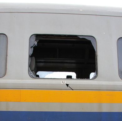
At each end of the coach, there are side-facing end doors and retractable steps used for boarding at station platforms. In emergency situations, the doors can be opened from the outside by emergency responders. The instructions for opening the doors from the exterior are contained on a small inconspicuous pictogram located just to the right of the bottom of the door.
1.28.6 VIA light, rapid, comfortable coach passenger restraint
There were no indications that any of the coach seats had separated during the accident. The design standards do not require passenger seats to be equipped with seat belts, and none were provided. A number of occupants sustained injuries as they fell from their seats during the accident.
A wheelchair station installed at the rear of the first coach was occupied during the journey. The available tie-down restrained the wheelchair, but its occupant was not fastened to the wheelchair. During the accident, the wheelchair passenger fell to the opposite side of the cabin when the coach rolled onto its side.
1.29 Locomotive video recorders
There is no regulatory requirement to equip locomotives with forward-facing video recorders. However, at the time of the accident, 41 of VIA's GM F40PH-2D locomotives had been rebuilt and returned to service. Of these 41 locomotives, 32 were equipped with forward-facing video recorders while the 9 other rebuilt locomotives, which included the occurrence locomotive VIA 6444, were returned to service without forward-facing video recorders. Following the accident, VIA equipped the remaining GM F40PH-2D locomotive fleet with forward-facing colour video recorders.
A summary of locomotives operated by VIA, CN and CPR that are equipped with colour video recorders as of February 2013 is contained in Table 5
| Railway | Number of road locomotives | Number equipped with forward-facing video cameras | Number equipped with in-cab video cameras |
|---|---|---|---|
| VIA | 74 | 53 | 0 |
| CN | 1347 (North America) | 739 | 0 |
| CPR | 1539 (North America) | 714 | 0 |
1.30 Crew medical and toxicology information
The VIA 92 LE and trainee were both fit for duty.
The ICLE had been suffering from a mood disorder and had had difficulties managing the use of alcohol for over 10 years. The ICLE family doctor had been monitoring these conditions and the ICLE had also been provided with treatment for the mood disorder in the form of the psychiatric medications (that is, bupropion and quetiapine) over a long period. Toxicology results for the ICLE showed the presence of these drugs and oxycodone in the blood as well as the presence of alcohol in the urine. Quetiapine may cause drowsiness as does the opiate oxycodone. The presence of alcohol in the urine without any being detected in the blood indicates that the alcohol was likely consumed over 12 hours prior to the time that the ICLE sustained the fatal injury. Both alcohol and opiates are known to fragment sleep, decrease rapid eye movement (REM) and disrupt the normal sleep cycle. Footnote 20
While the family doctor monitored symptoms of the mood disorder, there was no recent request for a psychiatric report that would have provided a more definitive diagnosis. Therefore, the exact nature of the mood disorder and/or potential substance-related disorder could not be determined. Individuals working in safety-critical positions, such as an operating crew member, who have these health conditions must be carefully assessed and regularly monitored if they continue to work. The drugs used to treat these conditions, such as quetiapine, may lead an individual to be excluded from a safety-critical position. Footnote 21
After taking reasonable steps to first inform the employee, under the Railway Safety Act, physicians are required to report to railway companies when, in their opinion, an individual in a safety-critical position has a medical condition that is likely to pose a threat to safe railway operations. For guidance, the Railway Association of Canada (RAC) has issued an information leaflet Footnote 22 for medical practitioners outlining their responsibilities for reporting. In this case, neither condition was reported to VIA by the family doctor as the doctor viewed the conditions to be stable. The family doctor did not recognize that the assessment required the identification of both the current conditions and the historical conditions.
Employees also share in reporting responsibilities. Prior to any medical examination, employees must advise their physicians if they hold a safety-critical position in a railway company. Employee responsibilities also include being fit for duty, undergoing proper diagnostic testing and treatment programs, and properly reporting medical conditions to their physicians and companies. Several TSB reports Footnote 23 have identified cases where individuals in safety-critical positions have not reported significant information to their employer or provided it during a periodic medical assessment.
In the aviation and marine modes, periodic medical assessments are carried out by TC–approved physicians with a background in occupational medicine. These physicians also undergo training in assessing occupational safety issues related to the candidate's medical health. The results of the assessments are sent to TC for review. In comparison, in the rail mode, the assessments are carried out by physicians whose role is to document the medical conditions and then to send the form to the company for assessment. The physician who conducted the ICLE's assessment did not have a qualification in occupational health medicine. Although required to, neither the ICLE nor the physician declared the medical conditions to VIA following the periodic medical assessment.
In order to improve the management of medical issues related to safety, following the derailment in 2011 of VIA train No. 15 at Saint-Charles-de-Bellechasse, Quebec, and publication of TSB report R10Q0011, Footnote 24 VIA and CN placed increased attention on ensuring that medical files were transferred between companies when an employee changed employer. VIA subsequently changed its practice of relying on the previous employer's medical assessment until the next periodical medical examination and now requires new operating employees to pass a VIA pre-employment medical assessment.
However, in this occurrence, when the ICLE transferred to VIA in 2009, no such practice was in place. As a consequence, VIA medical staff were unaware of the issues documented in CN's medical files for the ICLE and had not been informed by the physician or the ICLE of the medical issues. Furthermore, the VIA company physician did not request the ICLE historical medical file for review.
1.31 Regulatory requirements regarding passenger handling
Railway passenger safety is governed by the TC–approved Railway Passenger Handling Safety Rules (Passenger Handling Safety Rules) dated 31 March 2000 (TC O-0-16). Section 4, Passenger Handling Safety Plans, of these rules states in part
Each railway company that operates or hosts passenger/mixed train service shall have a written passenger handling safety plan which, as a minimum, encompasses all of the following measures applicable to the type of equipment and operation:
- medical;
- on-board fire;
- derailment or collision;
- passenger evacuation procedures;
- incident recording and reporting;
- passenger safety awareness procedures;
- training;
- communications;
- safety checks;
[...]
Each railway passenger handling safety plan shall incorporate directly or by reference, the railway's emergency response procedures including periodic exercises.
Section 5, Training, of the Passenger Handling Safety Rules states in part
Each railway company that operates or hosts passenger train service shall ensure a sufficient number of on-board personnel as defined in the company's safety plan […] are as a minimum, trained:
- with the passenger handling safety plan;
- with the company's emergency response procedures;
- with the safety features of passenger equipment;
- with normal and emergency communication procedures;
- with the use of on-board emergency tools;
- to administer first-aid and CPR;
- to provide service to passengers with disabilities under normal and emergency situations;
- to supervise or assist in emergency evacuation procedures.
Section 6, Passenger Safety Inspections, of these rules states in part
In the Passenger Handling Safety Rules, there is no minimum ratio of on-board service personnel to passengers.
In comparison, within the aviation industry, passenger safety is governed by the Canadian Aviation Regulations. Part VII, Commercial Air Services, Subpart 5, Airline Operations, Division VII, Personnel Requirements, item 705.104 (1), Flight Attendant Requirements, of these regulations states in part:
- [...] no air operator shall operate an aircraft with passengers on board unless the crew includes at least the following number of flight attendants:
- 1 to 40 passengers on board, one attendant;
- 41 to 80 passengers on board, two attendants; and
- 81 or more passengers on board, one attendant for each unit of 40 passengers or portion thereof.
1.32 VIA ticketing and passenger manifest
Each VIA passenger requires a ticket to be on the train. At major terminals, passengers get their tickets at the check-in counter and the ticket is logged on the passenger manifest. At smaller terminals, passengers are able to board the train without a ticket. In these cases, the passenger would purchase a ticket on board from VIA personnel. Once the train departs the station, VIA on-board service personnel take a ticket stub from each passenger and all stubs are stored in a fire-resistant pouch. The stubs are later manually reconciled with the passenger manifest to determine who is on board. At the time of the accident, there was no system in place to monitor VIA passenger manifests in real time.
1.33 VIA passenger handling safety plan
In accordance with TC–approved Passenger Handling Safety Rules, VIA has a Passenger Handling Safety Plan that incorporates VIA's emergency response procedures. The plan was originally drafted in 2000 and the most recent version was revised in October 2010 and filed with TC in July 2011. The plan indicates that
- The ICLE is responsible for the overall response to any emergency, including evacuation.
- The SM, under the direction of the ICLE, is in charge of the on-board service personnel.
- The SM and ICLE shall ensure that prior to departure from the train's initial station, a pre-departure briefing is conducted. Amongst other things, pre-departure briefings should address any pre-identified passenger and station where special handling will be required and the assignment of emergency responsibilities.
- The plan contains contingencies for medical emergencies, on-board fire and evacuation.
- While the plan's emergency procedures assign specific tasks to designated employees, it also identifies that, due to injury or extenuating circumstances, it may be necessary for other employees to assume those roles, which includes coordinating an evacuation.
The plan does not contain specific measures for responding to a catastrophic accident involving derailment and/or collision. There is no minimum ratio of on-board service personnel to passengers defined in the plan.
1.34 Passenger restraint study
In 2007, the Rail Safety and Standards Board (RSSB) of the United Kingdom published a study on passenger containment. Footnote 25 The study, which compiled crashworthiness research of rail vehicles, was conducted on behalf of the rail industry with the objective of improving rail accident prevention and the protection of passengers. The research was initiated
- to identify the causes of injuries to passengers,
- to understand the way in which those injuries were sustained, and
- to identify possible ways to reduce or eliminate such injuries.
Given that operating crews face similar risks in the event of a collision or derailment, many of the findings from the RSSB study can be applied to crew restraint.
Accident data analysis indicated that the overall level of injuries had declined and the type of injuries had changed, primarily due to improved rail vehicle design. However, involuntary exit as a result of crew or passengers being ejected through windows during jackknife derailments or rollover derailments was becoming a more significant cause of injury. In the aftermath of several major accidents in the United Kingdom, there were calls for rail passenger vehicles to be fitted with seat belts.
The study evaluated 2-point and 3-point seat belts using crash test dummies that were representative of small-, medium- and large-sized people. A variety of seat intervals that were representative of those in current rail vehicles were evaluated. It was determined that
- The use of 2-point seat belts was likely to increase the severity of injuries to unacceptable levels, particularly to the neck area.
- The injury levels experienced by unrestrained passengers occupying seats designed to the latest crashworthy standards were well within acceptable limits.
- Using 3-point seat belts, injury levels were reduced below those for unrestrained passengers occupying crashworthy seats, although both were within acceptable limits. However, in order to support the increased loads imposed by the use of 3-point seat belts, the seats had to be strengthened, which negated their crashworthiness and increased neck injuries to unrestrained passengers.
- Seat belts are predominantly designed to protect people in the event of longitudinal impact and, in the case of aircraft, vertical movement. With regards to rail rolling stock, in the event of vehicle jackknife and/or rollover derailment, which includes a lateral force component, the effectiveness of seat belts could not be consistently relied upon.
- In cases where survival volume had been severely reduced or lost due to collapse or crush of the rail vehicle structure, some passengers had been thrown clear of an area struck during the accident.
- For every life that may have been saved by the use of seat belts, potentially 8 lives may have been lost by being restrained in areas where the loss of survival volume occurred.
Presently, in Europe and North America, there is no requirement for the installation of seat belts for crew or passengers on any rail rolling stock, including high-speed trains.
1.35 VIA overspeed incidents and accidents (2005 to 2012)
A summary of VIA passenger train incidents and accidents from 2005 to 2012, involving excess speed, is summarized in Table 6.
| TSB occurrence number | Occurrence date | Occurrence description | Authorized track speed (mph) | Approx. train speed (mph) |
|---|---|---|---|---|
| R05T0053 | 04-03-2005 | Train 87 excess speed derailed locomotive and all 5 coaches (no passengers) on crossover at Burlington, Ontario (Mile 30.50). | 15.0 | 65.0 |
| R07H0209 | 24-10-2007 | Train 30 excess speed entering siding at Glen Robertson, Ontario | 30.0 | 59.0 |
| R08T0118 | 24-04-2008 | Train 60 excess speed through crossover at Pickering, Ontario | 45.0 | 70.8 |
| R08T0356 | 11-06-2008 | Train 48 excess speed through crossover at Moira, Ontario | 45.0 | 70.0 |
| R08T0357 | 19-06-2008 | Train 73 excess speed through crossover at Bayview, Ontario | 15.0 | 28.0 |
| R09T0242 | 03-09-2009 | Train 60 excess speed through crossover at Mallorytown, Ontario | 45.0 | 65.0 |
| R10Q0011 | 25-02-2010 | Train 15 excess speed derailed 2 locomotives and 6 coaches on siding turnout at Saint-Charles-de-Bellechasse, Quebec | 15.0 | 64.0 |
| R11T0303 | 30-10-2011 | Train 61 excess speed through crossover at Danforth, Ontario | 45.0 | 73.0 |
| R11D0107 | 23-11-2011 | Train 22 excess speed through siding switch at Saint-Cyrille, Quebec | 15.0 | 42.0 |
| R12T0202 | 04-02-2012 | Train 62 excess speed through crossover at Mile 209 of the Kingston Subdivision at Marysville, Ontario | 45.0 | 62.0 |
1.36 TSB Watchlist
The TSB Watchlist serves as a blueprint for change in transportation by generating discussion and engagement by key stakeholders. The Watchlist identifies the transportation safety issues that pose the greatest risk to Canadians. Based on investigation reports, safety concerns and Board recommendations, the first Watchlist was released in 2010 and then revised in June 2012. The 2012 Watchlist includes the following 2 rail safety issues:
- Following signal indications, and
- Voice and video recorders.
1.36.1 Following signal indications
Since 2002, there has been an average of 11 Footnote 26occurrences per year where a signal indication was misidentified, misinterpreted or not immediately recognized. This type of occurrence can result in a train collision or derailment, and consequently, there can be significant risk to the public and the environment.
Since 1911, the railway industry in Canada has relied on Centralized Traffic Control System (CTC), a system of visual signals, to control traffic on a significant portion of its network—currently more than 44 000 km of track. Footnote 27 The CTC provides train crews with a series of signal indications requiring actions relative to the signal displayed. If signal indications are not followed, the CTC cannot ensure that trains on the same line are separated appropriately. The CTC does not provide any warning that a train may be passing beyond a restricted location, nor does it provide automatic means to slow or stop a train before it passes a stop signal or other points of restriction.
To augment CTC safety measures, railways have adopted various other defence mechanisms to help prevent accidents, such as 2-person crews, CROR, and GOI. However, these defences have proven inadequate in situations where the train crew misinterprets a signal indication and/or does not apply, or misapplies, an operating rule.
1.36.2 Voice and video recorders
Objective data are invaluable to investigators in helping them understand the sequence of events leading up to an accident and identifying operational issues involving human factors and crew performance. Voice recordings would allow TSB investigators to confirm crew communications as well as crew actions and interactions. Such information would also allow accident investigators to more quickly eliminate extraneous factors that did not play a role in the accident. Technology for recorded information is abundant and has been for some time. The aviation industry has had cockpit voice recordings for over 30 years.
A number of rail accident investigations in North America have led to findings, recommendations and other safety communications where human factors were identified as an underlying condition. Many of these investigations would have benefitted from a recording of crew communications immediately prior to the accident.
TC's Safety Management System Regulations mandate that, as of 31 March 2001, all railway companies operating on federally regulated railways must implement and maintain a safety management system (SMS). The regulations are accompanied by an implementation guide to assist railways in developing their SMS and in meeting the minimum requirements of the regulations. The guide also suggests ways of incorporating other safety-related systems and processes under the SMS umbrella to ensure a comprehensive management approach to safety.
The Safety Management System Regulations require railways to establish a formal framework for integrating safety into day-to-day operations. This includes safety goals and performance targets, risk assessments, responsibilities, authorities, rules, procedures, monitoring and evaluation processes for all aspects of operations. As part of monitoring and evaluating operating processes, railways currently make use of recorded information such as data from the locomotive event recorder. While some railways are considering installing in-cab voice and video recorders for day-to-day use in their SMS, Canadian law, under the Canadian Transportation Accident Investigation and Safety Board (CTAISB) Act, protects these recordings and does not currently allow for their use, except as part of a TSB investigation.
The following TSB Laboratory report was completed:
- LP 039/2012 – Crashworthiness Examination of Passenger Train VIA 92
This report is available from the Transportation Safety Board of Canada upon request.
2.0 Analysis
The CROR specify that the responsibility for rules compliance, including signal recognition and confirmation, is equally shared among all crew members present in the cab. If a signal recognition error is made, it is made by the crew and cannot be attributed solely to one crew member.
In this occurrence, no equipment or track defects were considered causal. The VIA 92 LE and ICLE were familiar with the territory, while the entire operating crew met rest requirements and were qualified for their respective positions. There was no evidence that the crew had been using electronic devices that could have impeded their performance.
The analysis will focus on railway signals, operation of the train, human performance and situational awareness, safety defences in CTC territory, alternate forms of train control, rolling stock crashworthiness, railway medical assessments of locomotive engineers, passenger evacuation and emergency response, and passenger handling and the use of seat belts.
2.1 Verification of signal system
The progression of signals encountered by VIA 92 upon its approach to the accident location at Aldershot East (Mile 33.30) was critical to the investigation yet could not be immediately determined. The absence of forward-facing video and in-cab voice and video recorders presented difficulties for the investigative team in determining the signal aspects displayed and the crew's perceptions and reactions. Consequently, extensive testing of the CN signal system was necessary. The independent testing concluded that, immediately before the accident, with the No. 5 crossover at Mile 33.23 lined to bring VIA 92 from track 2 to track 3, the signal system functioned as designed and displayed the following progression of wayside signals:
- Controlled signal 364T2 - Clear to Limited signal (Rule 406) with aspects Y/FG/R.
- Advance signal 348T2 - Clear to Slow signal (Rule 409) with aspects Y/Y.
- Controlled signal 334T2 - Slow to Limited signal (Rule 432) with aspects R/FY/FG.
2.2 The accident
On its approach to Aldershot Station (Mile 34.60), VIA 92 first encountered controlled signal 364T2 at Snake, which displayed a Clear to Limited signal. This meant that VIA 92 could proceed at track speed and approach the next signal at a limited speed not exceeding 45 mph. The next signal that VIA 92 encountered was advance signal 348T2 at Waterdown, which displayed a Clear to Slow signal. This meant that VIA 92 could proceed at track speed and approach signal 334T2 (Aldershot East) at a slow speed not exceeding 15 mph. However, before VIA 92 encountered signal 334T2, it made its regular stop at Aldershot Station.
Normally, after the stop at Aldershot Station, VIA 92 would be routed straight through on track 2. However, on this occasion, in accordance with standard railway operating practices but unknown to the operating crew, the RTC planned to route VIA 92 around the signal maintainer's TOP on track 2. The track switches were lined to route VIA 92 from track 2 to track 3 through crossover No. 5 at Mile 33.23, which had an authorized speed of 15 mph.
At 1523:26, VIA 92 departed Aldershot Station on track 2. The locomotive throttle was increased slowly up to notch 8. At 1525:33, while travelling at about 65 mph, VIA 92 passed controlled signal 334T2, which displayed a Slow to Limited signal. This meant that VIA 92 was required to proceed at slow speed, not exceeding 15 mph, past the signal, through crossover No. 5 and approach the next signal at a limited speed not exceeding 45 mph. However, VIA 92 continued to accelerate as it approached crossover No. 5.
lthough the area was designated as anti-whistling, at 1525:26, the VIA 92 crew began sounding the train horn repeatedly. At 1525:39, the locomotive throttle was reduced to notch 6 and 1 second later, to notch 3. At 1525:44, the throttle was moved to idle just after VIA 92 had entered crossover No. 5 while travelling at 67 mph. The locomotive entered the crossover at excessive speed and was moving diagonally when it derailed, flipped to its side, slid down the embankment and collided with the building abutment all within approximately 2 seconds. There was no time for any of the crew to take cover. The inertia from the rapid rollover threw the crew members to the locomotive engineer's side of the cab into an area that was compromised by the collapse of a locomotive cab roof structure built with relatively light gauge material. Subsequently, all 5 coaches also derailed. During the accident, there was no train- or operator-initiated emergency brake application.
In response to the signal indication displayed at signal 334T2, VIA 92's speed should have been reduced to 15 mph. The absence of any attempt to slow the train indicates that the VIA 92 crew members expected to proceed at track speed. Given these circumstances, it is likely that they either misinterpreted the signal 334T2 indication as Clear (Rule 405) with aspects G/R/R or as Advance Clear to Limited (Rule 412) with aspects FY/FG/R. In either case, the operation of the train and its speed of 67 mph at the crossover were consistent with the actions of a crew that had misperceived or misinterpreted signal 334T2's indication, which restricted VIA 92 to 15 mph through the crossover, as being more permissive allowing them to proceed at track speed.
The investigation considered that the crew might not have observed signal 334T2 but discounted this possibility for the following reasons. There were 3 people in the cab, each of whom would have had to miss the signal completely. The VIA crew members were well rested, familiar with the territory and had only worked just over 2 hours on this trip. When stopped at Aldershot Station, the signal structure was directly in front, with no obstructions. After departing Aldershot Station, approaching signal 334T2, the signal indications were in clear view for at least 2 minutes and the saliency of the flashing lights would have been difficult to miss or ignore. Finally, because of the interruption immediately prior to the accident—the stop at the station—there was not sufficient time for the crew to fall asleep; therefore, it is unlikely that vigilance was significantly reduced immediately before the accident. Consequently, it is much more likely that the signal was observed but misinterpreted.
2.3 Factors contributing to signal misinterpretation
Considering that the operating crew was very experienced, the question becomes how such a crew could have misperceived or misinterpreted a visible signal indication. Without any in-cab voice recordings, it is impossible to identify the precise cause with certainty. However, there were a number of factors which, in isolation or combination, may have reinforced the misinterpretation by the operating crew that signal 334T2 displayed a more permissive indication.
2.3.1 Stop at Aldershot Station
During VIA 92's approach to Aldershot Station, it encountered signal 364T2, which displayed a Clear to Limited signal (Y/FG/R) and signal 348T2, which displayed a Clear to Slow signal (Y/Y). This series of signals indicated to the crew to proceed and approach signal 334T2, which was located about 1 mile east of Aldershot Station, at 15 mph. The indications displayed were each part of a progression of signals indications that governed VIA 92's movement. The stop at Aldershot Station was a separate event that interrupted the progression.
While approaching the station, the crew's primary focus would have been to bring the train to a stop at the station and not on the next signal (334T2). The stop of several minutes in Aldershot created a condition that was favourable to forgetting what the previous signal had displayed. At the time of the occurrence, there was nothing in place at the station or in the cab to remind the crew of the indication displayed at the previous signal (348T2), nor was there an administrative procedure for the crew to re-confirm the previous signal indication before departure. The stop at Aldershot Station interrupted the continuous progression of signals, which may have contributed to the locomotive crew members forgetting that the previous advance signal 348T2 displayed a Clear to Slow (Y/Y) indication and what was expected with respect to operating speed once they recommenced the trip. When the continuous progression of signals is interrupted (for example, by a stop), the absence of a repeater signal or procedure to re-confirm the previous signal indication increases the risk of a crew misinterpreting the following signal.
2.3.2 Infrequent use of No. 5 crossover at Mile 33.23
In this area, eastbound VIA trains regularly travel on track 2. Almost all of the time, the VIA trains are presented with a Clear signal (G/R/R) at signal 334T2, which permits the crew to accelerate the train towards track speed and remain on track 2 beyond the signal and past the crossover. Such a situation is known to be conducive to habituation, or conditioning over time. In such cases, operating crews who continually work the same route can develop a bias towards an expectation that the train will follow the usual route. The frequent use of track 2 may have influenced the misperception of signal 334T2 as being more permissive, which led to inappropriate train control for the restrictive signal indication displayed.
2.3.3 Misinterpreting signal 334T2 as advance clear to limited (Rule 412)
At the time of the accident, signal 334T2 displayed a Slow to Limited signal (Rule 432) with aspects R/FY/FG. While the sunlight shone towards signal 334T2, the long light hoods prevented light from falling directly on the aspects thus preventing flooding of the indication. While the signal indication was likely visible from the east end of Aldershot Station, it may not have been readily identifiable from over a mile away. Due to the daytime ambient light and at that distance, the top solid red aspect would have been less conspicuous than the FY/FG aspects. While the solid red light on top of the signal should have meant a speed restriction to the crew, the saliency of the flashing lights would have been more prominent and would have
captured one's attention. As VIA 92 approached signal 334T2, this may have led to the grouping of the FY/FG aspects and the exclusion of the grouping containing the single top red aspect of signal 334T2 with the adjacent red indications at signal 334T1 and signal 334T3. Footnote 28
The signal indication for Slow to Limited signal (Rule 432) with aspects R/FY/FG restricts train speed to 15 mph at the signal. Another signal indication that includes the FY /FG combination is Advance Clear to Limited signal (Rule 412) with aspects FY/FG/R. Rule 412 permits the train to proceed past the signal at track speed.
The nuance between Rule 412 and Rule 432 is the location of the red light. This small but critical difference can be overcome with progression of signals. However, once the progression is interrupted, as was the case with VIA 92's stop at Aldershot Station, the discontinuity in the progression may not have been apparent. Consequently, the VIA 92 crew members may have become focussed on the more salient FY/FG aspects and misinterpreted that signal 334T2 displayed Advance Clear to Limited (Rule 412), which allowed them to proceed at track speed rather than Slow to Limited (Rule 432), which should have restricted VIA 92 to 15 mph.
2.3.4 Routing of VIA 92 east of Aldershot station
Although the RTC's planned route for VIA 92 around the signals work crew TOP east of Aldershot Station was unusual, the RTC did not contact the VIA 92 crew to inform them of the TOP ahead on track 2, nor was the RTC required to. In the railway industry, RTCs minimize the amount of information passed on to locomotive crews in order to reduce the risk of anticipation that could generate crew expectation and result in bias with regards to the perception Footnote 29of signals ahead of the train.
The principle of progression for a series of signals is strongly instilled in experienced train crews. They are trained and expected to react to wayside signal indications as presented along the route and this is a reasonable expectation in most situations. However, in some situations, additional information could assist and reinforce decision making, particularly in situations that differ from those routinely experienced by the crew. For example, had the VIA 92 crew members been informed of the TOP ahead on track 2, they may have questioned their perception that signal 334T2 was permissive. On the other hand, additional information could also result in crew expectations that can have a negative impact on decision making, which has been identified in other TSB investigations such as R10Q0011.
Prior to departing Niagara Falls, the VIA 92 operating crew was informed that a wheelchair passenger would be disembarking in Oakville. Due to their experience on the Oakville Subdivision, the VIA 92 crew members would have known that, for convenience, wheelchair passengers usually disembark on the platform adjacent to track 1 at Oakville Station. Since VIA 92 was usually routed straight through on track 2, this information likely created a crew expectation that they would cross over to track 1 before Oakville. Considering that VIA trains are usually routed through the 45 mph crossovers near Burlington, crossing from track 2 to track 3 using a 15 mph crossover in order to get to track 1, while in accordance with operating practice, would have been an unusual routing that is rarely used (see Figure 6).
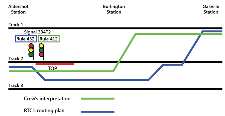
The crew's advance knowledge of an upcoming wheelchair passenger disembarkment at Oakville may have created an expectation that they would remain on track 2 and cross over from track 2 to track 1 near Oakville, which reinforced the perception bias towards a permissive signal indication.
2.3.5 Presence of the signals work crew
The work crew was not visible from Aldershot Station. Approximately 20 seconds before the derailment, when VIA 92 was about 1000 feet ahead of signal 334T2, the crew activated the train horn in a zone that was designated as anti-whistling (horn). This suggests that the crew noticed the signals work crew on the track approximately 2500 feet away near the HBD on track 2.
The presence of the signals work crew on track 2 should have been a cue for the crew members to question their interpretation of signal 334T2. However, once the crew members had misinterpreted the signal 334T2 indication as permissive, it would have been difficult to change their mental model.
The throttle manipulation, lack of an operator-initiated brake application and the repeated activation of the train horn in an anti-whistling (horn) zone are indicative of a crew having expectations that they would continue to proceed on track 2. The activation of the train horn in particular indicates that the crew became focussed on the safety of the signals work crew, convinced that the work crew should not have been on track 2.
In addition, the signals work crew vehicle, which could be seen from the locomotive cab, was located north of and adjacent to track 1, rather than occupying track 2, which often happens when track work is performed under the protection of a TOP. The vehicle location would have also been consistent with track workers working under a Safety Watch, which was no longer permitted in this area. However, VIA operating crews would not have been aware that CN had cancelled Safety Watch as a method of track protection on all Class 5 double main-track territory in December 2011. Given these circumstances, and unaware of the TOP protecting track 2, it was likely that the VIA 92 crew believed that the signals work crew were either working under a Safety Watch or had strayed away from an adjacent track and should not have been on the track.
To maintain situational awareness, it is often necessary to switch attention between different information sources. When confronted with these types of situations, people can often get trapped in a phenomenon called attention narrowing or tunnelling. When succumbing to tunnelling, one tends to lock in on certain aspects or features of the environment they are trying to process and may either intentionally or inadvertently lose their primary focus. In this case, the crew's situational awareness was likely focussed on resolving the apparent track occupancy conflict of the signals work crew working ahead on track 2 rather than properly identifying the signal 334T2 indication and complying with the requirement to slow their train.
2.3.6 Additional crew member in locomotive cab
Operating with a 3rd crew member has been a long-standing industry practice and has proven to be an effective training tool, particularly with regards to familiarization, qualification of operating crews and proficiency testing. In these situations, the responsibility of rules compliance is equally shared among all crew members in the cab.
When operating in CTC territory, crew members within physical hearing range must communicate to each other, in a clear and audible manner, the signal indication by name. If prompt action is not taken to comply with the requirements of each signal indication affecting their movement, crew members must remind one another of such requirements. If no action is then taken, other crew members must take immediate action to ensure the safety of the movement, including stopping it in emergency if required. This administrative defence is in place to mitigate the risk of having an operating crew miss a signal or misinterpret a signal indication.
While there may be an expectation that the presence of a 3rd crew member in the cab could reduce the risk, this may not necessarily be the case. If the 3rd crew member is seated in the middle jump seat, the forward vision (that is, view of the signals ahead) of the additional crew member can be impeded by the post between the 2 forward-facing locomotive windows. Furthermore, with a 3rd crew member, there may be a propensity for more conversation, which can lead to distraction, and there can be a tendency to rely on the other crew members to comply with the rules. In addition, at the time of the accident, VIA did not provide training on how to mitigate the risks associated with a 3rd person in the locomotive cab. In the absence of training and procedures governing situations when there are 3 operating crew members in the locomotive cab, there is an increased risk of distraction.
2.4 Following signal indications
There are a number of safety defences in place throughout the Québec–Windsor corridor that are designed to prevent accidents of this type. Some of these defences are associated with the CTC train control system and some are associated with administrative protocols and rules such as the CROR and the railway's GOI.
Wayside signals provide a physical signal installation combined with an administrative requirement to follow the signal indication. This defence relies on the train crew to observe the signal, recognize the intent of the signal, and take appropriate action. Operating rules and company GOI require that all signals be identified and announced within the cab and that some signals be announced over the railway radio system. These defences, while of value, are inadequate in situations where the train crew misperceives, misinterprets or does not follow a signal indication.
While reliance on strict rule compliance has been a cornerstone of railway safety philosophy in Canada for over 100 years, it is not fail safe and has limitations. This accident is one in which the requirement to follow rules failed to compensate for human error. Human error must be anticipated as even the best trained and well-meaning employees will occasionally make errors. By not anticipating and planning for error in the design of a safety-critical system such as railway operations in signalled territory, the system is predisposed to failure.
For more than a decade, the Board has had an outstanding recommendation calling for additional defences in signalled territory to help ensure that signal indications are consistently recognized and followed. In this occurrence, the signal indications were appropriate but were not correctly identified or followed and the subsequent train-control decisions that led to the accident were not appropriate. This has also been true in other accidents investigated by the TSB and demonstrates that, in the absence of additional physical fail-safe train control defences in signalled territory, when signal indications are not correctly identified or followed, existing defences have proven to be inadequate to reduce the risk of collision and derailment.
2.5 Additional train control defences for the centralized traffic control system
In CTC territory, the administrative defences contained in the CROR and railway GOI require operating crews to take action relative to the wayside signal indications displayed. However, the CTC does not ensure positive train separation. It does not provide any indication that a train may be about to pass beyond a restricted location, nor does it provide automatic enforcement to slow or stop a train before it passes a stop signal or other point of restriction. The CTC does not display the train's exact location within a block, nor its speed.
Since 2005 and prior to this occurrence, VIA has reported 10 occasions where a VIA train entered a crossover or siding switch at excessive speed. On 2 of the 10 occasions, the VIA train was travelling at 4 times the speed authorized for the crossover or switch and each of these cases resulted in derailment.
The TSB has conducted 5 investigations (involving both passenger and freight railway companies) where the misperception and/or misinterpretation of wayside signal indications by operating crews has been a cause or contributing factor. While overspeed occurrences can result from operating crew members forgetting/not recognizing that they are in an area protected by a slow order, overspeed can also be caused by misinterpreting a signal indication restricting train speed.
The concept of “defence in depth” is one that has been known to some industries for many years. Layers of defences or redundancy have proven to be a successful approach to ensure a single system failure does not lead to catastrophic consequences. The issue of following signal indications is a good example of a situation where inadequate defences can permit a single-point failure Footnote 30 during which an inappropriate response to a signal indication can result in a serious accident. This accident involved a passenger train with an impending danger to the crew, passengers, businesses and residents in the vicinity of the track. Any one of a number of train control defences such as cab signalling, ATC, ACSES, I-ETMS or other form of PTC may have prevented this accident. While the need for additional physical fail-safe safety defences to reduce the consequences of inevitable human errors in signalled territory has been on the safety radar for years, the Canadian railway industry and regulator have not yet taken the necessary steps to reduce the risk.
2.6 Operations re-enactment using Amtrak train simulator
VIA 92 approached controlled signal 334T2 in a manner indicative of the crew expecting to proceed at track speed rather than having to reduce speed as required. While railways have defence mechanisms in place to prevent this situation or to mitigate the consequences, these mechanisms do not consistently provide a reliable safety barrier.
By comparison, other defences have the ability to alert crew members if they do not respond appropriately to a signal or other restriction, some of which can intervene to slow the train or stop the train by applying the brakes. The TSB has discussed the benefits of these other defences in a number of investigation reports and found that such systems have the potential to significantly reduce the risk of overspeed, train collision and/or signal misinterpretation.
Technology to reduce the risk and prevent these types of accidents has been developed and in use in the United States for over 60 years. For example, since 1938, passenger locomotives that operate on the NEC have been equipped with cab signals that display wayside signals in the locomotive cab to the operator. Since 1947, for any railway line in the United States on which train speed exceeds 79 mph, the railway operator is required to be equipped with in-cab signals, automatic train stop or ATC.
Since 1952, passenger locomotives that operate on the NEC have also been equipped with a fully functioning ATC system that incorporates cab signals and speed control with a penalty brake. If a train operator does not respond to the signal displayed in the cab, the system automatically applies a penalty brake application to control the train speed in accordance with the signal indication displayed. Since 2000, Amtrak ATC has been supplemented by the ACSES, which provides enhanced train control for high-speed trains travelling at speeds up to 150 mph.
As part of an operations re-enactment, an Amtrak train simulator equipped with cab signalling and ATC was programmed with a progression of signals similar to those displayed for VIA 92. The simulation determined that, after stopping at Aldershot Station, VIA 92 would have been limited to 20 to 30 mph upon departure up to signal 334T2 just before crossover No.5. If the crew did not take further action to reduce speed approaching the signal, after the train passed signal 334T2, the ATC would enforce a further speed reduction. This demonstrated that, when locomotives are equipped with cab signals and ATC, the risks associated with signal misinterpretation and overspeed are greatly reduced.
2.7 Rolling stock crashworthiness
Structural deformation of rolling stock can be beneficial during a collision as energy is absorbed and dissipated that would otherwise be transmitted directly to the occupants. The basic principle of crash energy management (CEM) is to ensure that, during a collision, the unoccupied spaces deform before the occupied spaces. Survivability is influenced by how well the impact is absorbed by features of the vehicle and directed away from the occupants. Any structural damage of the container should not reduce the size of the survivable volume or open it up to the elements to the point where it compromises occupant survivability.
2.7.1 Locomotive crashworthiness
The front nose section of GM F40PH-2D locomotives contain 2 collision posts to protect against frontal collision. However, the roof structure and cab sides were constructed with various configurations of light gauge steel. There was no significant corner post structure and no rollover protection. During VIA's locomotive rebuild program, there was no structural upgrade in the area of the cab to protect against rollover or impact, nor was it required.
The TC–approved Locomotive Safety Rules require that new freight locomotives be designed and constructed in accordance with the latest revision of the AAR Locomotive Crashworthiness Requirements S-580 or equivalent standard. New passenger locomotives are required to be designed and constructed in accordance with either the latest revision of AAR S-580, the APTA standard or an equivalent standard. AAR S-580 does not require cab corner posts extending above the short hood structure nor cab rollover protection for new wide-nose locomotives nor is cab rollover protection required for narrow-nose locomotives in either freight or passenger service. In comparison, the APTA standard requires both cab corner posts and rollover protection for passenger locomotives and has engineering performance criteria for both. The lack of AAR design criteria for cab corner posts for newly constructed wide-nose locomotives and design criteria for rollover protection for both wide-nose and narrow-nose locomotives increases the risk that new locomotives may be susceptible to cab structural failure during rollover derailments leading to loss of survivable volume.
In this occurrence, after derailing, locomotive VIA 6444 rolled over and struck the concrete foundation of a building. The front and nose area was substantially undamaged while the cab roof area was crushed downwards, which reduced the survivable volume. Due to the nature of the accident, it could not be determined with any certainty if the crew would have survived even with improved rollover protection. While it is recognized that it may not be possible to design a vehicle in which the occupants survive all crash scenarios, survivability will improve with more robust design.
For locomotives built after 01 July 1995, AAR S-5506 requires improved structural and puncture resistance properties of locomotive fuel tanks to reduce the risk of fuel spillage resulting from derailment and/or collision. Since VIA 6444 was constructed prior to 1995, the installation of a puncture-resistant fuel tank was not required. During the accident, the fuel tank was punctured and released approximately 4300 litres of diesel fuel. The tank was damaged in an area that AAR S-5506 requires to be more robust and high impact resistant. While there was an opportunity to upgrade the fuel tank during the VIA rebuild program, with no regulatory requirement to replace it, the original tank was re-installed and subsequently failed during the accident.
AAR S-580 requires that a truck attachment that secures each truck to the frame of the locomotive must be able to withstand an equivalent ultimate shear value of 250 000 pounds from the longitudinal to lateral, inclusive. In this accident, both trucks separated from the locomotive. In particular, the rear truck separated, derailed and came to rest approximately 1000 feet east of the locomotive, near the signal maintainers. The truck securement failure suggests that the original design was inadequate for the accident conditions. While there was an opportunity to upgrade the securement during the VIA rebuild program, without a regulatory requirement, the original truck securement remained and subsequently failed during the accident.
The GM F40PH-2D locomotives were built prior to the establishment of crashworthiness standards and, once rebuilt, the service life of these locomotives can extend up to 40 years or longer if rebuilt again in the future. However, given that the Locomotive Safety Rules and the associated standards only apply to new locomotives, there is no regulatory requirement to upgrade the cab structure, fuel tanks or truck securement of rebuilt locomotives. Furthermore, over 90 % of road locomotives operated by major Canadian railways were built prior to the establishment of current crashworthiness standards, and under the current Locomotive Safety Rules, none of these locomotives would be required to meet crashworthiness standards if rebuilt in Canada. In contrast, in the United States, Section 229.203 of the FRA Title 49 of the Code of Federal Regulations requires that locomotives manufactured or remanufactured on or after 01 January 2009 must meet crashworthiness standards.
During a locomotive rebuild program, nothing precludes a company from incorporating a more robust cab structure, from upgrading fuel tanks and from improving truck securement to improve crashworthiness. Despite opportunities to make these improvements, other than some changes to improve operational efficiencies, the VIA locomotive rebuild was carried out in accordance with the minimum requirements of the Locomotive Safety Rules. The absence of a regulatory requirement to upgrade locomotive crashworthiness during a major rebuild increases the risk that rebuilt locomotives may continue to be susceptible to cab structural failure, fuel tank failure and truck securement failure during derailments.
2.7.2 Passenger coach crashworthiness
During the accident, the LRC coaches retained their structural integrity without any separations or loss of rigidity and all trucks remained secured to the coaches. The first 2 coaches sustained the most damage but the collision posts remained intact and unaltered. While the first coach rolled over on its side and the first 2 coaches experienced localized structural damage to some corners, neither coach experienced a significant loss of survivable volume. The VIA LRC coaches retained their structural integrity during the accident and protected passengers from more serious injury.
Each LRC coach was equipped with 2 emergency window exits on each side. These exits consisted of breakable glass with a glass-breaking tool stowed at each window exit. Since the first coach was lying on its side, the single emergency window exit used for evacuation was about 10 feet up. On the coach exterior, the signs identifying the emergency window exits and the emergency operation of the side-facing end doors were comparatively small, inconspicuous and not clearly identifiable. While this did not present any difficulty in this accident, when locations for emergency access are not clearly identified on the exterior of rolling stock, there is a risk that emergency responders may not readily recognize the access locations.
2.8 In-cab voice/video recorders and forward-facing video cameras
The dynamics and interaction between the 3 VIA crew members could not be accurately determined because there was no in-cab voice recording. The absence of this valuable information left a number of questions unanswered:
- Did the crew actually call the signal as required?
- Who called the signal?
- Was the signal correctly identified?
- Who acknowledged the signal?
- Was the correct signal acknowledged?
- Was there some distraction in the cab?
Also, as locomotive VIA 6444 was not equipped with a forward-facing colour video camera, the correct functioning of the signalling system could not be immediately verified.
Information from in-cab voice and video recorders and forward-facing video cameras can quickly direct the focus of an investigation by identifying obvious hazards or causal elements and eliminate extraneous factors that are shown not to be involved in the accident. Technology for such recorded information is abundant and has been available for some time. For example, the aviation industry has had cockpit voice recordings for over 30 years.
In the United States, Amtrak Acela locomotive cabs are equipped with in-cab voice recording interfaced with the LER. In comparison, no railway in Canada presently uses this technology. The Board's recommendation R03-02, issued July 2003, addressed the need for in-cab voice recordings and identified that objective data are critical in helping investigators understand the sequence of events as well as identify operational problems and any human factors that may influence crew performance. The issue was further highlighted in the TSB Watchlist.
Accident investigation agencies benefit from more efficient, timely, and accurate collection, assimilation and analysis of information and more timely communication of safety deficiencies and accident reports to industry, regulators and the public. Despite these significant safety benefits, there is no requirement for in-cab voice or video recorders. While some railways have installed forward-facing video cameras, there has not been a consistent implementation. The lack of locomotive in-cab voice and video recorders and forward-facing video cameras deprives accident investigators of valuable sources of information that can enhance safety.
In other modes of transportation, consideration is being given to the use of voice and video recorders for analysis in SMS. This information is currently protected under the CTAISB Act and cannot be used for any other purpose than in a TSB investigation. Identifying human factors is critical to understanding why accidents happen. When companies cannot use voice and video recordings proactively in a non-punitive SMS, they are deprived of opportunities to reduce risk and improve safety before an accident occurs. This situation may well argue for a reconsideration of the statutory provisions.
2.9 Railway medical assessments
To ensure the safety of train operations, it is important that employees who work in safety-critical positions are regularly assessed and, if necessary, monitored for medical conditions that may affect their ability to carry out their duties. The ICLE had taken a combination of drugs to treat a mood disorder, had ingested oxycodone and had likely consumed alcohol at least 12 hours prior to sustaining fatal injuries. Given this combination, the ICLE may also have suffered from fatigue due to disturbed sleep and may have experienced some drowsiness and performance impairments. While it was not possible to quantify the degree to which the ICLE's symptoms were present or the effect they had on performance, both the ICLE's mental health condition and the prescribed medications would have benefitted from close monitoring by the company due to the safety-critical nature of the position. However, neither the treatment nor the condition were being followed by VIA because they had not been reported to the company or declared in periodic medicals.
Several TSB reports have identified situations where a vehicle operator had not reported a significant medical condition during a periodic medical review. While a physical examination is part of these reviews, the majority of the review relies on the validity and completeness of the information documented in the periodic medical assessment. Without an indication that a medical condition may be present, it is unlikely that a company physician will seek additional information from a family doctor. In order to ensure a complete assessment of an operator's health and any potential risk that may pose when working in a safety-critical position, it is imperative that physicians responsible for assessing medical fitness are provided with a complete and accurate employee medical history. The absence of complete employee medical information increases the risk that significant medical issues affecting on-the-job performance in safety-critical positions may go undetected.
2.10 Emergency response and evacuation
The SM responded in accordance with the VIA Passenger Safety Handling Plan. Upon determining the extent of the accident, the SM took charge and conducted the necessary visual and verbal checks with passengers, initiated an emergency radio broadcast, and made an emergency cell phone call to the RTC. The SM then immediately began to tend to injured passengers and coordinate with emergency response personnel as they arrived on the scene.
Due to the urban location of the accident and proximity to the King Road level crossing, the site was easily accessible for emergency responders who were on the scene within minutes. An incident command post was established and a unified command structure put in place. VIA personnel, other passengers and CN staff also assisted with rescue and recovery efforts. The response was well coordinated between the attending agencies with appropriate and effective measures taken to protect the site and ensure passenger and public safety.
There was no system in place to monitor VIA passenger manifests in real time. In this instance, the SM had intended to collect tickets from the passengers who entered at Aldershot Station, but the accident occurred before the ticket collection was completed. While all passengers were eventually accounted for, it was initially challenging to determine the number of people who were on board because all the ticket stubs had not yet been collected and some uninjured passengers had already departed the site. The absence of an accurate real-time passenger manifest increases the risk that all passengers may not be accounted for, particularly in the early stages of an emergency response.
2.11 Passenger handling
In accordance with regulatory requirements, VIA has a Passenger Handling Safety Plan that incorporates emergency response procedures. The plan identifies the ICLE as being responsible for the overall response to any emergency, including evacuation, while the SM is in charge of the on-board service personnel under the direction of the ICLE. The plan outlines specific tasks to designated employees with the expectation that the ICLE will coordinate the emergency response. The plan also indicates that, due to injury or extenuating circumstances, it may be necessary for other employees to assume those roles, which includes coordinating an evacuation. However, within the plan, there is no minimum ratio of on-board service personnel to passengers, nor is it required under the TC–approved Passenger Handling Safety Rules.
In comparison, the Canadian Aviation Regulations specify that no air operator shall operate an aircraft with passengers on board unless the crew includes at least 1 flight attendant for each unit of 40 passengers or every portion thereof. This means that, for a passenger complement of 70 passengers, similar to that of VIA 92, it would be necessary to have 2 attendants on board. Although VIA 92 was reported to be usually staffed with 2 on-board service personnel, on that day, no additional staff was available and the train departed with only the SM on duty.
Due to the fatal injuries sustained by the operating crew, the VIA SM became the sole on-duty VIA employee responsible for tending to and evacuating injured passengers as well as coordinating with emergency responders. The success of the emergency response was in some ways a function of where the accident occurred. The local fire hall was close by and the site was easily accessible. The SM performed admirably under these emergency circumstances. However, additional on-board service personnel would have been of great assistance. The absence of a regulatory requirement for a minimum ratio of on-board service personnel to passengers presents a risk that in some circumstances passenger safety may be compromised.
2.12 Seat belts
There is no regulatory requirement for seat restraints to be provided for either passengers or operating crew. In this accident, while no person was injured as a result of involuntary exit,Footnote 31 numerous injuries were sustained by people being ejected or falling out of a seat, being struck by someone else or by an item that came loose and moved freely within the coach. The types of injuries sustained raised the question of passenger restraint through the use of seat belts.
The RSSB study evaluated 2-point and 3-point seat belts using crash test dummies of various sizes. The results revealed that 2-point seat belts were likely to increase the severity of injuries to unacceptable levels, whereas the injury levels experienced by unrestrained passengers using seats designed to the latest crashworthy standards were within acceptable limits. Similar results were obtained for 3-point seat belts as injury levels were reduced below those for unrestrained passengers occupying crashworthy seats, but both injury levels were within acceptable limits. However, to support the increased loads imposed by the use of 3-point seat belts, the seats had to be re-designed and strengthened, which negated their crashworthiness and increased neck injuries to unrestrained passengers.
The RSSB study concluded that, in the event of vehicle jackknife and/or rollover derailment that includes a lateral force component, the effectiveness of seat belts for passengers could not be consistently relied upon. While not directly referenced in the report, the same logic and findings would be applicable to crew restraint. The study also determined that, for every life that may have been saved by the use of a seat belt, potentially 8 lives may have been lost by being restrained in areas where loss of survival volume occurred. In Europe and North America, there is no requirement to install seat belts for crew or passengers on any rail rolling stock, including high-speed trains. Studies have demonstrated that, with regards to railway accidents, the use of a seat belt may increase the risk of injury in some circumstances.
3.0 Findings
3.1 Findings as to causes and contributing factors
- VIA 92 entered crossover No. 5, which had an authorized speed of 15 mph, while travelling at 67 mph. Due to the excessive speed, the locomotive and all 5 coaches derailed.
- The operation of the train and its speed of 67 mph at the crossover were consistent with the actions of a crew that had misperceived or misinterpreted signal 334T2’s indication as being more permissive allowing them to proceed at track speed.
- The stop at Aldershot Station interrupted the continuous progression of signals, which may have contributed to the locomotive crew forgetting that the previous advance signal 348T2 displayed a Clear to Slow (Y/Y) indication.
- The frequent use of track 2 may have influenced the misperception of the signal 334T2 as being more permissive, which led to inappropriate train control for the restrictive signal indication displayed.
- The VIA 92 crew members may have become focussed on the more salient FY/FG aspects and misinterpreted that signal 334T2 displayed Advance Clear to Limited (Rule 412), which allowed them to proceed at track speed rather than Slow to Limited (Rule 432), which should have restricted VIA 92 to 15 mph.
- The crew’s advance knowledge of an upcoming wheelchair passenger disembarkment at Oakville may have created an expectation that they would remain on track 2 and cross over from track 2 to track 1 near Oakville, which reinforced the perception bias towards a permissive signal indication.
- The crew’s situational awareness was likely focussed on resolving the apparent track occupancy conflict of the signals work crew working ahead on track 2 rather than properly identifying the signal 334T2 indication and complying with the requirement to slow their train.
3.2 Findings as to risk
- When the continuous progression of signals is interrupted (for example, by a stop), the absence of a repeater signal or procedure to re-confirm the previous signal indication increases the risk of a crew misinterpreting the following signal.
- In the absence of training and procedures governing situations when there are 3 operating crew members in the locomotive cab, there is an increased risk of distraction.
- In the absence of additional physical fail-safe safety defences to reduce the consequences of inevitable human errors in signalled territory, the risk of collisions and derailments persists.
- The lack of Association of American Railroads (AAR) design criteria for cab corner posts for newly constructed wide-nose locomotives and design criteria for rollover protection for both wide-nose and narrow-nose locomotives increases the risk that new locomotives may be susceptible to cab structural failure during rollover derailments leading to loss of survivable volume.
- The absence of a regulatory requirement to upgrade locomotive crashworthiness during a major rebuild increases the risk that rebuilt locomotives may continue to be susceptible to cab structural failure, fuel tank failure and truck securement failure during derailments.
- When locations for emergency access are not clearly identified on the exterior of rolling stock, there is a risk that emergency responders may not readily recognize the access locations.
- The lack of locomotive in-cab voice and video recorders and forward-facing video recorders deprives accident investigators of valuable sources of information that can enhance safety.
- Identifying human factors is critical to understanding why accidents happen. When companies cannot use voice and video recordings proactively in a non-punitive safety management system (SMS), they are deprived of opportunities to reduce risk and improve safety before an accident occurs.
- The absence of complete employee medical information increases the risk that significant medical issues affecting on-the-job performance in safety-critical positions may go undetected.
- The absence of an accurate real-time passenger manifest increases the risk that all passengers may not be accounted for, particularly in the early stages of an emergency response.
- The absence of a regulatory requirement for a minimum ratio of on-board service personnel to passengers presents a risk that in some circumstances passenger safety may be compromised.
3.3 Other findings
- With the No. 5 crossover at Mile 33.23 lined to bring VIA 92 from track 2 to track 3, the system functioned as designed with the following wayside signals displayed:
- Signal 364T2 - Clear to Limited signal (Rule 406) with aspects Y/FG/R.
- Signal 348T2 - Clear to Slow signal (Rule 409) with aspects Y/Y.
- Signal 334T2 - Slow to Limited signal (Rule 432) with aspects R/FY/FG.
- The VIA Light, Rapid, Comfortable (LRC) coaches retained their structural integrity during the accident and protected passengers from more serious injury.
- The emergency response was well coordinated between the attending agencies with appropriate and effective measures taken to protect the site and ensure passenger and public safety.
- Studies have demonstrated that, with regards to railway accidents, the use of a seat belt may increase the risk of injury in some circumstances.
4.0 Safety action
4.1 Safety action taken
4.1.1 TSB rail safety advisories
4.1.1.1 Diversion of high-speed passenger trains on slow-speed crossovers
On 18 April 2012, the TSB issued Rail Safety Advisory (RSA) 02/12 to Transport Canada (TC). The RSA stated that, given the serious consequences of a passenger train derailment, TC may wish to review the operating procedures and situations when higher-speed passenger trains are routed through slower-speed crossovers with No. 12 turnouts.
On 30 May 2012, TC responded that it is incumbent on the employee to identify and comply with signal indications. Railway companies provide employees with training on the Canadian Rail Operating Rules (CROR), which sufficiently addresses speed compliance. The requirements of Rule 34 of the CROR stipulate conditions for employees to identify and communicate fixed signal indications prior to passing them. Rule 33 of the CROR (TC O-0-93, issued 19 March 2008) was added to define the joint responsibilities of crew members and actions to be taken to ensure speed compliance. It is the railway company’s responsibility to ensure that employees know, understand and adhere to the governance of signal indications through supervision, education and training to ensure compliance with the CROR.
The reduction of speed, as required by signal indication, is a component of normal railway operations. Limiting the use of an identifying operating speed would also limit the railway’s ability to respond to the variable conditions that are railway realities. Eliminating 15 mph crossovers would not prevent a similar occurrence should an overspeed situation occur while a train is routed through 45 mph crossovers while operating at speeds up to 100 mph.
4.1.1.2 Locomotive crashworthiness
On 16 October 2012, the TSB issued RSA 04/12 to TC, which identified that during the accident, locomotive VIA 6444 and the 1st coach slid down an embankment, rolled and came to rest on their sides. The locomotive cab area just above the front nose struck the foundation of a building adjacent to the track. The cab roof collapsed resulting in extensive damage to the cab interior and the operating crew members were fatally injured.
Subsequent investigation determined that the original cab roof structure and cab sides were constructed with various configurations of light gauge steel. Although VIA 6444 was recently extensively rebuilt, during the rebuild, there was no structural upgrade in the area of the cab to protect against rollover or impact. Since these General Motors (GM) F40PH-2D locomotives were built prior to the establishment of crashworthiness standards and given that the Railway Locomotive Inspection and Safety Rules (Locomotive Safety Rules) only apply to new locomotives, there is no regulatory requirement to upgrade the cab structure of these locomotives. Given that, during a major locomotive rebuild, there are opportunities to strengthen the locomotive cab structure in order to improve crashworthiness, the RSA suggested that TC review the Locomotive Safety Rules to ensure that there are clear, consistent crashworthiness criteria for new and rebuilt locomotives.
On 21 November 2012, TC responded that current crashworthiness standards, such as the Association of American Railroads (AAR) Standard S-580 Locomotive Crashworthiness Requirements, were developed after years of research and refinement, and have shown over time to be very effective. However, TC Rail Safety will review the locomotive crashworthiness criteria contained in the current Railway Locomotive Inspection and Safety Rules (TC O-0-112) of 04 February 2010.
4.1.2 Transport Canada
Pursuant to the Canada Labour Code (CLC), Part II, and in response to the fatal injuries sustained by the operating crew, TC conducted a concurrent investigation related to workplace health and safety (TC CLC Part II Investigation Report 3520-6-2). The report concluded that the locomotive left the track at a high rate of speed, overturned and collided with a building foundation, which resulted in fatal injuries to the operating crew. The report requested that VIA Rail Canada Inc. (VIA) develop an action plan to:
- Identify potential hazards created when a Locomotive Engineer Trainee or other employee is located in operating Locomotive and amend the VIA Locomotive Engineer Training Participant Manual, as required.
- Train employees in these potential hazards.
- Ensure monitoring of potential hazardous activities as they are being carried out, particularly in the supervision of Locomotive Engineer Trainees.
- Ensure operating employees are aware of Locomotive Crashworthiness and survivability in the event of an accident.
TC contacted VIA and was advised of a number of safety actions that were taken with respect to ensuring employee awareness of slow-speed crossovers.
TC has discussed with industry the possibility of adapting existing on-board computer systems to assist in train control. Canadian National (CN) advised TC that General Electric (GE) Trip Optimizer, which is currently used for fuel management, incorporates General Bulletin Order (GBO) slow orders and upcoming crossovers where the track schematics are downloaded in the computer system. Upon approaching a crossover, Trip Optimizer will request the operator to indicate which track the movement is intended to take. If a crossover switch moves or there is no crew response, the system can implement a 15 mph speed restriction depending on the speed of the crossover. At this time, Trip Optimizer cannot engage train air brakes, but can maintain speed using throttle and dynamic braking.
4.1.3 VIA Rail Canada Inc.
On 12 March 2012, VIA issued bulletin HQOP12-04, which stated that, effective 19 March 2012, when stopped at a station or within a controlled block, the in-charge locomotive engineer (ICLE) will record the indication of the last signal received prior to stopping. The operating locomotive engineer (LE) will place the generator field switch in the OFF position while the movement is stopped. Before commencing movement, all employees in the operating cab must confirm with each other the indication of the last signal in their direction of travel. When movement has commenced, Cab Red Zone (CRZ) must be applied to the next signal.
A second VIA bulletin regarding this procedure was implemented on 09 July 2012 (HQOP12-10). This bulletin added that the LE may supplement the generator field switch process by removing the reverser from the control stand and made the requirements of both bulletins mandatory when stopping within the limits of an Occupancy Control System (OCS) clearance.
These instructions are in addition to the requirements of CROR Rule 142(b) and Rule 34. All communications in the cab must be made in such a manner that it is clearly understood and can be acted upon. These requirements were integrated into the CRZ initiative, which identifies critical tasks performed by locomotive engineers and defines behaviours that are to be observed while performing these tasks by both locomotive engineers and on-board personnel.
Following the accident, VIA further modified training content to reinforce the potential risk of distraction the crew may be faced with while a qualified locomotive engineer or trainee is present in the cab during a familiarization trip. The modifications related to a 3rd person in the cab and changes to the CRZ requirements have been integrated into the training package provided to locomotive engineers.
VIA management has conducted efficiency testing with respect to the requirements of this bulletin and the testing is reviewed to ensure consistent performance of these behaviours.
Following the accident, VIA supervisors held safety discussions for 7 days with locomotive engineers at work start locations. The location of slow-speed crossovers and signal awareness were discussed with the majority of employees and it was confirmed that locomotive engineers were aware of the locations of slow-speed crossovers.
VIA currently has 74 road locomotives in service. As of April 2012, all 53 GM F40PH-2D locomotives were equipped with forward-facing video cameras. The remaining 21 road locomotives are expected to be equipped with forward-facing video recorders by July 2013.
With regards to in-cab voice and inward-facing video recording, VIA considers that there is significant potential to more effectively monitor compliance with rules, regulations and internal policies that would help promote safety culture and increase the potential of preventing accidents before they happen. In this regard, VIA supports the use of in-cab voice and video recording as an integrated process of its SMS. To this end, VIA is voluntarily moving forward with implementation of voice recording. The first prototypes have been installed and tested in P42 and GM F40PH-2D locomotives. VIA is on target to complete installation of voice recorders on its locomotive fleet by June 2014.
VIA has developed and implemented an e-ticketing system that allows VIA service personnel to scan the barcode on a ticket, web-based printout, or barcode on a mobile device to validate which passengers are on board. This new system has been in place across Canada since 2012. The information is also available from the handheld device on board the train, which provides a digital record of the passenger manifest that is close to real time.
4.2 Outstanding board recommendations
This accident highlights 2 areas in which the Board has previously made recommendations addressed at reducing the risk to rail safety.
4.2.1 Additional defences – signal indications
In 2001, the Board recommended that
The Department of Transport and the railway industry implement additional backup safety defences to help ensure that signal indications are consistently recognized and followed.
Transportation Safety Recommendation R00-04 (issued February 2001)
TC supported the intent of this recommendation and increased its compliance monitoring of activities related to signal recognition. While no additional physical safety defences were engineered into the Centralized Traffic Control System (CTC) to ensure consistent recognition and response to signal indications, some administrative changes were made by Canadian Pacific Railway (CPR) after an accident in Redgrave, British Columbia, in 2009 (TSB investigation report R09V0230). TC and the railways are exploring the potential for current locomotive fleet computer systems to include signal recognition and air brake control capabilities. However, to date, there has been no formal strategy developed to adapt either emerging technology or existing on-board computer systems to provide fail-safe physical train control defences. Therefore, the Board reassessed the response to Recommendation R00-04 to remain Satisfactory in Part.
Although the railways have some defence mechanisms to prevent accidents (for example, 2-person crews, CROR, General Operating Instructions and CTC), none of these defences ensure that signal indications will always be followed. In this occurrence, the VIA passenger train entered the No. 5 crossover at excessive speed and derailed. The operation of the train and its speed of 67 mph at the crossover were consistent with the actions of a crew that had misperceived or misinterpreted signal 334T2’s indication, which restricted VIA 92 to 15 mph through the crossover, as being more permissive allowing them to proceed at track speed.
Additional defences that have already been developed, such as in-cab signals with automatic train control (ATC) and Advanced Civil Speed Enforcement Systems (ACSES) or emerging technologies such as Interoperable Electronic Train Management Systems (I-ETMS) or Positive Train Control (PTC), would have prevented this accident. Since 2007, the TSB has conducted a number of investigations in which signal identification and response were determined to be contributing factors in the accident. Therefore, the Board remains concerned that, without additional backup physical fail-safe defences to help ensure that signal indications are consistently recognized and followed, there remains a risk of another serious train collision or derailment.
4.2.2 Voice recordings in locomotives
The Board has previously made recommendations concerning on-board voice recordings. In TSB investigation report R99T0017, the Board recommended that
The Department of Transport, in conjunction with the railway industry, establish comprehensive national standards for locomotive data recorders that include a requirement for an on-board cab voice recording interfaced with on-board communications systems.
Transportation Safety Recommendation R03-02 (issued July 2003)
Considering that TC had implemented partial performance specifications for data collection, the Board assessed TC’s response as Satisfactory in Part.
Had the locomotive event recorder (LER) in the controlling locomotive cab been equipped with voice recording capability, it would have been possible to determine more definitively the sequence of events as the train approached the occurrence location. Knowledge of how the crew communicated and what took place in the cab would allow for a more complete understanding of what happened and why. This would lead to a full analysis of the defences in the system and how they failed that day. Therefore, the Board remains concerned that the use of voice recordings as a valuable safety tool has not been implemented.
4.3 Safety action required
4.3.1 Following signal indications
In order to assure safety, modern transportation systems need robust defences to effectively prevent accidents. Defences can be administrative or physical. Administrative defences for example are regulations, operating procedures, supervision and training. Physical defences could include alarms and warnings in the cab, or a physical means of stopping the train.
The rail industry has a number of administrative defences in place that are designed to ensure crews will follow signals. In CTC territory, administrative defences contained in the CROR and the railway's General Operating Instructions (GOI) require operating crews to take action in accordance with the wayside signal indications displayed. These defences rely on the train crew to observe the signal, correctly interpret the signal, and take appropriate action. The CROR and company GOI also require that all signals be identified, announced and repeated within the cab and that some signals be announced over the railway radio system. In Canada, these administrative defences have not always provided a complete defence against accidents. In particular, this and a number of other similar accidents investigated by the TSB demonstrate that these defences are inadequate for situations where the train crew misperceives, misinterprets or does not follow a signal indication.
These accidents can most often be categorized as single-point failure accidents in which a single flaw in the design, implementation or configuration of the system can cause the entire system to fail. In the case of railway signals, the system places total reliance on crews to follow each and every signal. If there is a failure to do so, there is no physical backup or additional defence to ensure the single-point failure will not lead to an accident.
This accident resulted in operating crew fatalities, injured a VIA employee and passengers and also presented an impending danger to businesses and residents in the vicinity of the track. Furthermore, the accident location was within a high-speed CTC rail corridor, which is one of the busiest rail corridors in Canada with traffic volumes of up to 100 trains per day. The risk of this type of accident is not confined to passenger trains because many freight trains carry all manner of dangerous goods and, should there be an accident, there is significant risk to the public and the environment.
Since 2002, a signal indication was misidentified, misinterpreted or not immediately recognized on average of 11 times a year. The incidence or probability of an actual accident may be low but the consequences to the public or the environment can be extremely serious. The reality of low-probability, high-consequence accidents argues for adding defences in depth to the rail system to prevent accidents where the crew members do not respond to the signals displayed.
The concept of "defence in depth" has been prevalent in the safety world for many years. Layers of defences or redundancy have proven to be a successful approach in many industries, including the nuclear industry, to ensure a single-point failure does not lead to catastrophic consequences. In the rail industry, in addition to administrative defences and wayside signals in CTC territory, some railways have long since been equipped with additional physical fail-safe train control defences. These additional defences have the ability to alert the operating crew members if they do not correctly read or respond appropriately to a signal or other restriction and some can intervene to slow or stop the train.
In countries where 1-person train operations are prevalent, cab technology provides a defence against crew errors. In Britain, an automatic warning system (AWS) gives the driver a warning of the signal indication and automatically brakes the train when a restrictive signal is not acknowledged. France, Germany and Italy have implemented full automatic train protection (ATP), which is similar to automatic train control (ATC), for dedicated high-speed rail lines, and Europe is currently transitioning to one ATP standard called the European Rail Traffic Management System (ERTMS). Danish and Swedish railways use sophisticated ATC technologies to enforce signal compliance and speed restrictions while Tranzrail in New Zealand uses a vigilance device that sounds an alarm and stops the train if the train operator fails to respond. Some railways in other non-European countries such as Australia, India and China operate with functioning ATC systems. In particular, the high-speed railway lines in the People's Republic of China operate using the Chinese Train Control System (CTCS), which is similar to the ERTMS. In the United States, trains operating on Amtrak's Northeast Corridor (NEC) are equipped with an ATC system that incorporates cab signals and speed control with a penalty brake. If a train operator does not respond to the signal displayed, the system intervenes and automatically applies a penalty brake application to control the train speed in accordance with the signal indication displayed.
There have been challenges and delays with implementing positive train control (PTC) in the United States and that is why, when considering solutions, TC and railways should not limit the design options to PTC alone. Any one of the physical fail-safe train controls used internationally, such as ATC, ACSES, I-ETMS, or other forms of PTC, will prevent accidents of this type. These should not be discounted, nor should other emerging technologies with the potential to provide similar protection.
Rather, TC and industry should move forward with a strategy that will prevent accidents like the one at Aldershot, Ontario, by ensuring signals, operating speeds and operating limits will always be followed. Therefore, the Board recommends that:
The Department of Transport require major Canadian passenger and freight railways implement physical fail-safe train controls, beginning with Canada's high-speed rail corridors.
Transportation Safety Recommendation R13-01
4.3.2 In-cab video cameras
In the absence of an automatic train control system, the need to understand cab crew dynamics becomes more acute. Action is required today to implement voice recorders, but there is also a need for forward-facing and in-cab video cameras. In the absence of voice and video recordings, the investigation team encountered significant challenges in confirming the signal indications displayed to the crew. It was also difficult to identify all the human factors that may have contributed to the inappropriate crew response to the signal indications displayed.
Because locomotive VIA 6444 was not equipped with a forward-facing colour video camera, the correct functioning of the signalling system could not be immediately verified and an extensive amount of post-accident testing was required. Canadian railways have voluntarily installed forward-facing video cameras on their locomotives. While the reasons for installing these cameras have primarily been as an aid to litigation, these cameras have proven useful for accident investigation. At present, about half of Canadian locomotive fleets are so equipped, with plans to increase their use. The Board encourages the railway industry to move forward with this initiative so that, in the near future, all lead locomotives in main line operations will be equipped with forward-facing video cameras.
The dynamics and interaction between the 3 VIA crew members could not be accurately determined because there was no in-cab voice or video recording. Had this information been available, a more precise determination of causal factors could have been made allowing accident investigators to more quickly identify key safety issues and eliminate extraneous factors that did not play a role in the accident. The absence of this valuable information left a number of questions unanswered and represents a lost opportunity to mitigate potentially serious crew resource management issues in the industry. A number of rail accident investigations in North America have led to findings or other communications identifying human factors as an underlying condition. However, many of these investigations would have further benefitted from additional video recordings captured from the lead locomotive immediately prior to the accident.
While there has been progress on forward-facing video cameras, no railway in Canada has installed in-cab video cameras to record crew actions in the cab. The benefits of voice recordings to safety investigations have long been demonstrated. The addition of video recorders is the next logical step. Together, this technology will allow better understanding of the events leading to an accident including how the crew communicated, what took place in the cab and whether existing defences are robust enough.
To advance safety, accident investigation agencies rely on efficient, timely and accurate collection, assimilation and analysis of information in order to provide timely communication of safety deficiencies and accident reports to industry, regulators and the public. In addition, there may be potential for companies to use voice and video recordings proactively in a non-punitive way in order to enhance their Safety Management Systems, which could reduce risk and improve safety before an accident occurs. This is particularly important in an environment that depends on administrative defences alone to ensure safety and where there are no physical fail-safe train control systems. Therefore, the Board recommends that:
The Department of Transport require that all controlling locomotives in main line operation be equipped with in-cab video cameras.
Transportation Safety Recommendation R13-02
4.3.3 Locomotive crashworthiness
There are no Canadian locomotive crashworthiness standards. Current industry standards rest with both the Federal Railroad Administration (FRA) and the Association of American Railroads (AAR).
In the United States, parts 229 and 238 of the FRA Title 49 of the Code of Federal Regulations—final rule on locomotive crashworthiness (2006) require that locomotives manufactured or remanufactured (rebuilt) on or after 01 January 2009 must meet the crashworthiness standards. However, there is no such requirement contained in the TC–approved Railway Locomotive Inspection and Safety Rules (Locomotive Safety Rules).
VIA's GM F40PH-2D locomotives were originally built prior to the establishment of crashworthiness standards and the Locomotive Safety Rules. Because the Locomotive Safety Rules only apply to new locomotives, there was no regulatory requirement for VIA to rebuild the locomotives in accordance with current crashworthiness standards. Therefore, despite opportunities to upgrade the cab structure, fuel tank and truck securement during the rebuild program, the locomotives were rebuilt in accordance with the minimum requirements of the Locomotive Safety Rules.
Rebuilding can extend the service life of railway locomotives up to 40 years or longer and presently over 90 % of road locomotives operated by major Canadian railways were built prior to the establishment of the current more comprehensive crashworthiness standards. If these locomotives were to be rebuilt in Canada sometime in the future, under the current Locomotive Safety Rules, none of them would be required to meet current crashworthiness standards.
In this case, the absence of a regulatory requirement to upgrade locomotive crashworthiness during a major rebuild increased the risk that the rebuilt locomotives would be susceptible to cab structural failure, fuel tank failure and truck securement failure during derailments, each of which occurred during this accident. Therefore, the Board recommends that:
The Department of Transport require that crashworthiness standards for new locomotives also apply to rebuilt passenger and freight locomotives.
Transportation Safety Recommendation R13-03
4.4 Safety concerns
4.4.1 Locomotive cab rollover protection
By reference, the FRA final rule on locomotive crashworthiness incorporates the AAR Manual of Standards and Recommended Practices (MSRP) Locomotive Crashworthiness Requirements, Standard S-580. However, neither of these standards includes specific design criteria for locomotive cab corner posts or rollover protection, which would strengthen the cab structure of wide-nose passenger or freight locomotives.
In this accident, the locomotive entered the crossover at excessive speed and was moving diagonally when it flipped to its side, slid down the embankment and collided with the building abutment all within about 2 seconds. The inertia from the rapid rollover threw the crew members to the locomotive engineer's side of the cab into an area that was compromised by the collapse of a locomotive cab roof structure built with relatively light gauge material.
Due to the number of assumptions that would have to be made in any modelling of the impact, it could not be determined with any certainty if the crew would have survived this accident had the locomotive cab structure been strengthened during the rebuild. However, one of the basic premises of crashworthiness is that survivability tends to improve with more robust design. This premise has proven effective with the implementation of locomotive crashworthiness design criteria for front collision posts, fuel tanks and truck securement.
The Board is concerned that the FRA and the AAR locomotive crashworthiness standards do not include cab design criteria for corner posts and rollover protection for wide-nose passenger and freight locomotives.
4.4.2 Railway medical assessments
To ensure the safety of train operations, it is important that employees who work in safety-critical positions are regularly assessed and, if necessary, monitored for medical conditions that may affect their ability to carry out their duties. However, this investigation found that there are gaps within the current process.
The in-charge locomotive engineer (ICLE) had been suffering from a mood disorder and had had difficulties managing the use of alcohol for over 10 years. The family doctor had been treating and monitoring these conditions. Under the Railway Safety Act, physicians are required to report to railway companies when, in their opinion, an individual in a safety-critical position has a medical condition that may pose a threat to safe railway operations. In this case, neither condition was reported to VIA by the family doctor as the family doctor considered the conditions to be stable. Despite a Railway Association of Canada (RAC) guide for medical practitioners outlining reporting responsibilities, the family doctor did not recognize that the medical assessment required the identification of both current and historical conditions. In contrast, in the aviation and marine modes, periodic medical assessments are carried out by TC–approved physicians with a background in occupational medicine. These physicians also undergo training in assessing occupational safety issues related to the candidate's medical health. The results of the assessments are sent to TC for review.
Operating crew members also have a responsibility to declare these health conditions to the company. Such conditions must be carefully assessed and regularly monitored by the company if they continue to work. However, the drugs used to treat these conditions, or the conditions themselves, may lead to an individual being excluded from a safety-critical position. Therefore, there is a risk that employees will not self-declare during a company assessment. In this case, the end result was that neither the treatment nor the conditions were being followed by VIA because they had not been reported by the family doctor or declared by the employee in periodic medicals. Consequently, there was nothing to prompt the VIA company physician to request the historical medical file for review. Given the risks, it is imperative that physicians responsible for assessing medical fitness are provided with a complete and accurate employee medical history.
As several TSB reports including this one have identified gaps in the system, the Board is concerned that current practices and requirements do not always ensure that employees in safety-critical positions are adequately assessed for medical fitness.
This report concludes the Transportation Safety Board's investigation into this occurrence. Consequently, the Board authorized the release of this report on . It was officially released on 10 June 2013.
Appendices
Appendix A – Glossary
- ACSES
- Advanced Civil Speed Enforcement System
- AEI
- automatic equipment identification
- Amtrak
- National Railroad Passenger Corporation (United States)
- APTA
- American Public Transit Association (United States)
- ATP
- automatic train protection
- AWS
- automatic warning system
- CEM
- crash energy management
- CLC
- Canada Labour Code
- CN
- Canadian National
- Conrail
- Consolidated Rail Corporation (United States)
- CPR
- Canadian Pacific Railway
- CROR
- Canadian Rail Operating Rules
- CRZ
- Cab Red Zone
- CTAISB
- Canadian Transportation Accident Investigation and Safety Board
- CTC
- Centralized Traffic Control System
- CTCS
- Chinese Train Control System
- DOT
- Department of Transportation (United States)
- EMD
- Electro-Motive Division
- EMS
- Emergency Medical Services
- ERTMS
- European Rail Traffic Management System
- FG
- flashing green (signal light)
- FRA
- Federal Railroad Administration (United States
- FY
- flashing yellow (signal light)
- G
- force of gravity
- G
- green (signal light)
- GBO
- General Bulletin Order
- GE
- General Electric
- GEO
- Geographic Signalling System
- GM
- General Motors
- GOI
- General Operating Instructions
- HBD
- hot box detector
- HHP
- high horsepower
- ICC
- Interstate Commerce Commission (United States)
- ICLE
- in-charge locomotive engineer
- I-ETMS
- Interoperable Electronic Train Management System
- in.
- inches
- km
- kilometres
- km/h
- kilometres per hour
- kN
- kilonewtons
- lb
- pounds
- lbf.
- pounds force (or pounds)
- LE
- operating locomotive engineer
- LER
- locomotive event recorder
- Locomotive Safety Rules
- Railway Locomotive Inspection and Safety Rules
- LRC
- Light, Rapid, Comfortable
- mm
- millimetres
- mph
- miles per hour
- MSRP
- Manual of Standards and Recommended Practices
- NEC
- Northeast Corridor
- NTSB
- National Transportation Safety Board (United States)
- OCS
- Occupancy Control System
- Passenger Car Safety Rules
- Railway Passenger Car Inspection and Safety Rules
- psi
- pounds per square inch
- PTC
- positive train control
- R
- red (signal light)
- RAC
- Railway Association of Canada
- REM
- rapid eye movement
- RSA
- Rail Safety Advisory
- RSAC
- Railway Safety Advisory Committee
- RSSB
- Rail Safety and Standards Board (United Kingdom)
- RTC
- rail traffic controller
- SA
- situational awareness
- S&C
- Signals & Communications
- SCS
- speed control system
- SM
- service manager
- SMS
- safety management system
- TC
- Transport Canada
- TGBO
- Tabular General Bulletin Order
- TOP
- track occupancy permit
- TPWS
- train protection and warning system
- Trainstop
- Automatic Trainstop
- TSB
- Transportation Safety Board of Canada
- TTC
- Toronto Transit Commission
- V
- volts
- VIA
- VIA Rail Canada Inc.
- WILD
- wheel impact load detector
- Y
- yellow (signal light)
- °
- degrees
- °C
- degrees Celsius
- %
- per cent