
Railway Investigation Report R10T0020
Non-main track train derailment
Canadian National Railway
Yard switching movement
Mile 0.0 Halton Subdivision, MacMillan Yard
Toronto, Ontario
09 February 2010
The Transportation Safety Board of Canada (TSB) investigated this occurrence for the purpose of advancing transportation safety. It is not the function of the Board to assign fault or determine civil or criminal liability. This report is not created for use in the context of legal, disciplinary or other proceedings. See Ownership and use of content.
-
Table of contents
Summary
On 09 February 2010, at 0555 Eastern Standard Time, a Canadian National (CN) yard assignment was shoving freight cars into track R-011 at CN's MacMillan Yard in Toronto, Ontario, when it was advised to stop. Subsequent inspection revealed that dangerous goods tank car ACFX 73936 had failed catastrophically and derailed. The tank car had broken into 2 sections, and released its entire load of approximately 57 000 litres (15 000 US gallons) of ferric sulphate (UN 3264), along the roadway and adjacent tracks. A total of 2 cars had derailed and 3 additional cars were damaged. There were no injuries.
Ce rapport est également disponible en français.
Factual information
At approximately 0530Footnote 1 on 09 February 2010, Canadian National (CN) yard switching assignment 0430 YEO (the assignment) was performing switching activities in CN's MacMillan Yard located in Toronto, Ontario (see Figure 1). The crew comprised a single conductor who used a locomotive control system (LCS) BeltpackFootnote 2 to operate a locomotive hump set consist. The assignment's locomotive consist was arranged with the controlling locomotive (CN 7504) located on the south end followed by two slave units (i.e., traction motor units with no locomotive cab) and a trailing locomotive on the north end (CN 7507).
Hump pull-back protection is incorporated in MacMillan Yard's humpingFootnote 3 process when under LCS control. This protection provides an electronic fence that prevents the locomotive hump set from operating beyond the end of the pullback track. The electronic fence consists of a series of transponders placed in the track bed at various intervals. The transponders interact with the LCS system as the locomotive passes over them to slow the locomotive and eventually stop it.
MacMillan Hump Yard (see Figure 2) also incorporates a form of redundancy in the system through the use of GPS tracking in conjunction with the transponders. While in operation, if a hump set encounters an unknown transponder or if GPS coordinates at that time do not align with those recognized by the locomotive, an error will be recorded and the engine will automatically be brought to a controlled stop.
The Accident
At about 0545:00, the conductor was on the ground and coupled the assignment to 87 freight cars (51 loads and 36 empties) in track R-011. The entire switching movement was 6042 feet long and weighed 6677 tons. After coupling the assignment to the cars, the conductor took up a position at the base of the stairs leading to the hump tower. The plan was to pull the cars northward past the hump tower on the east pull back track and then switch the movement onto the hump track in preparation for the humping operation. Because the cars were going to be humped, there were no operative air brakes connected. Braking for the movement was provided solely by the assignment's locomotive hump set consist.
At 0545:21, the assignment reversed and began to pull the cars northward out of the track. Over the next 20 seconds, the assignment accelerated to about 7 mph with wheel slip occurring. The assignment continued to accelerate and at 0547:44, while travelling at 13 mph, a transponder error occurred which initiated an automatic full service brake application. The assignment slowed and at 0548:10, it came to a stop after travelling a total of about 1500 feet.
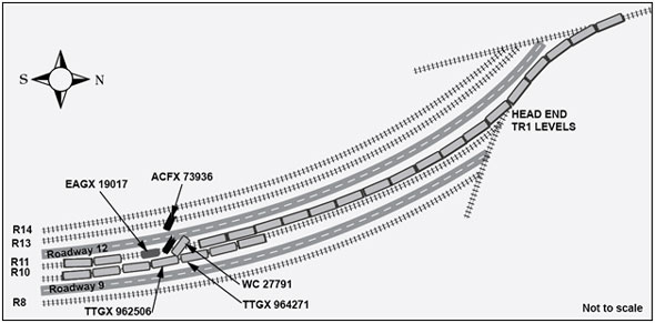
The conductor recharged the locomotive air brakes and at 0549:22 the assignment began to pull northward again. At 0549:58, after travelling about 100 feet, another transponder error occurred and the assignment came to a stop. Because the movement was unable to pull, the conductor was instructed by the yardmaster to shove back into track R-011. The conductor switched direction on the controlling unit and at 0552:06, the assignment began to shove the cars southward. At 0554:41, while travelling at 4 mph, another transponder error occurred which initiated a third automatic full service brake application. At 0554:56, after travelling southward for a total of about 600 feet, the assignment came to a stop and the Yardmaster informed the conductor that the assignment had derailed (see Figure 2). There were no injuries.

At the time of the occurrence, it was dark, with clear skies and good visibility. The temperature was -9.1°C and there was a 9 km/h northerly breeze.
Site examination
Subsequent inspection determined that the 16th and 17th cars from the locomotives had derailed near the north switch of track R-011. The A-end of the 18th car and 2 cars on an adjacent track sustained impact damage. The 17th car, dangerous goods (DG) tank car ACFX 73936, had failed catastrophically near the middle of the car and had broken into 2 sections (see Photo 1).

From the north switch, tank car ACFX 73936 had been shoved southward for about 600 feet. In the process, it released its entire load of approximately 57 000 litres (15000 US gallons) of ferric sulphate (UN 3264) along roadway 12 and the adjacent tracks. One half of the tank car came to rest on roadway 12 between tracks R-011 and R-013. The other half came to rest fouling roadway 12 and track R-013 (see Figure 3). Aside from product contamination, only sporadic tie damage was observed along track R-011 for about 600 feet.
Inspection of the hump set revealed that it had been set up for CN's Symington Yard in Winnipeg, Manitoba. The tank car was isolated and then moved to a shop in MacMillan Yard for examination by TSB Engineering Laboratory personnel.
Site remediation
Ferric sulphate (UN 3264) is classed as a corrosive liquid. It belongs to the family of inorganic salts and is also referred to as iron (II) sulphate. Ferric sulphate solution contains sulphuric acid and is used in water and waste water treatment.
Remediation efforts at the site of the tank car failure were extensive. Air quality monitoring was conducted to ensure site safety. During the remediation process, there was no detectable worker exposure to either ferric sulphate as soluble iron or sulphuric acid.
Approximately 3200 tons of contaminated ballast, ties and soil were removed from an area measuring 150 meters long and 50 meters wide. This excavated area required the removal of sections of tracks R-008, R-010, R-011, R-013 and R-014. About 30 000 litres of ferric sulphate solution was recovered.
Surface water and catch basin monitoring was conducted and 11 monitoring wells were installed to monitor potential migration of any residual product. Site monitoring determined that site remediation was successful and has since been discontinued.
Tank car ACFX 73936
ACFX 73936 was loaded with 88 681 kilograms (195 100 pounds) of ferric sulphate solution at Chinter, Illinois on 22 January 2010 destined for MacMillan Yard, Toronto, Ontario. The car arrived at destination on 08 February 2010 and yarded in track R011 at 2105. Upon its arrival, the car received an inbound Certified Car Inspection (CCI), in accordance with the Transport Canada (TC) Railway Freight Car Inspection and Safety Rules. No defects were noted.
ACFX 73936 was a 100 ton (263K) non-pressure, non-jacketed, non-insulated, rubber lined, DOT111A100W5 tank car with a capacity of 20 800 US gallons. It was manufactured under Certificate No. A901024 in June 1990 by ACF Industries Inc., a company that is no longer in business. It was owned and maintained by GE Capital Rail Services and leased to Kemira Water SolutionsFootnote 4 which was responsible for the installation and maintenance of the rubber liner.
Typical of many non-pressure tank cars, the tank heads and shell had a nominal thickness of 7⁄16 inch. The tank head and end shell plates were manufactured from ASTM A516 Grade 70 non-normalized steel. The intermediate and center shell plates were made with AAR TC128 Grade B (AAR TC128-B) non-normalized steel. The tank was last qualifiedFootnote 5 in September 2000 and was due for qualification in September 2010. The liner was qualified in 2008.
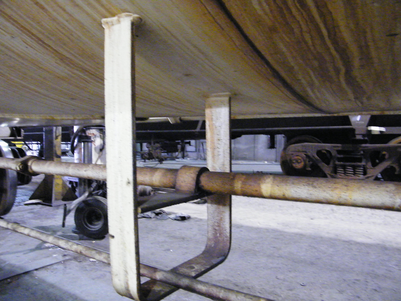
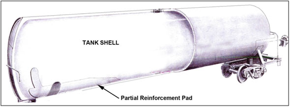
The car was assembled from steel plates which were welded together. Reinforcement pads (re-pads) and appurtenances had been welded in place as required. There were two large partial re-pads, each measuring about 15 feet long, welded onto the tank at each end. The tank car stub sills were welded onto these re-pads. Between the partial stub sill re-pads, there was a 12 foot long non-reinforced section. In this area, the tank car drawing called for a 1⁄4 inch fillet weld to secure a longitudinally oriented air brake pipe and rigging support bracket (the bracket) directly to the tank shell at two locations (inboard leg and outboard leg). The bracket which was made from 2 1⁄2 inch wide by 3⁄8 inch thick material (i.e., 5 3⁄4 inches of linear weld), was located about 20 feet from the A-end of the tank. The inboard leg was placed about 10 inches from the bottom center line of the tank car in an area of the tank shell that was not reinforced.
On-site examination of ACFX 73936
On-site examination revealed that the tank had failed in the centre shell portion of the tank car. Chevron marks were observed throughout the fracture surface circumference. The chevron marks pointed back to and identified a small semi-elliptical region at the bottom of the tank car as the fracture origin. The extent and orientation of the chevron features indicated that the tank failure propagated in a brittle and rapid manner, circumferentially in both directions, from the extremities of the fracture origin.
The fracture origin (crack #1) was located at the toe of a longitudinally oriented fillet weld which secured the inboard leg of the bracket to the tank shell (see Photo 2 and Photo 3). The fracture origin was oxidized and displayed beachmarks and ratchet marks typical of fatigue cracking. The fracture features indicate that multiple cracks initiated on the exterior of the tank shell and propagated into the shell material. The cracks combined into a single fatigue crack about 2 inches long and 5⁄16 inches deep (see Photo 4).

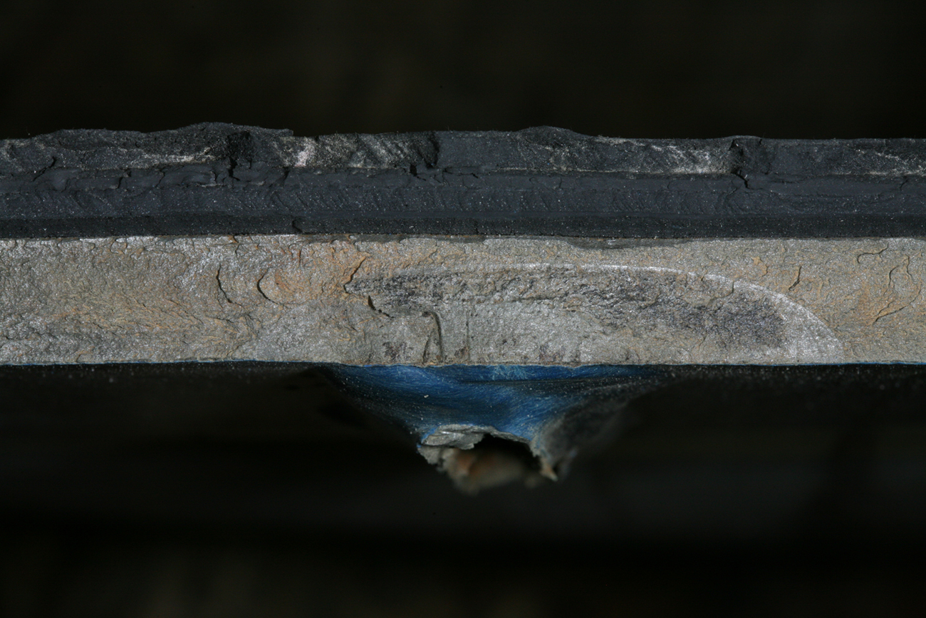
The tank liner was in good condition with no obvious degradation. The liner was well adhered to the tank shell interior. Portions of the ACFX 73936 shell containing the fracture surfaces were removed and forwarded to the TSB Engineering Laboratory for detailed analysis.
Tank car reinforcement pads and attachment of appurtenances
Tank car reinforcement pads (re-pads) provide localized reinforcement and skid protection for the shell as well as shear protection for appurtenances welded to them. This design feature is such that, in the event of a derailment, exposed appurtenances are meant to tear away from the re-pads and leave the tank shell intact. Each tank car is equipped with either:
- Continuous re-pads that are welded to the bottom and extend the entire length of the tank shell. Stub sills and various appurtenances are welded to the continuous re-pads; or
- Partial stub sill re-pads, otherwise known as non-continuous re-pads, to which the stub sills are welded (see Figure 4).
Additional re-pads are applied to the tank shell to accommodate the securement of various appurtenances as required by tank car design and specifications. In some circumstances, appurtenances are permitted to be welded directly to the tank shell.
While there are a number of configurations, partial stub sill re-pads generally have rounded or tapered ends. Partial stub sill re-pads are not continuously welded to the tank. There are gaps between lengths of weld beads that secure the re-pad to the tank. The end welds are oriented longitudinally and generally terminate about 9 inches from the bottom centerline of the tank car on both sides of the re-pad. This leaves a semi-circular non-welded area of the re-pad near the longitudinal centre of the car. In cases where reinforcement is not continuous, a region in the center of the tank car is unsupported, which leaves the tank shell directly subject to bending loads.
Fracture resistance of non-pressure tank car steel
The ability of a steel alloy to resist fracturing depends on its ductility which changes with the temperature of the steel. As the temperature drops, ductile steel becomes brittle and is more easily fractured. The temperature at which steel changes from ductile to brittle is called the ductile to brittle transition temperature. Ductile steel deforms before it fractures while brittle steel shows no evidence of deformation before failure.
Less impact energy is required to break steel when it is below its transition temperature than to break the same steel when it is above its transition temperature. A normalizing heat treatment is one method that is used to lower the transition temperature of steel and increase its impact resistance. However, normalizing alone may not be sufficient to prevent complete shell fractures.
Tank car information
Non-pressure tank cars in DG service transport large volumes of DG such as gasoline, aviation fuel, hexane, methanol, benzene dicyclopentadiene, peroxide, hydrochloric acid and sulphuric acid to name a few. Ferric sulphate also falls into this category. Non-pressure tank cars in general service transport large volumes of non-regulated products. While non-regulated products are considered less dangerous than regulated DG, non-regulated products may still be environmentally hazardous and toxic and cause widespread damage in the event of a release.Footnote 6
There is no life limit on a tank car tank if the tank conforms to both the federal regulations and Association of American Railroads (AAR) requirements. Underframes, which include the re-pads and stub sills, built since 01 July, 1974, have an AAR life limit of 50 years.
The maximum gross rail load (GRL) established for tank cars in dangerous goods service is 263 000 pounds (263K). However, in 1999, Transport Canada (TC) and the United States Department of Transportation's (DOT) Federal Railroad Administration (FRA) issued a joint “White Paper,” (TC/FRA White Paper) establishing additional design requirements under which permits and exemptions could be issued for new construction of non-pressure tank cars built to accommodate a GRL of 286 000 pounds (286K). The new requirements included improved puncture resistance sometimes achieved by using more puncture resistant construction material, half-head shields and improved roll-over protection. The new requirements do not apply to Class 111A tank cars with a gross weight of 263K even though these cars represent the vast majority of non-pressure tank cars both in-service and/or newly constructed. Going forward, the industry is slowly moving to the larger 286K capacity cars.
Within the North American tank car fleet of approximately 314 000 cars, there are about 61 000 pressure tank cars. The remaining 253 000 tank cars are non-pressure tank cars in either general or DG service. Of these 253 000 tank cars, approximately 82 000 of them were built prior to September 1990, many of which have appurtenances welded directly to the tank shell.
Tank car standards
In North America, all facets of tank car construction, maintenance and qualification are governed by the following regulations and standards:
- TC's Transportation of Dangerous Goods Regulations, which adopts the Canadian General Standards Board (CGSB) National Standard of Canada CAN/CGSB-43.147–2005 which governs the “Construction, Modification, Qualification, Maintenance, and Selection and Use of Means of Containment for the Handling, Offering for Transport, or Transporting of Dangerous Goods by Rail” (CGSB Standard).
- The United States DOT, Code of Federal Regulations (CFR) Title 49: Transportation, Part 179 – Specifications For Tank Cars, Subpart D – Specifications for Non-Pressure Tank Car Tanks (49 CFR).
- The Association of American Railroads (AAR) Manual of Standards and Recommended Practices (MSRP), Section C-III, Tank Car Construction, Standard M-1002 (AAR M-1002 Standard)
By reference, the CGSB Standard and the 49 CFR regulations incorporate various parts of the AAR M-1002 Standard.
Structural integrity inspection
As part of the tank car qualification requirements, both the 49 CFR regulations and the CGSB Standard require that a structural integrity inspection be performed, which must include the termination of longitudinal fillet welds with design dimensions greater than 6 mm (1⁄4 inch) within 122 cm (4 feet) of the bottom longitudinal centerline. This includes stub sill re-pad welds. The requirements also identify non-destructive examination (NDE) methods which include direct and remote visual inspection as acceptable NDE methods. While there are a number of other approved NDE methods for conducting the structural integrity inspection, visual inspection tends to be the primary method of inspection for tank car qualification.
Requirements for use of re-pads
AAR M-1002 Standard, Appendix E, Design Details, Section 15.1 sets forth requirements for the use of re-pads. Section 15.1.1 states “Attachment requirements for major structural components are covered in the sections of the manual that deal with those components. For other brackets and attachments, re-pads are required, if, when welded directly to tanks, they could cause damage to the tanks, either through fatigue, over-stressing, or denting or puncturing in the event of an accident.” This requirement was implemented in September 1990.
For non-pressure tank cars constructed prior to September 1990, such as ACFX 73936, similar brackets could be welded directly to the tank shell provided that the weld measured 1⁄4 inch or less and was less than 6 inches in total linear length as specified on the drawing. The same criteria was stipulated in both CFR Part 179, Subpart D, Subsection 179.200-19 Reinforcements and CGSB-43.147–2005 Section 16.7 – Attachments.
Part II of the CGSB standard governs new construction and the modification of tank cars and ton containers for the transportation of dangerous goods by rail. In July 2008, section 16.7 - Attachments in the standard was amendedFootnote 7 to state that “b. Regardless of date built, reinforcing pads are required for (i.) any air brake equipment support attachments; and (ii.) any other bracket or attachment, regardless of weld length, if they could cause damage to the tank either through fatigue, over-stressing, denting or puncturing in the event of an accident.”
Material specification
AAR M-1002 Standard, Appendix M, Specifications For Materials, Section 1.2, Table M10.1 identifies that, for tank cars with a GRL of up to 263K, ASTM 516 Grade 70 or AAR TC128-B plate steels (non-normalized) may be used for non-pressure tank car fabrication. 49 CFR 179.200-7 and the CGSB Standard Subsection 16.3 have similar requirements. None of the federal regulatory provisions require the use of normalized steels in the construction of non-pressure tank cars or establish fracture toughness criteria for the material.
In comparison, the AAR M-1002 Standard, Section 2.2.1 outlines additional General Requirements for Pressure Tank Car Tanks and states (in part):
- “Section 2.2.1.1 – All steel, single-unit pressure tank car tanks must be fabricated from fine-grain steels as described by ASTM A516, A537 or AAR TC128-B. Heads and shells of pressure tank car tanks constructed of ASTM A516 or AAR TC128-B must be normalized, effective January 1, 1989.”
- “Section 2.2.1.2 - Effective for cars ordered after August 1, 2005, each plate-as-rolled of ASTM A516, A302, A537, and AAR TC128-B steel used for pressure tank car heads and shells must be Charpy impact tested transverse to the rolling direction in accordance with ASTM A20. The test coupons must simulate the in-service condition of the material and must meet the minimum requirement of 15 ft lb average for three specimens, with no single value below 10 ft lb and no two below 15 ft lb at minus 30°F (minus 35°C).”
The AAR M-1002 Standard was revised by the AAR in 2003, incorporating the provisions outlined in the TC/FRA White Paper. Section 2.5 was added to include additional requirements for DOT/TC tank cars weighing over 263K. This section states that such carbon steel non-pressure tank cars must:
- be equipped with top fittings protection in accordance with Appendix E, paragraph 10.2.
- be equipped with reclosing pressure relief devices, except where the applicant can demonstrate that a non-reclosing device affords an equivalent level of safety.
- have heads and shells constructed of normalized AAR TC128-B steel. Tank car heads must be normalized after forming, unless specific approval is granted for a facility's equipment and controls. Non-jacketed tanks must be at least 1⁄2 inch thick and be equipped with half-head shields. Jacketed tanks must be at least 7⁄16 inch thick and be equipped with 1⁄2 inch thick jacket heads.
Analysis of tank car ACFX 73936 failure
Detailed analysis of the tank car failure by the TSB Engineering Laboratory determined that:
- The inboard leg of the bracket was located near the bottom center line of the tank shell in an area that was not reinforced. In the absence of any reinforcing pad, the weld which secured the inboard leg of the bracket to the tank shell was subjected to higher in-service bending loads. These bending loads applied tensile stresses at the toe of the inboard bracket leg weld and initiated the fatigue crack (crack #1).
- Magnetic particle inspection (MPI) was performed around both welds that secured the bracket to the tank shell. A second crack (crack #2) was observed at the toe of the other end of the weld. No cracks were observed around the weld securing the second leg (outboard) of the bracket.
- Crack #2 was opened in the laboratory and examined. It exhibited two distinct semi-elliptical regions, with beachmarks typical of a fatigue crack. One region, which measured about 3⁄8 inches wide by 1⁄8 inch deep, was extensively corroded indicating that it had been present for some time.
- Both bracket leg fillet welds were larger than the manufacturer's specification of 1⁄4 inch. The failed weld on the inboard leg measured 3⁄8 inch while the weld on the outboard leg measured over 1⁄2 inch.
- Oversize welds can cause higher weld residual stresses due to the higher heat input. These residual stresses can reduce the fatigue strength of the joint.
- Fillet welds have reduced fatigue strength due to the stress concentration resulting from their inherent shape. Even fillet welds that carry no load can cause fatigue failure of the load carrying part. The fatigue strength of fillet welds is governed primarily by their external profile. Fatigue cracks typically initiate in the toe of the weld.
- Defects such as undercuts, toe cracks, slag inclusions and/or pores can act as additional stress concentrators. No material or welding defects were observed at the fracture origin.
- Metallurgical examination of the bracket welds identified martensite in the heat affected zones (HAZ). Brittle fracture has been known to initiate from a weld when it has a much higher hardness than the tank shell. However, the HAZ hardness was similar to that of the weld bead and only slightly higher than the shell plate hardness, indicating that the joint was well matched.
- The tank shell material met the applicable specifications for chemical composition, hardness and tensile properties. The room temperature yield strength and ultimate tensile strength of the shell material were determined to be 76 ksi and 101 ksi respectively. No metallurgical anomalies were noted in the shell material.
Charpy impact testing was performed in accordance with ASTM E23 on full size Charpy samples. Samples were tested in both the transverse and longitudinal orientation with the following results:- At 30°C, the average transverse impact energy was 24 foot pounds (ft-lbs) and the average longitudinal impact energy was 58 ft-lbs.
- At 0°C the average transverse impact energy was 14 ft-lbs and the average longitudinal impact energy was 42 ft-lbs.
- At -30°C the average transverse impact energy was 10 ft-lbs and the average longitudinal impact energy was 17 ft-lbs.
- The values obtained were consistent with previous testing conducted on non-normalized TC128 Grade B steel.Footnote 8 The testing demonstrated that the shell material had low fracture toughness in the transverse direction at temperatures of -0°C or colder. Such steels require little energy to propagate a pre-existing crack.
A sister tank car (ACFX 73937) was also examined at a certified tank car repair facility. Three sets of bracket welds, including the center bracket where the occurrence tank car cracking had initiated, were examined by a certified Non Destructive Evaluation (NDE) technician. The paint was removed from all six welds and both liquid penetrant and MPI inspection techniques were used. No cracking was found at any of the welds. However, the bracket leg weld sizes were also oversized measuring from 5⁄16 inch to over 1⁄2 inch.
National Transportation Safety Board investigation of derailment and release of anhydrous ammonia near Minot, North Dakota
On 18 January 2002, a Canadian Pacific freight train derailed in Minot, North Dakota, United States. As a result of the accident, 5 DG pressure tank cars loaded with Anhydrous Ammonia (UN 1005) sustained impacts and subsequently ruptured catastrophically releasing over 142 000 gallons (US) of product to atmosphere. The ambient temperature at the time of the accident was about - 5°F (-21°C). One person was fatally injured, 10 people sustained serious injuries and 322 people, including the 2 train crew members, sustained minor injuries. The National Transportation Safety Board (NTSB) investigation determined that the derailment was caused by cracked joint bars that completely fractured and led to broken rail at the joint.Footnote 9
During the Minot investigation, the NTSB conducted a metallurgical investigationFootnote 10 to determine the mode of failure of the 5 pressure tank cars and to quantify the impact resistance of the steel from the cars involved in the accident. Each of the 5 failed tank cars were DOT Class 105, jacketed and insulated pressure tank cars built prior to 1989. The tank shell of each car was constructed of non-normalized AAR TC128-B steel in accordance with AAR standards in place at the time of construction. NTSB Investigators removed material samples from the shells and subjected them to Charpy V-notch impact testing.
Metallographic examination of the coupons from the tank cars revealed that the rolling direction of the steel plates for the shell portion was parallel to the circumference of the shell. Charpy tests were performed on longitudinal (parallel to steel rolling direction) and transverse samples (perpendicular to steel rolling direction). Recorded impact values for transverse samples were typically lower than longitudinal samples. Based on the examination results, the NTSB concluded that the low fracture toughness of the non-normalized AAR TC128-B steel used for the tank shells of the 5 pressure tank cars contributed to their complete fracture and separation.
Subsequently, the NTSB recommended that the FRA:
- Conduct a comprehensive analysis to determine the impact resistance of the steels in the shells of pressure tank cars constructed before 1989. At a minimum, the safety analysis should include the results of dynamic fracture toughness tests and/or the results of non-destructive testing techniques that provide information on material ductility and fracture toughness. The data should come from samples of steel from the tank shells from original manufacturing or from a statistically representative sampling of the shells of the pre-1989 pressure tank car fleet. (R-04-4)
- A study of the “Mechanical Properties of Tank Car Steels Retired from the Fleet” was conducted and published in June 2007.Footnote 11
- Develop and implement tank car design-specific fracture toughness standards, such as a minimum average Charpy value, for steels and other materials of construction for pressure tank cars used for the transportation of U.S. Department of Transportation class 2 hazardous materials, including those in low-temperature service. The performance criteria must apply to the material orientation with the minimum impact resistance and take into account the entire range of operating temperatures of the tank car. (R-04-7)
- The AAR subsequently revised its AAR M-1002 Standard to include such requirements for pressure tank cars ordered after 01 August 2005.
While both recommendations were focussed on pressure tank cars, most non-pressure tank cars are constructed from, and continue to be built with, non-normalized steel that has the same material properties as the steel referenced in the investigation and subsequent study.
Study on “Mechanical properties of tank car steels retired from the fleet”
The Southwest Research Institute (SwRI) conducted an extensive testing program to satisfy NTSB Recommendation R-04-4 and documented the results in a report. The report identified that it is likely that static strength and fracture toughness play an important role in controlling whether rupture and puncture occur, although how the two contribute to the failure behaviour is not yet fully understood. The report presented test results that characterized the basic material properties of AAR TC128-B samples extracted from retired pre-1989 (non-normalized) and post-1989 (normalized) pressure tank cars that were selected to be representative of the fleet. The vast majority of samples (97%) met the current AAR TC128-B specification for elemental composition whereas 82% of samples met the tensile property requirements. There was no clear trend between chemical or tensile properties and the tank car build date.
Charpy v-notch (CVN) testing was conducted on a range of samples in an effort to measure material toughness. The tests were conducted at 0°F and -50°F (-18°C and -46°C), and results ranged from less than 10 ft-lbs to more than 40 ft-lbs. The testing results yielded a large amount of scatter with no discernible pattern which prevented definitive conclusions from being made with regards to fracture toughness variations and age of the material.
The SwRI report described the results of non standard, high rate (dynamic) fracture toughness tests and pendulum impact tests developed to quantify the puncture behaviour of the tank car steel. The test methodology was non standard and intended to represent behaviour during head or shell puncture and/or under large dynamic forces such as those which occurred in the Minot derailment. The tests were conducted at 0°F and -50°F (-18°C and -46°C) and gave values ranging from about 30 to 150 ksi√inFootnote 12. The dynamic fracture toughness results were somewhat higher than expected. It was considered that this was a consequence of the plastic behaviour (deformation) exhibited by the material under the selected test conditions.
The SwRI report also referenced a framework for interpreting static fracture toughness values that was based upon existing design codes for pressure vessels, bridges and other structures:
- 25 - 50 ksi√in = poor toughness
- 50 - 100 ksi√in = adequate toughness
- 100 - 200 ksi√in = good toughness
- >200 ksi√in = excellent toughness
Although most of the SwRI report was concerned with dynamic fracture toughness data, static fracture toughness data was also obtained for a range of AAR TC128-B samples. Where KIC is in ksi√in and CVN is in ft-lb, the following relationship was determined to provide a lower bound estimate linking the CVN energy of the steel to its static fracture toughness:
KIC=9.35(CVN)0.63
Using the CVN results recorded for the ACFX 73936 tank car steel, the following static fracture toughness values were obtained:
| Temperature (Celsius) | CVN (ft-lbs) | (ksi√in) |
|---|---|---|
| 0, -10, -20 | 14 | 49 |
| -30 | 10 | 40 |
Non-pressure tank car fracture stress calculations
When a structure contains a pre-existing crack, the stress at which failure occurs is referred to as the;residual strength. In these cases, the mode of failure will be either by net section yield or rapid propagation. Fracture mechanics analysis of tank car ACFX 73936 determined that, for the crack length at the time of the occurrence, failure would occur by net section yield at about 76 kilo pounds per square inch (ksi)Footnote 13 or by rapid propagation at about 18 ksi. Since the shell failure propagated rapidly, the residual strength would be about 18 ksi which was substantially lower than the measured 76 ksi yield strength of the material (i.e., the value at which failure would have occurred had there been no crack). Failure by rapid propagation was also consistent with the cold temperature performance of steel with low fracture toughness.
Further calculations determined that the stress at the failure location due to dead weight was 3 ksi. To cause the failure, the stress imparted upon the tank at the failure location was calculated to be 15 ksi (i.e., 18 ksi – 3 ksi). It was determined that in order to cause a stress of 15 ksi at the fracture location, the draft force on the coupler was approximately 232 kips. A value of 232 kips is considered moderate and well within tank car design criteria as the fatigue spectrum used in the design of tank cars includes loads as high as 410 kips.Footnote 14
TSB investigation of accident near Lévis, Quebec
On 17 August 2004, 18 tank cars of Canadian National train U-781-21-17, a petroleum product unit train, travelling from Lévis, Quebec to Montréal, Quebec, derailed at Mile 3.87 of the Lévis Subdivision. As a result of the accident, a number of non-pressure tank cars sustained damage and released approximately 200 000 litres of gasoline and diesel fuel into the area (TSB Report R04Q0040).
The tank cars involved in the derailment were uninsulated, non-pressure tank cars built to specification DOT 111A100W1. The cars were constructed in 1995 and 1996. The tank shells and heads were constructed with 7⁄16 inch TC-128 Grade B non-normalized steel. The cars were not equipped with head shield protection. The construction certificate indicated that they were built for a maximum 286K GRL. However, they were limited to carrying 263K GRL.
The report identified that the maximum GRL established for tank cars in dangerous goods service is 263K. However, it is possible to seek permission from federal regulators (US DOT/FRA or TC) by way of applications for an exemption or permit for the construction of non-pressure tank cars built to accommodate a GRL of 286K, based on the supplementary design elements outlined in the FRA/TC White Paper. These additional design elements have since been integrated into the AAR M-1002 Standard. Since 2003, in Canada, TC has also required all non-pressure cars carrying more than 263K to meet these supplementary provisions, which include higher puncture resistance through the use of normalized steel, half-head shields and improved protection of service equipment such as valves. However, the safety enhancements provided by these supplementary provisions do not apply to non-pressure tank cars with a maximum GRL of 263K or less even though they represent the vast majority of recently built tank car population.
Consequently, a large number of the existing non-pressure tank cars carrying dangerous goods remain vulnerable to puncture and failure even during derailments at moderate operating speeds.
Considering that the difference in product volume between a 263K tank car and a 286K tank car is less than 9%, the risks presented by a product release would not be significantly lower for a 263K car. Therefore, the Board recommended that:
The Department of Transport extend the safety provisions of the construction standards applicable to 286 000 pound cars to all new non-pressurized tank cars carrying dangerous goods.
Transportation Safety Recommendation R07-04
TC acknowledged the deficiency and indicated that it is following up with tank car stakeholders in North America. The Board assessed TC's response to the recommendation as having “Satisfactory Intent”. TSB continues to monitor the industry for progress on this issue.
Other related tank car failures
On 13 February 2010, at 0845, a Canadian National (CN) employee reported product leaking from non-pressure tank car NATX 76364 in track C-079 at CN's MacMillan Yard in Toronto, Ontario. The car was carrying light cycle oil (UN 1993). The car was isolated, off-loaded and transported to a certified repair shop for inspection (TSB Occurrence R10T0053). The car was last qualified in 2005. The TSB Engineering Laboratory conducted a detailed analysis of tank car NATX 76364 which revealed that:
- The primary crack (crack #1) initiated on the B-end, in the toe of an undercut fillet weld defect at the termination of one of the longitudinally oriented end welds securing the partial stub sill re-pad to the tank shell. The fracture surface was heavily oxidized suggesting it had been present for some time prior to the occurrence.
- The crack was about 3 inches long, had progressed in fatigue, then propagated through the plate thickness in a brittle overstress mode which resulted in the leak.
- Additional fatigue cracks, which were not visible during the visual examination, were observed at the ends of the 3 other stub sill re-pad fillet welds. All 3 of these fatigue cracks were tightly closed and covered with corrosion on the tank shell surface.
- The car was constructed with ASTM A-515 Grade 70 non-normalized steel which has similar properties to AAR TC 128 Grade B non-normalized steel. Charpy impact testing was performed in accordance with ASTM E23 on full size Charpy samples. Samples were tested in both the transverse and longitudinal orientation with similar results. At 30°C, the material recorded average transverse impact energy of 38 ft-lbs while at −10°C the average transverse impact energy recorded was 9 ft-lbs. The low transverse fracture toughness at temperatures below −10°C is consistent with the behaviour expected from this type of steel.
Since 2005, in Canada and the United States, there have been 4 catastrophic failures of non-pressure tank cars (see Appendix A) and cracking resulting in the release of product was observed in at least 3 non-pressure tank shells (see Appendix B). There were a number of similarities for each of these failures:
- Each car had a GRL of 263K and was loaded at the time of the reported failure.
- The cars involved were approximately 20 years old or older and equipped with partial stub sill reinforcing pads that did not extend the full length of the car.
- A long portion in the center of the tank car was unsupported. This unsupported portion had been subjected to higher bending loads during operation which applied tensile stresses to the toe of longitudinally oriented fillet welds.
- Small fatigue induced pre-existing cracks had initiated at the toe or termination of one or more longitudinally oriented fillet welds that secured either an appurtenance or the end of a partial re-pad to the tank in an area near the bottom centre line of the tank car.
- Brittle overstress fractures had initiated from the extremities of the small fatigue cracks. In the case of the 4 catastrophic failures, the brittle overstress fractures propagated circumferentially (transverse) around the tank resulting in tank separation. The temperature at the time of failure was − 2°C or colder.
- The cars were constructed with non-normalized steel that is known to have a reduced transverse fracture toughness in cool temperatures.
Next generation tank car
Since 2001, a number of high profile rail accidents have heightened awareness of safety and security issues related to the transportation of DG by rail. Subsequently, the rail industry which includes regulators, industry organizations, shippers, car builders and railways have refocussed their efforts to improve the safety and initiated the “Next Generation Tank Car” project. Initially, the project focussed on the construction standards of pressure tank cars used to transport the more hazardous DG. This was primarily in response to several NTSB rail accident reports and the subsequent recommendations.
More recently, in response to several accidents in the United States and TSB Recommendation R07-04, more attention has been focussed on the need for improved non-pressure tank car standards. There is recognition within the industry of the need for a new general service tank car standard with improved safety features. To that end, there has been discussion about applying the more stringent AAR provisions for 286K non-pressure tank car construction to the next generation of newly constructed 263K non-pressure tank cars. However, progress has been slow and no firm decision has been made.
The following TSB Engineering Laboratory reports were completed and are available on request:
- LP018/2010 - Tank Car Failure (ACFX 73936)
- LP185/2010 - Tank Car Fracture Stress Calculation (ACFX 73936)
- LP053/2010 - Tank Car Failure (NATX 76364)
Analysis
The investigation did not reveal any deficiencies with regards to car loading, track structure or train handling which could be considered causal. The analysis will focus on the failure of non-pressure tank car ACFX 73936 as well as tank car construction and maintenance issues.
The accident
Damage observed along Roadway 12 and Track R-011 as well as the position in which the derailed cars came to rest showed that the derailment had occurred when the 17th car, DG non-pressure tank car ACFX 73936 loaded with ferric sulphate (UN3264), failed catastrophically near the middle of the car, and broke into 2 sections near the north switch of track R-011. As the assignment was shoved a further 600 feet southward, the failed tank car released its contents along Roadway 12 and the adjacent tracks.
Assignment operation and hump pull-back protection
While in operation, if a hump set encounters an unknown transponder or if GPS coordinates at that time do not align with those recognized by the locomotive, an error will occur and the engine will automatically be brought to a controlled stop. Because the hump set had been inadvertently set up for CN's Symington Yard in Winnipeg, it initiated transponder errors as it passed over the transponders imbedded along the track. The CN hump pull-back protection system worked as designed and each time a transponder error occurred, a service brake application brought the assignment to a controlled stop.
Fracture mechanics analysis of tank car ACFX 73936 determined that the stress imparted upon the tank at the failure location was about 15 ksi. In order to cause a stress of 15 ksi at the fracture location, the draft force on the coupler was calculated to be approximately 232 kips, a moderate value well within tank car design criteria. It is also possible that hydraulic action from product movement within the tank played a role in the accident. Had this been the case, the draft forces acting on the coupler would have been even lower than the estimated 232 kips. A review of recorded information and TSB fracture mechanics analysis determined that the assignment was controlled in a manner consistent with normal yard switching operations and did not initiate any unusual dynamic forces.
Failure of non-pressure tank car ACFX 73936
The tank shell material met the chemical, hardness and tensile specifications with no metallurgical anomalies observed. Examination determined that the fracture originated at the toe of a longitudinally oriented fillet weld that secured the inboard leg of the bracket directly to the tank shell. The fracture origin was oxidized, indicating that it had been present yet undetected for some time, and displayed surface features consistent with fatigue cracking. These features indicated that multiple cracks had initiated at the toe of the weld on the tank shell exterior, propagated into the shell material and combined to form a small fatigue crack about 2 inches long and 5⁄16 inches deep. Because the fatigue crack depth was less than the shell plate thickness, the tank did not leak prior to failure. The tank separation occurred under normal service conditions when the shell failed circumferentially, in brittle mode, from the extremities of the small fatigue crack.
Reinforcement pads for air brake equipment support attachments
Since September 1990, the AAR M-1002 Standard has required brackets to be secured to re-pads. If a re-pad is not used, the brackets could cause damage to the tanks, either through fatigue, over-stressing, denting or puncturing in the event of an accident. For non-pressure tank cars constructed prior to September 1990, such as ACFX 73936 (built June 1990), brackets could be welded directly to the tank shell provided that the weld measured 1⁄4 inch or less and was less than 6 inches in total linear length as specified on the drawing. For tank car ACFX 73936, the drawing called for a 1⁄4 inch fillet weld to secure a bracket made from 2 1⁄2 inch wide by 3⁄8 inch thick material (i.e., 5 3⁄4 inches of linear weld).
Since the fillet weld specified met the linear requirements in effect at the time of tank car construction, a re-pad was not required under the bracket. Consequently, the bracket was welded directly to the tank shell near the middle of the car about 20 feet from the A-end of the tank with the inboard leg placed about 10 inches from the bottom center line of the tank in an area of the shell that was not reinforced. In the absence of a reinforcing pad, the longitudinal fillet weld which secured the bracket's inboard leg to the tank shell near the centre line of the car was subjected to higher in-service bending loads. These bending loads applied tensile stresses at the toe of the weld and initiated the fatigue crack.
The precise number of tank cars with arrangements similar to ACFX 73936 is unknown. However, there are about 82 000 non-pressure tank cars in-service that were built prior to September 1990, many of which have appurtenances welded directly to the tank shell. To address this issue, the CGSB Standard was amended in July 2008 by way of Amendment No. 1 (implemented March 2011) to require the use of re-pads on tank cars, for any air brake equipment support attachments, for new car construction. This is a positive step towards mitigating deficiencies similar to those that contributed to the failure of tank car ACFX 73936. The revised CGSB standard is consistent with the present AAR M-1002 Standard but there is no equivalent requirement in the 49 CFR regulations. Furthermore, the standards do not require non-pressure tank cars that were built prior to September 1990 to be more frequently inspected in the suspect area or retrofitted with re-pads under any appurtenances that are welded directly to the shell. The lack of harmonization of tank car standards represents compliance and enforcement challenges that can, at times, be confusing and present a safety risk. Without consistent, harmonized standards requiring the use of re-pads for any air brake equipment support attachment, regardless of car built date, there is an increased risk of tank car failure for non-pressure, non-jacketed tank cars built prior to September 1990.
Tank car dteel fracture toughness
Under normal operating conditions, a non-pressure tank car should not fail catastrophically from a small fatigue crack. The shell steel should have sufficient fracture toughness to eliminate or minimize the risk of catastrophic brittle fractures under all operating conditions and in all environments. Ideally, if a tank car develops a small crack, the crack should be detected during the tank's qualification, before the integrity of the tank is compromised. If the crack goes undetected, in most cases it should cause the car to leak prior to causing a catastrophic failure. However, since 2005, there have been 4 similar catastrophic failures of non-pressure cars that have originated from small fatigue cracks. In each case, the tank shell was constructed with the specified non-normalized steel known to have reduced fracture toughness properties.
The ACFX 73936 tank shell was fabricated from non-normalized AAR TC128-B steel. The catastrophic fracture of the tank shell occurred rapidly as a brittle fracture. Although the temperature at the time was only a moderate -9°C, the brittle fracture mode indicates that the tank shell steel was below the ductile-to-brittle transition temperature at the time of the failure. Charpy V-notch (CVN) testing confirmed that the shell material had low fracture toughness in the transverse direction at temperatures of 0°C or colder. Steel with such low fracture toughness requires little energy to propagate a pre-existing crack. Consequently, the low fracture toughness of the non-normalized AAR TC128-B steel, used to construct the ACFX 73936 tank shell, allowed the crack to propagate rapidly in brittle mode which contributed to the complete fracture and separation of the car.
As a result of the NTSB Minot investigation, a study of the Mechanical Properties of Tank Car Steels was conducted by Southwest Research Institute (SwRI). The testing results yielded a large amount of scatter with no discernible pattern. The scatter itself indicates that, although the tank car shells were constructed to the same standards, fracture toughness properties for the same steel can vary. The absence of consistent fracture toughness properties for tank car steel presents a risk that, although constructed to the same design standards, some tank cars may be more vulnerable to failure.
The pressure tank cars involved in the Minot accident were subjected to dynamic forces due to impacts sustained during the accident. Consequently, the SwRI report focussed primarily on dynamic fracture toughness of pressure cars. Since most non-pressure tank cars are constructed from, and continue to be built with, the same non-normalized steels as the 5 pressure tank cars that failed in Minot, conclusions drawn from the SwRI report are also relevant for non-pressure tank car steels. The report identified that static strength and fracture toughness both likely play an important role in controlling whether rupture and/or puncture occurs. A framework based on existing design codes was referenced for interpreting static fracture toughness values. The framework identified that values of 25-50 ksi√in had poor fracture toughness while values of 50-100 ksi√in had adequate toughness.
Tank car ACFX 73936 failed due to brittle overstress extension of a small pre-existing fatigue crack while subjected to service loads during normal yard operations. There was no denting, perforation or significant plastic deformation (necking) associated with the subject fracture. Hence, the relevant material property is considered to be more consistent with static fracture toughness, rather than the dynamic fracture toughness referenced in the SwRI and Minot reports. The temperature at the time of this occurrence was reported to be -9°C, which is considered an average winter temperature in many areas of North America. At the occurrence temperature, the static fracture toughness was calculated to be of 49 ksi√in. Using the SwRI framework for static fracture toughness, the ACFX 73936 non-normalized AAR TC128-B shell steel would be considered as only marginally adequate under the accident conditions.
The low fracture toughness and corresponding residual strength of the ACFX 73936 non-normalized AAR TC 128-B tank car steel was consistent with testing results reviewed from other tank car failures. Standards for pressure tank cars and non-pressure cars built to a capacity exceeding 263K GRL include fracture toughness criteria. In contrast, the current standards for non-pressure tank cars with a GRL of 263K (or less) have no established fracture toughness criteria even though they represent the vast majority of tank cars in the North American fleet. As demonstrated by at least 4 catastrophic non-pressure tank car failures, without improved materials standards that incorporate fracture toughness criteria for non-pressure tank shell steel, non-pressure tank cars constructed for a capacity of 263K (or less) have an increased risk of catastrophic failure in normal winter operating conditions.
Partial stub sill reinforcement pads
The end welds that secure partial stub sill re-pads to the tank shell are longitudinally oriented and terminate near the centerline of the tank on both sides of the re-pad. Because reinforcement is not continuous, a portion of the tank car shell remains unsupported in an area that is subject to bending loads during train operation. These bending loads apply tensile stresses to the ends of the re-pads, perpendicular to the longitudinal axis of the tank car and have the potential to initiate fatigue cracking at these locations.
In all 7 of the accidents reviewed since 2005, relatively small fatigue induced pre-existing cracks initiated at the termination of one or more longitudinally oriented fillet welds in an area of the tank that was unsupported and subject to bending loads. In 6 of the 7 cases, the fatigue cracks initiated at the toe of the end weld which secured a partial re-pad to the tank. In 3 of the 6 cases, brittle overstress fractures extended from the extremities of the pre-existing fatigue crack and resulted in catastrophic failure of the tank and a subsequent release of product. In the same time period, there has been no report of a catastrophic failure of a tank equipped with a continuous re-pad which is welded to the bottom and extends the length of the tank shell. Non-pressure tank cars equipped with partial stub sill re-pads have a greater risk of fracture and/or catastrophic failure when compared to those equipped with continuous re-pads.
Structural integrity inspection during tank car qualification
During tank car qualification, a structural integrity inspection must be conducted using one or more approved non-destructive evaluation (NDE) methods. The inspection includes stub sill re-pad welds. While there are a number of other approved NDE methods, direct and remote visual inspection tend to be the primary methods used for inspections.
Cracks appear to be more difficult to detect at the locations where they are more prone to develop in non-pressure tank cars equipped with partial stub sill re-pads. Examination of tank car NATX 76364 (Occurrence R10T0053) revealed that the primary crack initiated in the toe of an undercut fillet weld defect at the termination of a longitudinally oriented end weld securing the partial stub sill re-pad to the tank shell in an area near the bottom centre line of the tank car. The fracture surface was heavily oxidized indicating that it had been present for some time prior to the occurrence. Additional fatigue cracks, which were not visible during the shop visual examination, were observed during laboratory examination at the ends of the 3 other stub sill re-pad fillet welds. All of these fatigue cracks were tightly closed and covered with corrosion on the tank shell surface which made them difficult to detect during the visual shop inspection. Since 2005, similar cracks have been observed in at least 5 other non-pressure tank shells, 3 of which resulted in catastrophic tank failure.
Given the heavy oxidation observed on the NATX 76364 primary crack fracture surface, it is conceivable that the crack was present but undetected when the car was last qualified in 2005. This suggests that visual inspection alone may not be sufficient to detect cracks in these areas, particularly if surface corrosion is present and not removed prior to the inspection. An over-reliance on the visual inspection method alone for conducting structural integrity inspection during tank car qualification presents a risk that cracks, in longitudinal welds that secure partial stub sill re-pads to tanks, may not be consistently detected.
Weld size
For ACFX 73936, the finished fillet weld securing the inboard leg of the bracket to the tank shell met linear requirements, but measured from 3⁄8 to 1⁄2 inch in size. Similar oversize bracket welds were also observed on a sister car (ACFX 73937). This suggests that this condition may exist for other tank cars with similar arrangements. The AAR M-1002 Standard requires all welds greater than 1⁄4 inch to be inspected during tank car qualification. No inspection is required for welds smaller than 1⁄4 inch. This inspection criterion is based on the weld size specified on the drawing rather than the actual size of the finished weld. Consequently, similar oversize welds on any tank car do not require inspection during qualification. In the case of ACFX 73936, oxidation observed on the fatigue fracture surface indicated that the crack had been present for some time, at the toe of an oversize weld, and was detectable prior to failure. While the crack may not have been present when the tank was last qualified in September 2000, even if it were, it would have gone undetected as there was no reason to inspect it. Because the weld inspection criterion is based on specified rather than actual weld size, there is an increased risk that pre-existing cracks may go undetected during qualification.
Findings
Findings as to causes and contributing factors
- The derailment occurred when DG non-pressure tank car ACFX 73936, loaded with ferric sulphate (UN 3264), failed catastrophically near the middle of the car and broke into sections near the north switch of track R-011. Subsequently, the car released its contents along Roadway 12 and the adjacent tracks.
- Multiple cracks had initiated at the toe of a longitudinally oriented fillet weld that secured the inboard leg of an air brake pipe and rigging bracket directly to the tank shell exterior. The cracks propagated into the shell material and combined to form a small fatigue crack about 2 inches long and 5⁄16 inches deep.
- The tank separation occurred under normal service conditions when the shell failed circumferentially, in brittle mode, from the extremities of the small fatigue crack.
- In the absence of a reinforcing pad, the longitudinal fillet weld which secured the bracket's inboard leg to the tank shell near the centre line of the car was subjected to higher in-service bending loads. These bending loads applied tensile stresses at the toe of the weld and initiated the fatigue crack.
- The low fracture toughness of the non-normalized AAR TC128 grade B steel, used to construct the ACFX 73936 tank shell, allowed the crack to propagate rapidly in brittle mode which contributed to the complete fracture and separation of the car.
Finding as to risk
- Without consistent, harmonized standards requiring the use of re-pads for any air brake equipment support attachment, regardless of car built date, there is an increased risk of tank car failure for non-pressure, non-jacketed tank cars built prior to September 1990.
- The absence of consistent fracture toughness properties for tank car steel presents a risk that, although constructed to the same design standards, some tank cars may be more vulnerable to failure.
- Without improved materials standards that incorporate fracture toughness criteria for non-pressure tank shell steel, non-pressure tank cars constructed for a capacity of 263K (or less) have an increased risk of catastrophic failure in normal winter operating conditions.
- Non-pressure tank cars equipped with partial stub sill re-pads have a greater risk of fracture and/or catastrophic failure when compared to those equipped with continuous re-pads.
- An over-reliance on the visual inspection method alone for conducting structural integrity inspection during tank car qualification presents a risk that cracks, in longitudinal welds that secure partial stub sill re-pads to tanks, may not be consistently detected.
- Because the weld inspection criterion is based on specified weld size rather than actual finished weld size, there is an increased risk that pre-existing cracks may go undetected during qualification.
Other findings
- The CN hump pull-back protection system worked as designed and each time a transponder error occurred, a service brake application brought the assignment to a controlled stop.
- The assignment was controlled in a manner consistent with normal yard switching operations and did not initiate any unusual dynamic forces.
- Because the fatigue crack depth was less than the shell plate thickness, the tank did not leak prior to failure.
Safety action
Action taken
TSB Rail Safety Advisories
In May 2011, the TSB issued 3 Rail Safety Advisories (RSAs):
Rail Safety Advisory 05/11
The RSA identified that in the absence of any reinforcing pad, the oversized weld which secured the bracket to the tank shell was subjected to higher in-service bending loads which applied tensile stresses at the toe of the bracket weld and initiated the fatigue crack. While the size of the weld may have played a role in the failure, it is also likely that its longitudinal orientation and location near the centre line of the car in the absence of a re-pad were contributory. Given the risk of failure for non-pressure tank cars with such arrangements, the RSA suggested that Transport Canada (TC), in conjunction with United States railroad regulators, may wish to review requirements for the application of re-pads to non-pressure, non-jacketed tank cars constructed prior to September 1990.
Transport Canada's response, dated 23 June 2011, stated that given the high number of tank cars and the interoperability of this large fleet throughout North America, TC's Transportation of Dangerous Goods Directorate (TDG) has asked the Association of American Railroads (AAR) Tank Car Committee (TCC) to create a new discussion docket to review and address the recent tank car failures having the characteristics of those identified in this TSB advisory letter. This issue was incorporated into the agenda of the AAR TCC meeting in Chicago in July 2011. In this manner, all key stakeholders, including TC, the AAR, the Federal Railroad Administration (FRA) and major fleet owners had the opportunity to discuss together and develop the most appropriate course of action.
TC proposed a number of safety actions for discussion in the docket with the aim of reducing the risks of such failures on older non-pressure tank cars. The actions include, as part of the current Qualification requirements set out in Part III of the CGSB43.147 standard, that the owners of these tanks cars address this particular risk failure by increasing the inspection frequency and efficiency for these attachments which could include the use of high probability detection techniques and procedures. The possibility of retrofitting small or large reinforcing pads, in combination with reinforcement applied to the bottom center portion of these tank cars where the overall stresses are the highest, was also discussed.
In Canada, the CGSB-43.147-2005 standard had been amended in July 2008. As noted in the report, regardless of date built, the changes require new tanks built to new TC specifications to have reinforcement pads for air brake equipment support attachments for non-pressure and non-jacketed tanks. TDG will publish additional changes to the TC Standard on Containers for the Transport of Dangerous Goods by Rail that will require reinforcement pads for air brake equipment support attachment on all non-pressure and non-jacketed tank cars operating in Canada once the standard is in force.
Rail Safety Advisory 06/11
The RSA identified that since 2005, there have been 4 catastrophic failures of non-pressure tank cars. In each of the 4 failures, the material properties of the non-normalized steel used for manufacturing the non-pressure tank cars met specifications in place at the time of car construction. However, the cars still failed catastrophically, in brittle mode, from small pre-existing fatigue cracks at a temperature of -9°C or colder.
Unlike the standards for pressure tank cars, none of the standards for non-pressure cars require the use of normalized steels in the construction of non-pressure tank cars or establish a fracture toughness standard for the material. Given the risk of non-pressure tank failure, especially during normal winter operating temperatures, the RSA suggested that Transport Canada, in conjunction with United States railroad regulators, may wish to review the applicable standards and establish fracture toughness criteria for the material used in the construction of non-pressure tank cars.
TC's response, dated 23 June 2011, stated that TDG examined this and the other tank car failures mentioned in the appendix to the RSA to address the safety issue raised by the TSB. TDG agreed that an improvement of the fracture toughness of steels used in the construction of non-pressure tank cars is warranted. TDG and the FRA were part of an AAR task force that was tasked to identify safety enhancements that could be made to new non-pressure tank cars to improve their accident survivability and safety in general. TDG requested the Task Force to extend the inclusion of all the safety enhancements currently required for tank car operating at increased gross rail loads (GRL 286 000 lbs vs 263 000 lbs) to all new non-pressure tank cars.
The task force agreed and the AAR has petitioned the Canadian and United States regulators to adopt it in their respective regulations. These suggested enhancements include the mandatory use of normalized steel when carbon or low alloy steels are used in the construction of the tank car's shell and heads. The use of normalized versus as-rolled steel will be an important enhancement for the fracture toughness of steel used for non-pressure tank cars.
TDG expects to table the AAR petition at the next meeting of the committee overseeing the soon to be published TC standard on the Containers for Transport of Dangerous Goods by Rail. In addition to normalizing, TC will also be introducing for discussion specific fracture toughness requirements which could take the form of additional Charpy test requirements for the steels used in the construction of the tank cars and/or potentially assigning tank cars with a minimum service temperature, with materials of construction having to meet certain fracture toughness requirements at that temperature.
Rail Safety Advisory 07/11
The RSA identified that non-pressure tank car NATX 76364 was discovered leaking product in track C-079 at CN's MacMillan Yard. Examination revealed that a crack had initiated in the toe of an undercut fillet weld defect at the termination of one of the longitudinally-oriented end welds securing the partial stub sill re-pad to the tank shell. The fracture surface was heavily oxidized suggesting it had been present for some time prior to the occurrence. Laboratory examination revealed that additional fatigue cracks, which were not visible during the shop visual examination, were observed at the ends of the 3 other stub sill re-pad fillet welds. These fatigue cracks were tightly closed and covered with corrosion on the tank shell surface which made them difficult to detect by visual inspection alone.
Visual inspection tends to be the primary method of inspection for tank car qualification. However, visual inspection alone is unlikely to detect cracking similar to that found on the tank car, particularly if surface corrosion is present and not removed prior to the inspection. Given the risks associated with cracks that compromise a tank shell, the RSA suggested that Transport Canada, in conjunction with United States railroad regulators, may wish to review the suitability of the existing visual method for inspecting welds that secure partial stub sill re-pads to non-pressure tanks.
TC's response, dated 8 July 2011, stated that TDG examined this and the other tank car failures mentioned in the appendix to the RSA to address the safety issue raised by the TSB. TDG believes that a visual inspection method alone of the fillet weld terminations on tank cars equipped with stub sill pads having the features of NATX 76364 could not conform to the requirements for structural integrity inspection in Standard CGSB-43.147-2005 as amended in July 2008. Since cracks can originate from stub sill to pads fillet weld attachment terminations and progress in the tank underneath the pads, the probability of detecting such cracks with a visual inspection method alone remains a concern for TDG. Therefore TDG officials will closely monitor the performance of structural integrity inspections at tank car facilities in Canada, paying close attention to the methods and techniques used for inspecting the welds identified in this RSA and verify that they are adequate for the performance of structural integrity inspections. TDG officials will continue to work with the appropriate United States regulators on this matter as well as explore other remedial actions that could potentially be appropriate for other tank cars having similar characteristics to NATX 76364.
Federal Railroad Administration
It is the opinion of FRA that the existence of fillet welds of a certain size, attaching brackets to the tank shells, represents a potential threat to the integrity of the tank shell. Unfortunately, there is often a discrepancy between the design size and as-built size of the welds where the as-built welds exceed the maximum size allowed by the regulations. FRA will work with the Association of American Railroads (AAR) to communicate with all tank car owners and facilities that on non-jacketed, general purpose tank cars, all fillets welds within 4 feet of the bottom centerline of the tank connecting attachments to the tank must be gauged to determine if the as-built size of the weld is compliant with regulations. If the weld is not compliant the tank car owner has two options:
- Apply a pad to the tank under the bracket.
- Apply for a Special Permit to allow continued use of the tank car.
A request for a Special Permit will require a detailed engineering analysis to demonstrate the integrity of the tank shell, as well as an inspection procedure using methods with the greatest sensitivity and intervals frequent enough to identify defects prior to growth to critical dimensions.
Concurrently, FRA has assembled a quality assurance team whose members have extensive experience in tank car construction and repair. This team has been charged with auditing every registered and certified tank car facility at least once over a 3-year period. Since its inception in May of 2010, the team has audited nearly half of the 340 tank car facilities. Based on the audit results, it is evident that there are significant deficiencies in both the inspection programs provided by tank car owners and the execution of the programs by tank car facilities. To quantify our findings, to date, over 30 facilities have withdrawn their registration and nearly 300 tank cars have been recalled because of noncompliant practices. One of the messages carried by the team to each of the facilities is the importance of development and close adherence to detailed inspection and repair procedures. While the facilities do not necessarily develop the procedure, they must be able to recognize compliant procedures and request additional information to ensure that the tank cars they qualify have been inspected per the requirements of the regulations.
Another FRA initiative is quantifying the NDE capabilities of the tank car facilities. FRA has an ongoing research project aimed at developing a probability of detection (POD) curve for all of the NDE methods. A POD curve indicates the likelihood that a defect is identified based on its size. The typical trend is that as the size of the defect increases, there is a commensurate increase in the probability that it will be detected. By recruiting personnel from the major tank car builders and repair facilities, the FRA has developed a POD curve for the different NDE methods.
Tank car facilities are required to have a Quality Assurance Program with “procedures for evaluating the inspection and test methods employed, including the accessibility of the area and sensitivity and reliability of the inspection and test technique and minimum detectable crack length.” [49 CFR § 179.7(b)(1O)] This requirement is meaningless unless there is a standard against which a particular facility's capabilities can be compared. For example, a facility can determine a minimum detectable flaw size, using a particular NDE method, to be 12 inches with a POD of 75 percent. The facility has complied with the regulations by determining its capabilities, but without an industry (standard) POD curve, their relative capability is unknown. It is the intent of FRA to use the industry POD curve in a future rulemaking that will assign allowable inspection intervals to NDE methods based on the sensitivity and POD curve of the methods; the greater the sensitivity, the longer the inspection interval.
The FRA initiatives outlined above, have been conceived to address longstanding and pervasive issues related to the quality of inspection and repair of tank cars. The FRA believes these initiatives will result in sweeping, fundamental changes that will ultimately address the issues outlined in the TSB's report and Rail Safety Advisories.
Association of American Railroads
The AAR Tank Car Committee (TCC) continually updates the specifications for steels contained in AAR standard M-1002 and AAR will ensure that a fracture toughness requirement is considered. The AAR notes that a universal normalization requirement is not necessarily desirable. The TCC is investigating the use of several types of steel that do not require the normalization process to achieve a high level of performance.
The AAR supports the use of higher sensitivity NDE methods for tank qualification, particularly with respect to the inspection of welds located near the bottom centerline of the tank where the highest stress gradients exist. The AAR is developing a circular in the near future recommending the use of an inspection method of higher sensitivity and focused inspections for the welds on non-continuous bottom reinforcing pads.
The AAR indicated that Railway Supply Institute members have agreed to sample their tank car fleets equipped with brackets welded directly to the tanks to determine whether there are cracks originating at the welds. The AAR TCC will mandate any maintenance required based on the results of the inspections, including the appropriate method of Non Destructive Examination (NDE).
General Electric Railcar Services Corporation
General Electric Railcar Services Corporation (GE) began specifying normalized steel for the construction of its general purpose tank cars in 2001. At present the GE Rail fleet includes over 3,900 general purpose tank cars constructed of normalized steel.
GE requires the use of magnetic particle inspection on certain inboard sill pad longitudinal weld terminations during qualification. The qualification program changes were the result of leveraging GE inspection data and service history.
Immediately after this incident all sister tank cars (17) listed on the tank car certificate of construction were visually inspected in the field or shop with no cracks found in the bracket attachment welds.
Working with Alltranstek, GE developed a procedure for the inspection of brackets welded directly to the tank shell using both magnetic particle and liquid penetrant inspection methods. This procedure was qualified by a Level III NDT Specialist in January of 2011.
GE Rail Engineering reviewed its fleet of non-insulated tanks built by ACF and identified the largest lots built with brackets welded directly to the tank (similar to ACFX 73936). As a result of this review, an inspection program was created to assess the condition of these bracket attachments using penetrant and magnetic particle testing methods. The inspection program includes 1156 cars (DOT111A100W1 and DOT111A100WS) manufactured between 1974 and 2007. These cars are being inspected as they are shopped for repairs or lease reassignment. The results of this inspection program will be shared with the AAR Tank Car Committee in October 2011 under Executive Committee Docket T45.72. The Committee has agreed to refrain from making any decisions on inspection requirements or pad application retrofits until potential fatigue issues related to bracket attachment welds is better understood. GE has committed to sharing this same inspection data with the TSB as the investigation continues.
GE Rail is working closely with regulators, the AAR and industry associations in the United States to insure the full rail industry is completely aware of this issue, the fleet-wide implications of it and the response that GE is taking to mitigate risk in its fleet.
This report concludes the Transportation Safety Board's investigation into this occurrence. Consequently, the Board authorized the release of this report on .
Appendices
Appendix A – Catastrophic tank car failures 2005-2010
| Car # | Fail date & temp at time | Place | Product | Tank spec. | MFGRMth/yr blt | Head & shell material | Accident temp charpy value ft-lbs | Min charpy temp deg C | Min charpy value ft-lbs | Notes on fracture origin |
|---|---|---|---|---|---|---|---|---|---|---|
| ACFX 73936 | Feb 9, 2010 −9°C | Toronto ON - CN Mac Yard | Load Ferric Sulfate (UN 3264) | 111A100W5 | ACF Jun 90 | Head Mat ASTM A-516 Gr 70 Non-Normalized Shell Mat TC 128 Gr B Non-Normalized | 14 | -30 | 10 | Broken in half near middle of car 1 small fatigue pre-existing fatigue crack originating at the toe of a longtitudinally oriented fillet weld which secured an air brake pipe and rigging bracket directly to the tank, near the middle of the car. Small fracture origin 2" wide x 3/16". Brittle over stress fractures initiated from extremities of the fatigue crack and propagated around the tank causing the tank to separate. |
| OWIX 15055 | Mar 5, 2008 -23 C | St. Paul Mn USA | Load Ethylene Glycol (UN - N/A) | Jacketed 111A100W1 | RTC & Trinity Jan 70 | Head Mat ASTM A-516 Gr 70 Non-Normalized Shell Mat TC 128 Gr B Non-Normalized | 3 | N/A | N/A | Broken in half near middle of car Extended re-pad - 2 small separate fatigue cracks (0.15-0.17" deep and 0.78 - 0.81" wide) originated at the terminations (toe) of longitudinally oriented fillet weld securing a partial longitudinal re-pad to the tank near the middle of the car. Brittle over stress fractures initiated from extremities of the fatigue cracks and propagated around the tank causing the tank to separate. |
| PTLX 120231 | Jan 11, 2005 −20°C | Calgary AB | Load Calcium Chloride (UN N/A) | 111A100W1 | RTC & Trinity Jul 74 | Head Mat ASTM A-516 Gr 70 Non-Normalized Shell Mat TC 128 Gr B Non-Normalized | N/A | N/A | N/A | Broken in 2 pieces near B-end Partial stub sill repad – 2 small separate fatigue cracks originated at the terminations (toe) of longitudinally oriented fillet weld securing the B-end partial stub sill re-pad to the tank, near the B-end of the car. Brittle over stress fractures initiated from the extremities of fatigue cracks and propagated around the tank causing the tank to separate. |
| UELX 78044 | Jan 12, 2005 −9°C | Milford UT USA | Load Alcohol (UN 1987) | 111A100W1 | ACF Jan 77 | Head Mat ASTM A-516 Gr 70 Non-Normalized Shell Mat TC 128 Gr B Non-Normalized | N/A | N/A | N/A | Broken in 2 pieces near B-end Partial stub sill repad – Fatigue crack originated at the termination (toe) of longitudinally oriented fillet weld securing the B-end partial stub sill re-pad to the tank, near the B-end of the car. Brittle over stress fractures initiated from the extremities of the pre-existing fatigue crack and propagated around the tank causing the tank to separate. |
Appendix B – Cracked tank cars 2005-2010
| Car # | Fail date & temp at time | Place | Product | Tank spec. | Mth/yr blt | Head & shell material | Accident temp charpy value ft-lbs | Min charpy temp deg C | Min charpy value ft-lbs | Notes on fracture origin |
|---|---|---|---|---|---|---|---|---|---|---|
| NATX 76364 | Feb 13, 2010 −5°C | Toronto ON – CN MacMillan Yard | Load Light Oil (UN 1993) | Jacketed 111A100W1 | NACC Dec 73 | Head Mat ASTM A-515 Gr 70 Non-Normalized Shell Mat ASTM A-515 Gr 70 Non-Normalized | 15 | -30 | 3 | Cracked - The crack initiated on the B-end, at an undercut fillet weld defect at the termination of one of the longitudinally oriented end fillet welds securing a partial re-pad to the tank. It had initially grown as a fatigue crack, extended through the tank plate and was about 3" long. It propagated in a brittle overstress mode for another 2" resulting in the leak of the light cycle oil commodity from the tank car. Three other fatigue cracks were observed in the remaining sill pad weld ends. Two initiated in the toe at the end of the weld while the other one initiated in the root of the weld. These cracks were tightly closed and this combined with the surface corrosion present on the tank car surface made it difficult to detect them by visual inspection. |
| PLMX 78212 | Dec 2, 2006 −11°C | Winnipeg CN Symington Yard | Load Diesel Fuel (UN 1202) | 111A100W1 | Riley - Beaird & NACC Dec 73 | Head Mat ASTM A-515 Gr 70 Non-Normalized Shell Mat ASTM A-515 Gr 70 Non-Normalized | 11 | -30 | 4.5 | Cracked - A-end partial stub sill re-pad - The tank car fractured at the A end adjacent to the right inboard side of the stub sill reinforcing pad, located on the underside of the tank car shell. The crack was 37 inches in length. The Fracture origin was located at a small pre-existing fatigue crack (1/8" deep X 12" wide) at the the termination (toe) of a longitudinally oriented fillet weld which attaches the stub sill reinforcing pad to the tank car shell. Fatigue striations observed at fracture origin. |
| NATX 71440 | Dec, 2006 −2°C | Cicero IL USA | Load Creosote (UN 3082) | Jacketed 111A100W1 | NACC May 73 | Head Mat ASTM A-515 Gr 70 Non-Normalized Shell Mat ASTM A-515 Gr 70 Non-Normalized | 7 | -34 | 4 | Cracked - Partial stub sill repad – 2 small separate pre-existing fatigue cracks (1/8" deep X 3/8" wide and 5/16" deep X 15/16" wide respectively). The pre-existing fatigue cracks originated at the terminations (toe) of longitudinally oriented fillet weld securing the A-end partial stub sill re-pad to the tank, near the middle of the car. The cracks progressed in brittle over stress from the extremities of fatigue cracks. |