
Railway Investigation Report R99H0010
Derailment and collision
Canadian National
Train No. U-783-21-30 and Train No. M-306-31-30
Mile 50.84, Saint-Hyacinthe Subdivision
Mont-Saint-Hilaire, Quebec
30 December 1999
The Transportation Safety Board of Canada (TSB) investigated this occurrence for the purpose of advancing transportation safety. It is not the function of the Board to assign fault or determine civil or criminal liability. This report is not created for use in the context of legal, disciplinary or other proceedings. See Ownership and use of content.
-
Table of contents
Summary
On 30 December 1999, at approximately 1900 eastern standard time, Canadian National (CN) train No. U-783-21-30 was travelling westward from Saint-Romuald, Quebec, on the north track of the Saint-Hyacinthe Subdivision. At Mile 50.84, near Mont-Saint-Hilaire, Quebec, cars from train No. U-783-21-30 derailed, fouling the adjacent south track. CN train No. M-306-31-30, which was travelling eastward on the south track at the time, collided with the cars of train No. U-783-21-30 as they derailed. The two crew members on train No. M-306-31-30 were fatally injured in the accident. Approximately 350 families living within a two-kilometre radius of the accident site had to be temporarily evacuated. Two locomotives and 61 cars were damaged in the accident. Approximately 2.7 million litres of hydrocarbons spilled and caught fire, damaging private property, public property and the environment.
Ce rapport est également disponible en français.
1.0 Factual Information
1.1 The Accident
On 30 December 1999, Canadian National (CN) train No. U-783-21-30 (train 783) was travelling westward on the north track of the Saint-Hyacinthe Subdivision. CN train No. M-306-31-30 (train 306) was travelling in the opposite direction on the south track. At approximately 1900 eastern standard time (EST),Footnote 1 after the crossing at Benoît Road in Mont-Saint-Hilaire, Quebec (see Figure 1), the locomotives from train 783 passed the locomotives from train 306 at Mile 50.84. Immediately after, the brakes went into emergency on train 783 and the locomotive engineer noticed a ball of fire towards the rear of the train caused by an explosion. The conductor immediately made an emergency broadcast on the radio. After the train came to a stop, the crew members on train 783 tried unsuccessfully to contact the crew on train 306.
The conductor checked the train and observed that it had separated after the 11th car and that the rear truck of that car had derailed. He also saw that cars from both trains had derailed and caught fire.
The cars were scattered across both tracks and in the ditches on either side of the tracks (see Figure 2). The locomotives from train 306 were engulfed in flames and lay on the south side of the track, in the ditch between the railway tracks and Laurier Boulevard (Highway 116). The tank cars loaded with hydrocarbons from train 783 were punctured, and almost all rolling stock in the derailment area was on fire. The fire was isolated and brought under control during the night of 30 to 31 December, but continued to burn for four days.

1.2 Injuries
The two crew members on train 306 were fatally injured in the accident. The coroner determined that they had died in the deflagration.
1.3 Damage to Equipment
1.3.1 Train 783
Thirty-five tank cars from train 783 derailed (the 11th to 45th cars). Thirty of the derailed cars sustained considerable damage and were demolished at the site. The tanks of these cars were punctured and torn open, and the safety valves and isolation valves were ripped off. The other five cars sustained minor damage.
1.3.2 Train 306
Both locomotives from train 306 were destroyed as a result of the impact and fire. The front of the lead locomotive was lodged in the ditch between the railway tracks and Highway 116, at an underground gas pipeline. The first 26 cars on the train had derailed; 24 of them sustained considerable damage and were demolished at the site; the other 2 sustained minor damage. Two cars that had not derailed sustained major damage in the fire.
1.3.3 Dangerous Goods
1.3.3.1 Train 783
Of the 35 tank cars that derailed, 11 were carrying approximately 1 million litres of gasoline (UN 1203) and 24 contained approximately 2.3 million litres of heating oil (UN 1202). Heating oil and gasoline are Class 3 flammable liquid hydrocarbons that present a risk of fire and explosion. They have low flash points and ignite easily if exposed to heat, sparks or flames. Vapours from these products may form explosive mixtures with air. The 2000 Emergency Response Guidebook (ERG)Footnote 2 describes the potential risks associated with flammable liquids. It states that, in case of large fires involving tank cars containing such hydrocarbons as gasoline or heating oil, water spray, fog or foam should be used. Remote-control hose holders or monitor nozzles should be used; if this is impossible, the product should be left to burn. The tanks should be cooled with flooding quantities of water until well after the fire is out. It is important to stay far away from the ends of the tanks and immediately withdraw if the whistling of the venting safety devices intensifies or if the tanks change colour. When exposed to heat, these fuels may begin boiling and create excessive pressure that could cause the tank cars to explode, a phenomenon known by the industry as BLEVE.Footnote 3 The ERG also states that, in case of a large fire, the area within an 800 m radius of the ignition source should be isolated and evacuated.
Approximately 790 000 litres of gasoline and 1.9 million litres of heating oil burned in the fire or were not recovered. Approximately 255 000 litres of gasoline and 330 000 litres of heating oil were transferred to tanker trucks and tank cars.
1.3.3.2 Train 306
The cars that derailed included a hopper car containing 79 900 kg (176 020 pounds) of sodium chlorate. In the ERG, the identification number for sodium chlorate is 1495. It is a Class 5, Division 5.1 product. Sodium chlorate is a crystalline oxidizing solid, pale yellow or white in colour. It accelerates combustion when involved in a fire and can decompose explosively when heated. It may also react explosively to hydrocarbons and may ignite combustibles such as wood, paper, oil or cloth. Sodium chlorate may produce irritating and corrosive gases when exposed to fire. Contact with this substance or its vapours is potentially fatal. In the event of a spill or leak, combustibles must be kept away from the spilled product. Damaged containers or spilled products must not be handled without appropriate protective clothing, such as a positive pressure self-contained breathing apparatus.
The car released approximately half of its contents in the accident; however, the product did not come into contact with the hydrocarbons. The sodium chlorate and the contaminated soil were transferred to specially prepared containers when the site was cleaned up.
1.4 Other Damage
1.4.1 Damage to Track Infrastructure
Approximately 520 m (1 700 feet) of track was destroyed, including the switch for an industrial track and the signal system for the track and the crossing at Benoît Road.
1.4.2 Damage to Private Property
A commercial building located on Benoît Road north of the railway tracks sustained slight damage. Part of the front wall siding was torn off the southwest corner of the building, and the roof was punctured by debris.
1.4.3 Damage to Public Property
The power line along Highway 116 was cut. The underground natural gas pipeline located between the railway tracks and Highway 116 was isolated, and a line was built to bypass the site where the locomotives had come to rest. The pavement of Benoît Road was damaged near the crossing. There was also damage to Highway 116, next to the railway tracks. The highway traffic signals at the intersection of Benoît Road and Highway 116 were destroyed. Highway 116 was closed to traffic for five days.
1.4.4 Damage to the Environment
The hydrocarbon recovery and clean-up operation began as soon as the fire was brought under control. The railway roadbed and the embankment of Highway 116 were contaminated by hydrocarbons. The products had also spilled into the ditches north and south of the tracks where they were contained by booms and dykes to prevent further contamination. The roadbed was also affected by the spill of sodium chlorate from the hopper car from train 306. Two clean-up companies subsequently removed the products and the contaminated water.
The hydrocarbons from train 783 and cargo from some cars from train 306 burned for four days, creating a smoke plume about 500 m high. The smoke affected air quality in the immediate area of the accident site, necessitating the evacuation of residents of the Domaine des Hurons in Sainte-Madeleine.
In order to assess the environmental impact of the derailment, over 20 inspection wells were drilled to determine the extent and level of soil contamination.
1.5 Personnel Information
Each of the crews on trains 306 and 783 consisted of a locomotive engineer and a conductor. They were qualified for their respective positions and met fitness and rest standards.
1.6 Train Information
1.6.1 Train 783
Train 783, commonly known as the Ultratrain, is a unit train. It is composed of identical cars dedicated to the transportation of hydrocarbons in a continuous cycle between Saint-Romuald and Montréal, Quebec. The complete circuit takes approximately 36 hours, but since there are several blocks of cars available, a train passes every 16 to 24 hours. The train was carrying over 6.4 million litres of hydrocarbons, was approximately 4 040 feet in length and weighed about 8 170 tons. It consisted of 2 locomotives and 68 cars coupled in four blocks of 17 cars. The first two blocks were loaded with heating oil, and the last two, with gasoline.
The Ultratrain cars were designed by the General American Transportation Corporation (GATX) and its Canadian subsidiary, Canadian General Transportation Company (CGTX). The plans and specifications were based on the existing standards for Class 111A cars, with some modifications to meet the requirements of CN and Ultramar Canada Inc. (Ultramar). The cars were permanently coupled in 17-car blocks, with piping and related equipment that allowed loading or unloading of the entire block from a single connection at one end. The cars did not have bottom outlets. To lessen the risk of accidental spills, the isolation valves were placed in a protective housing and had to be closed when the cars were moving, the flexible hoses linking the cars were designed to break if the cars separated, and the rigid elbows for the hoses were designed to fail before the connection for the isolation valves.
Plans and documents describing this concept were submitted to Transport Canada (TC) to demonstrate that the level of safety of the modified equipment was at least equivalent to that of Class 111A cars. A TC Equivalent Level of Safety permit was issued on 24 September 1997 and renewed on 30 November 1999. The permit was reissued on 30 May 2001.
1.6.2 Train 306
Train 306 consisted of 2 locomotives, 17 loaded cars and 33 empty cars. It was 2 820 feet in length, and weighed 3 040 tons. Train 306 was limited to a maximum speed of 50 mph because it included gondola cars of a type identified in CN's General Operating Instructions (GOI) (part 3.0, paragraph 19).
1.7 Recorded Information
1.7.1 Train 783
The data from the event recorder on the lead locomotive from train 783 revealed that the train was travelling at a speed of 53 mph. The throttle was in the No. 2 position. The train stopped after an automatic application of the emergency brakes caused by a sudden drop in brake pipe pressure.
1.7.2 Train 306
Because of fire and heat damage, the information from the event recorders on the two locomotives from train 306 could not be recovered.
1.8 Particulars of the Track
The Saint-Hyacinthe Subdivision consists of two main tracks designated as the north and south tracks. It covers a distance of 34.4 miles between Sainte-Rosalie (near Saint-Hyacinthe) and Cape (in Montréal). The tracks run in an east-west direction along Highway 116. The maximum authorized speed is 60 mph for freight trains and 95 mph for passenger trains.
In the accident area, the tracks consist of 115-pound continuous welded rail (CWR) on double-shouldered tie plates, secured by two spikes to hardwood ties, laid 3 100 to the mile, or approximately 21 inches apart, and anchored at every tie.
The purpose of the railway track inspection program is to detect irregularities and plan maintenance in order to ensure safe train operation. It includes track geometry inspections by the track geometry car (TEST), internal rail defects testing, a yearly walking inspection, a monthly train-based inspection and bi-weekly visual inspections.
The track geometry was checked by the TEST car in 1999. The south track was inspected on 27 September 1999 and the north track, on 22 October 1999. The TEST car detected a 1 1/16 inch deviation in the surface profile of the north track immediately west of the Benoît Road crossing. According to CN's Standard Practice Circular (SPC) 3101 and TC's Railway Track Safety Rules, a deviation of 1 1/4 inch is an urgent defect that requires immediate corrective action. However, SPC 3101 also states that corrective action should be planned as soon as the difference exceeds 15/16 inch. The western approach to the crossing was resurfaced on 15 November 1999 to fix the surface deviation.
The rails were inspected on 21 October 1999 by the rail flaw detection car; no anomalies were observed. In order to eliminate errors attributable to the software or errors of interpretation by the system operator, all raw data recorded by the testing system computer were checked; no defects were found in the area of the accident site.
Bi-weekly visual inspections are performed by the assistant supervisor on a Hi-rail vehicle travelling at speeds of up to 20 mph. The last inspection took place on 28 December 1999; no defects were noted.
1.9 Wayside Inspection Systems
CN's rail network is equipped with electronic systems installed along the tracks to check the condition of rolling stock. These include wayside inspection systems (WISs) and wheel impact load detectors (WILDs).
WISs include dragging equipment detectors, hot box detectors and hot wheel detectors. The dragging equipment detector detects any object hanging under a car or locomotive. The function of hot box and hot wheel detectors is to detect overheated journals or wheels. Abnormally high temperatures indicate inadequate lubrication of the bearings or journals or brake pads stuck to wheel treads. These conditions cause a significant increase in friction, which may result in axle or wheel catastrophic failure. WISs are installed every 15 to 25 miles along the main tracks.
In 1992, CN introduced a network of WILDs strategically located to detect defective wheels before trains enter the country's maintenance facilities of the major centres. The WILD systems are considered as a maintenance tool by CN. A WILD consists of a system of strain gauges placed on the web of the rail to measure rail deformation under traffic. The WILD measures the impact load generated by each wheel of a car. This system helps in identifying flat, shelled, spalled, out-of-round and built-up-tread wheels so that defective wheels may be removed before they cause damage to rolling stock or track infrastructure. The system also includes a device that gives the car number and position of the defective wheel. The CN network comprises 14 WILDs, including 2 in the Montréal area--one near Vaudreuil at Mile 29.18 of the Kingston Subdivision and the other near Bagot, at Mile 117.2 of the Drummondville Subdivision, or 20 miles east of the accident site. In both locations, a WIS is combined with a WILD.
The WIS located near Saint-Hilaire, less than one mile west of the accident site, did not register any anomaly on train 306. The WIS at Bagot did not detect any irregularities on train 783; however, the WILD recorded a wheel impact load of 111 900 pounds on car CGTX 79117. This car was the 32nd car behind the locomotive and the 22nd derailed car. Four other trains also travelled westward on the north track shortly before train 783. Train 429 went by at 1540, VIA Rail Canada Inc. (VIA) train 25 at 1559, train 305 at 1720, and train 131 at 1850. Train 429 activated the WILD system, which recorded impact loads of 103 200 pounds (46 909 kg) on the south rail. The other trains did not trigger the device.
1.10 Car Inspection
The Freight Car Safety Rules (FCSR) govern the safety of cars used on the tracks of federally regulated railways. These rules prescribe minimum safety standards, safety inspections, safety inspection locations (SILs), and the qualifications for certified car inspectors, as well as additional requirements for cars carrying dangerous goods. The FCSR state that safety inspections must be performed on cars wherever they are taken over by a train crew as well as at SILs.
These safety inspections are performed by a certified car inspector, if there is one on duty; if not, they can be done by a qualified person.Footnote 4 A certified car inspector is defined as a person who is trained and qualified to perform safety inspections of freight cars pursuant to Section 5.1 of the FCSR. A certified car inspector generally works on equipment and a qualified person is normally a train crew member who has been trained to identify car defects.
A safety inspection performed by a certified car inspector is a detailed inspection during which each component of a car is carefully examined and checked with measuring devices and gauges when required. A safety inspection by a qualified person is an inspection intended to ensure that the car has no obvious mechanical defects, such as a tilting car body, poorly secured or leaking loads, dragging objects or broken wheels or axles. Since this inspection is less thorough, a safety inspection by a certified car inspector is required at the train's next SIL.
For cars carrying dangerous goods, the Transportation of Dangerous Goods Regulations require a safety inspection by a certified car inspector every time the car is loaded as well as a safety inspection by a qualified person before the train leaves. Since Joffre was the SIL for train 783, a safety inspection by a certified car inspector was performed. The train crew also performed a safety inspection and brake test before the departure of train 783 from the Ultramar refinery in Saint-Romuald. No anomalies were observed.
1.11 Method of Train Control
Between Douville (Mile 43.3) and Bruno-Jonction (Mile 64.2), train movements are governed by the Occupancy Control System (OCS) in accordance with the Canadian Rail Operating Rules (CROR) and supervised by a rail traffic controller (RTC) located in Montréal. The two main tracks are equipped with block signals and the Automatic Block Signal System (ABS) rules apply. The block signals are unidirectional; those for the north track govern east-west traffic and those for the south track govern west-east traffic. Rail traffic generally moves in the direction governed by the signals, but trains may often travel in the opposite direction.
In signalled territory, a track circuit that includes the rails is connected to the signal system. When a train occupies a block or when the electrical continuity of the rails is interrupted, the system generates a sequence of signals informing the crew to stop the train or reduce speed to one that will permit stopping not only within one-half the range of vision of equipment, but also before a switch not properly lined. This speed must never exceed 15 mph.
A broken rail in a block normally interrupts the electrical current, generating signals similar to those indicating occupancy of the block. When trains are travelling in the direction governed by the signals, this feature of the system makes it possible to protect them by warning them of a broken rail. However, the system is not infallible; if a rail breaks directly above a tie plate or if the fracture surfaces do not separate completely, the flow of electrical current may not be interrupted and the signal may not be affected.
Upon the arrival of train 783, which was travelling in the direction governed by the signals, block signal 508, located immediately east of the derailment site, displayed a clear signal indication (no restrictions).
1.12 Communications
Just after the Benoît Road crossing, the crew of train 783 heard a radio transmission saying that cars from their train were fouling the south track.
1.13 Weather
At the time of the accident, the temperature was approximately minus 11 degrees Celsius with a light wind from the west-north-west. The sky was clear. In the days before the accident, the temperature had reached a low of minus 20 degrees Celsius.
1.14 Occurrence Site Information
The south rail of the north track broke at a thermite weld located 10 m west of the end of the crossing and 1.5 m east of the switch point for the industrial turnout (see Figure 3).

The rail was displaced laterally and the east rail end was rolled over. The break had the form of a T; it was vertical in the base and web, separated into two horizontal branches at the junction of the web and the head of the rail, and then continued vertically again in the head (see Figure 4). A rail head section, 150 mm in length, separated from the rail and was found on the ground beside the south rail, a few feet east of the weld.
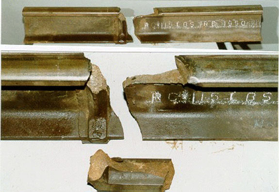
The rail east of the break had been rolled in 1950 and the one to the west, in 1979. Vertical wear and flange wear were within the acceptable limits set out in CN's SPC 3200 for 115-pound rail, namely 16 mm (5/8 inch) for vertical wear and 21 mm (13/16 inch) for combined vertical and flange wear.
Wheel flange marks were found on the turnout gauge plate and the tie plate 0.5 m west of the weld. There were no flange marks or scraping east of the broken weld. The broken thermite weld was located just beside a tie plate; the mould seam at the base of the weld was resting against the tie plate. The tie plate was attached to a wooden tie that was damaged and crushed.
The weld had been made with a straight base plate. There was a vertical mismatch of 6 mm between the welded rail ends. The date of the weld was not indicated, and there was no sign of a punch, tag or adhesive residue.
When train 783 went by, between the end of the crossing and the switch point for the industrial turnout, an abnormal impact coming from the side of the south rail was felt on board the lead locomotive. However, the crews of the two trains (305 and 131) that preceded train 783 did not feel any unusual impact.
1.15 Technical Examination of Rails and Truck
The sections of rail containing the broken thermite weld, six small fragments of rail and a broken truck side frame were sent to the TSB Engineering Laboratory for analysis. The six small fragments were found near the industrial turnout and the truck side frame was found among the debris. These had fractured under the impact of instantaneous excessive stresses sustained during the derailment.
On the welded pieces of rail, a fairly distinct smear mark measuring 115 mm in length was observed on the field side of the head of the west section. No wheel flange marks or scrape marks were found on the east section. Little damage from wheel pounding was seen on the fracture surfaces of the three pieces of the thermite weld.
A semi-circular dark area containing a pre-crack was located on the field side of the weld fracture surface, on the lower corner of the rail base (see Figure 5). It was 29 mm wide and 6 mm high and was located 22 mm from the weld axis. The pre-crack was located in the heat-affected zone of the weld, near a sudden change in the cross-section. The surface of the pre-crack was highly oxidized and showed no signs of recent growth.

The two surfaces of the pre-crack were cut out of the east and west rail sections. Analysis of these pieces with a scanning electron microscope and a metallurgical microscope confirmed that the pre-crack had begun in an area of acicular ferrite, a microstructure that has less resistance to fracture and impact, and that there was no recent extension of the pre-crack.
Charpy impact tests on rail specimens showed that the rail had an impact strength of 2 foot-pounds for the temperature prevailing at the time of the accident. This low value is consistent with the toughness of rail steels. Average tensile strength was 144 ksi;Footnote 5 yield strength was equal to 66 per cent of tensile strength, or 92 ksi.
On the west section of the rail, a vertical crack was found on the gauge side of the rail head. This crack, which originated in a manufacturing defect, had not spread to the running surface or web of the rail.
1.16 Track Welding
1.16.1 Continuous Welded Rails
On modern tracks, jointed rails have been replaced by CWRs to improve ride quality and reduce the costs of track maintenance and wear on rolling stock. CN defines CWR as any rail longer than 400 feet. The detailed procedure for installing CWR is outlined in SPC 3205.
The rails are first flash butt welded at the plant in lengths of up to 1 440 feet, and then laid and welded in the field by thermite or flash butt welding. In theory, CWRs can be infinite in length, but in practice, they are cut and bolted near any track features (such as bridges and switches). The rail is also cut and connected with insulated joints to allow for the operation of blocks (for rail traffic control) and signal systems for crossings.
Rail length varies with changes in temperature. In the case of jointed rails, these variations in length are accommodated by the expansion space left at the joints. In contrast, CWRs are designed to prevent expansion and contraction, generating stresses in the rail when the temperature varies from the temperature at which the rail was initially laid. In winter, for example, the rail is subject to tensile stresses and tends to break under certain conditions, especially if there is an internal defect in the metal.
Consequently, a preferred rail laying temperature (PRLT) for CWRs was established by the Engineering Department for each geographic area. In the Mont-Saint-Hilaire region, the PRLT is 80 degrees Fahrenheit (26.7 degrees Celsius). When CWRs are laid or adjusted at a temperature near the PRLT, thermal stresses are minimized. However, rails are subject to creep and longitudinal displacement under the combined effects of traffic and braking forces, or following maintenance work; therefore, the internal stresses may be redistributed. In other words, stress levels may change over time and may even become excessive in some places. The length of the rails must then be adjusted in the affected areas in order to reduce thermal stresses. This is known as rail destressing.
These phenomena are well known and are controlled by the railway companies through special measures included in construction standards and inspection and maintenance programs. Rail fracture is prevented primarily by identifying rail wear, detecting internal and external rail defects and limiting the dynamic stresses from wheels.
1.16.2 Welding Procedures
The two welding procedures used most often to assemble rails are flash butt welding and thermite welding.
Field welds are increasingly performed using an end-to-end flash butt welding process. This technique, routinely used for plant welds, has recently been developed for field welds and adapted for the North American market. In this procedure, the welding machine aligns the rails, presses them end to end and forges the ends together by charging the rails electrically. The upset material produced when the rails are pressed together is then sheared off and the head and base are ground. The weld geometry is checked (using a straight-edge and a taper gauge). The process also includes a magnetic particle inspection (MPI) of the weld. The quality of flash butt welding is more uniform and the rate of defects per weld is smaller than for thermite welds.Footnote 6
Thermite welding is a procedure that involves fusion casting. The welding system includes three main components: the crucible, where the aluminothermic reaction takes place, the charge that forms the filler metal, and the mould that surrounds the rail ends and gives the weld its shape. The casting process is preceded by preheating to reduce thermal stresses and allow a more homogeneous fusion of the base metal and the filler metal. Previously, the crucibles could be re-used up to 18 times; however, CN introduced one-use QP-CJ crucibles in 1995. The procedure for performing a thermite weld is described in CN's Track Welder Manual. A thermite weld requires 13 distinct steps that must be performed in a precise order by well-trained operators.
1.16.3 Rail Welding Requirements
The requirements for field welds are set out in SPC 1304 and SPC 3205.
In the SPCs in effect from 1981 to 1988, the following sections referred to welds:
- Thermite welds must not be located over ties, unless the base under side has been ground or sheared flush.
- Rails for butt welding, except for compromise welds, shall be matched to have the same vertical height and horizontal width. Mismatch must not exceed 1.5 mm.
- Plant welds must be inspected 360 degrees all round by MPI.
- Field welds must be inspected by R.U.M.P. (Railweld-Ultrasonic-Multiple Angle-Probe).
When the SPCs were revised in 1990, the following sections were added:
- For 136-pound rail, if this maximum (1.5 mm between two rail ends) is exceeded without reaching 8 mm, a compromise weld kit must be used.
- The Month, Year and Welder ID of each weld shall be identified by 13 mm characters on a tag on the field side of the web of the rail.
In the revisions of September 1996 and June 1997, the section on ultrasonic testing of field welds was removed, and the sections on flash butt welding, mismatch between rail ends and identification of welds were amended as follows:
- The height difference between two rail ends must not exceed 3.2 mm. If this maximum is exceeded without reaching 8 mm, a compromise weld kit must be used.
- The Month, Year and Welder ID of each weld shall be identified with a tag on the gauge side of the web—150 mm away from the weld.
- Plant or field butt welds must be inspected by MPI.
TC's Railway Track Safety Rules do not contain requirements on thermite welds. Railways are responsible for establishing standards on the installation and maintenance of CWRs.
1.16.4 Weld Execution
Track maintenance and repair is performed by local gangs and production gangs (district or division). Track inspection and routine maintenance that require few resources are carried out by local gangs while major work, such as tie or rail replacement programs requiring more extensive resources in terms of labour and heavy equipment, is performed by production gangs. Rail destressing and most field welds are done by production gangs. Local gangs may have one or two welders, whose primary responsibility is to weld frogs; however, these welders may sometimes make thermite welds.
The welders on local gangs receive the same training as production gang welders. A certified welder must take theoretical and practical courses for a total of three months over a period of three years. Upgrading sessions are offered regularly to supplement this training.
1.16.5 Date of Weld Execution
When a rail breaks, the local gangs immediately cut the broken section of rail and install a closure rail. Rail location, profile and type, ambient temperature, the length of the section laid and the difference between the length laid and the length removed are recorded on Form 1160, which is then entered in the rail fracture inventory. Once the rail is repaired, Form 1164 must be filled out and the database on CWR repairs and adjustments is updated. CN could not confirm the date of the weld nor did the database contain any information in this regard.
1.17 Detection of Internal Rail Defects
1.17.1 Ultrasonic Rail Testing
The first inspection cars were using magnetic induction. In this procedure, a magnetic field is created around the rail. Any defect or discontinuity in the metal cause distortion of the magnetic field which the system captures and analyzes. This procedure is still used for inspecting butt welds.
The ultrasonic testing technology chosen by CN uses the principle of sound reflection. The technology is based on the time it takes a sound wave to travel between the running surface and bottom of the rail and back. If a defect is found, the ultrasonic wave will be reflected or dispersed, making it possible to pinpoint the position and orientation of the defect through the intermediate echo that appears on the operator's display screen.
These systems are installed on Hi-rail vehicles to allow large-scale automated testing of the main tracks. The testing frequency varies from one region to another, depending on such factors as tonnage, traffic type and density, rail age and previous defect rate. Between Québec and Montréal, testing may be performed twice a year, but in western Canada, testing may be done six to eight times a year because of the higher tonnage and the number of unit trains. Since the introduction of 115-ton cars and new standards for rail wear, the frequency of rail testing has increased.
Because the majority of internal rail defects originate in the head and web of the rail, the system has a number of transducers that sweep the rail head from different angles. Defects in the base of the rail, on either side of the web, cannot be detected because they are outside the reflective field. According to the major rail testing companies, the existing technology can be adapted and used to inspect manually the rail base and welds that have not been ground. Manual testing involves use of a portable sensor or detection device and is a lengthy process because it must be done one weld at a time. A study published in 1975Footnote 7 gives a detailed description of the procedure for the manual inspection of thermite welds.
1.17.2 Field Weld Inspection
In the past, thermite welds done in the field by production gangs were manually inspected for internal defects with ultrasonic testing immediately after completion. However, the inspection was limited to the part of the weld that was ground, i.e., the rail head. In 1996, this procedure was discontinued on all classes of track, and inspection teams now perform visual inspections only and conduct Brinell hardness tests to ensure that the preheating and cooling procedures were done correctly. This practice is commonly used throughout the industry; however, Federal Railroad Administration (FRA) standards (Section 213.341) issued for high-speed tracks (passenger speeds in excess of 90 mph) require field welds to be inspected for internal defects at least one day and not more than 30 days after the welds have been made.
In 1996, CN concluded that ultrasonic testing had become superfluous and it was discontinued for the following reasons:
- the percentage of defective welds identified fell from 0.98 per cent in 1991 to just under 0.47 per cent in 1995;
- the quality of the materials used for thermite welding has improved;
- welding crews receive better training;
- inspection teams did not arrive until 10 to 14 days after completion of the welds; in many cases, the rail flaw detection car had already gone by.
Butt welds made in the field are still tested by MPI.
1.18 Rail Strength
1.18.1 Assessment of Residual Strength
Residual strength was analyzed using specialized fracture mechanics software. For a defect comparable in size to that found on the thermite weld (29 mm wide by 6 mm high), residual strength falls from 92 ksi to 30.13 ksi, or approximately 33 per cent of the initial yield strength.
The validity of the residual strength analysis was assessed by modifying certain input parameters and observing the effect of these modifications on the results. For example, by changing the Charpy impact strength from 2 to 4, residual strength increases to 34.95 ksi.
1.18.2 Assessment of Rail Stresses
Longitudinal stresses in the rail stem primarily from the following sources:
- static load—weight of cars (tare and loads);
- vertical dynamic load generated by wheel impacts;
- braking and accelerating forces;
- thermal stresses due to temperature variations; and
- residual stresses resulting from rail manufacture or welding.
Since train 783 was travelling at a constant speed, no braking or accelerating forces were present. Overall bending stress in the rail is obtained by adding the following stresses:
- bending stresses produced by the impact loadFootnote 8 exerted by the wheel;
- longitudinal thermal stresses caused by temperature variations; and
- residual stresses generated during manufacture of the weld.
Thermal stresses and residual stresses within a rail are generally very difficult to determine accurately. They are measured using stress relief methods that consist in first measuring a section of rail, cutting or drilling a hole in the rail, and then measuring the changes that occur. The internal stresses are relieved and disappear, but by measuring the changes, it is possible to obtain an indication of the original stress level. In the case of this rail failure, it is only possible to obtain a theoretical estimate of the stresses at the weld and in the immediate heat-affected zone (see Appendix A) since the rail failure "relieved" the stresses, making it impossible to measure them.
With respect to the base of the rail, wheel load and temperature create tensile stresses, the effect of which is neutralized by compression attributable to residual welding stresses. Under the effect of nominal static loads (33.5 kipsFootnote 9), temperature and residual welding stresses, the stress in the rail is lower than the rail's residual strength. However, since the stresses acting on the rail increase with impact load, the stress level in the rail becomes greater than its residual strength when wheel loads reach the following values:
- a wheel load of 100 kips if the residual strength of the rail is 30.13 ksi;
- a wheel load of 111 kips if the residual strength of the rail is 34.95 ksi.
1.19 Wheel Impact Load Detectors
1.19.1 Impact Levels
CN's procedures (see Appendix B) describe what action should be taken in response to the impact load measured by the WILD. CN's WILDs generate alarms when wheel impact loads reach thresholds of 100 kips, 125 kips and 140 kips. These thresholds are independent of local conditions.
When the impact load exceeds 140 kips, the car involved must be set off. If the train is heading towards a terminal, the car must be removed at the terminal, and if the train is leaving a terminal, the car must be removed at the first siding. In both cases, the wheels that set off the alarm must be replaced. Compliance with these procedures is flexible and responsive to operational factors. In 1999, for example, because of congestion in the yard at Jasper, Alberta, caused by an unusually high number of cars requiring repairs, the procedure was adapted to suit the operating conditions--only cars generating impact loads greater than 150 kips could be left in Jasper. Cars with impact loads between 140 kips and 150 kips were authorized to continue to the next terminal, either Edmonton, Alberta, or Kamloops or Prince George, British Columbia, without any speed reduction.
WILD alarm thresholds are continually evolving. Because of the complexity of the phenomenon and as CN's experience with the WILD system grows, the thresholds and procedures are continuously adjusted to minimize both the number of wheels detected and the number of in-service rail fractures.Footnote 10 When WILDs were introduced, the minimum threshold was 80 kips; in 1994, it was increased to 85 kips, then 90 kips and finally 100 kips. The maximum threshold was originally 150 kips; it was then reduced to 140 kips. In 1996, an internal CN statistical study designed to determine the correlation between rail breaks, train speed and temperature recommended decreasing the maximum to 125 kips and reducing train speeds when the temperature falls to minus 25 degrees Celsius.
It is recognized by the industry that wheels producing high impact loads may cause damage to equipment (axles and journals) and track infrastructure. CN's analysis of data collected between 1992 and 1995 clearly established a causal link between high impact loads and broken rails. Despite this link, CN does not reduce the speed of cars that have generated impact loads greater than 140 kips and does not require special inspection of the track in the section over which the defective wheel travelled, whereas other railways in Canada reduce train speed to 30 mph when the impact load exceeds 140 kips.
1.19.2 Communications
Unlike other wayside inspection systems, the WILD does not transmit information regarding wheel condition directly to train crews. After a train has passed over a WILD site, the field system processes the information, then transmits data by modem to a central office processor, located at the rail traffic control centre (RTCC) in Edmonton. Messages appear on the screen of the rail traffic control mechanical service representative (RTC Mech) and are printed out at the designated shop. Alarms for impact loads exceeding 140 kips are followed up by telephone with the RTC for the territory on which the train is travelling. When a train that has generated a WILD alarm does not go through the designated shop or is travelling away from it, a fax is relayed to a shop that can perform the inspections and take the appropriate corrective action; there is no mechanism to ensure that messages are received and corrective action is taken.
WILD communications are monitored on a computer screen in the office of the Signals and Communications Department technician located in Edmonton. When communication with a WILD site breaks down, the technician must try to re-establish communication. If communication cannot be re-established, a technician must be sent to the site to perform the necessary repairs. The technician responsible for WILD system monitoring in Edmonton is also responsible for maintaining the rail traffic control consoles, communication systems and WISs. The normal duties of the technicians keep them away from the WILD system maintenance screen sometimes for lengthy periods of time. There was no system in place to warn the technician that communication had been lost to any of the field WILD sites.
In the five days before the accident, communication with the Bagot WILD was lost several times. The communication system did not function between 1210 on December 26 and 1132 on December 28. During this period, 51 trains went by and 40 alarms indicating impact loads of more than 100 kips were generated, including 5 greater than 125 kips. On December 29 there were more communication breakdowns; between 1330 and 1533, 6 trains went through Bagot and the results of these readings were not received until 1709. One of these readings indicated that, at 1440, a train went by and generated impact loads of 146.3 kips. The train was travelling westward and should have been stopped at the Saint-Lambert Yard to set off the car with the defective wheel. Because of the delay in communication, the car was not set off until Coteau, Quebec. Communication was also interrupted on December 30 between 0634 and 1551. During this time, 17 trains went through Bagot; on 11 occasions, impact loads of more than 100 kips were recorded, including 2 of more than 125 kips.
1.20 Rail Breaks and Derailments
From 1995 to 1999, across the CN network, the number of rail breaks in service fell from 584 to 296,Footnote 11 a decrease of approximately 49 per cent. The number of rail breaks in the Halifax-Toronto corridor represents a small proportion of the total and was only slightly affected by this decrease (see Appendix C). For the same period, data from CN and all other railways in the country show that derailments and rate of derailments (derailments per million ton-miles) attributable to rail breaks followed the same downward trend. However, when all categories of derailment are taken into consideration, the absolute numbers fell by 21 per cent and the rate decreased by 16 per cent.
1.21 Emergency Response
The fire departments of most municipalities located along the Ultratrain route have intermunicipal mutual aid agreements to allow joint action in case of major disasters. All fire-fighters and officers must take the training required by the Regulation respecting the training of members of fire departments under the Quebec Fire Prevention Act. This theoretical and practical training includes response procedures for dangerous goods but does not include practical cases specific to rail transportation. The training is provided by agencies certified by the Quebec ministère de l'Éducation (Department of Education). The training of officers includes additional courses on surface transportation accidents.
The Mont-Saint-Hilaire public safety department was notified immediately after the accident. Given the size of the fire, the department put the City's emergency response plan into effect. Neighbouring municipalities that participate in the Montérégie intermunicipal mutual aid agreement immediately joined in. Fire-fighters from Mont-Saint-Hilaire asked the municipality of Beloeil for additional equipment. All fire departments equipped with heavy-duty monitor nozzles were then asked to participate.
In addition to members of the fire departments of 13 municipalities and staff of CN, Hydro-Québec and Gaz Métropolitan, representatives of various levels of government, the petroleum industry and clean-up companies arrived at the site at different intervals.
The first fire rescue vehicle arrived at the accident site at 1909; i.e., 10 minutes after the emergency call. While the fire-fighters were setting up their monitor nozzles and ladders, a tank car exploded (BLEVE). Half of the tank was thrown over the Benoît Road crossing, landing on the median strip of Highway 116. Everybody was ordered to move back. Hydro-Québec and Gaz Métropolitain took immediate action to isolate the power line and gas pipeline next to the railway. To ensure safety, the fire-fighters had to supervise all locations where work was being done. Since there were many ignition sources under the debris, the fire-fighters had to spray the debris at all times to cool it.
Because of smoke and risk of explosion, the residences bordering Laurier Boulevard and Benoît Road were evacuated. Residents of the Domaine des Hurons in Sainte-Madeleine were later evacuated to the Mont-Saint-Hilaire community centre. The evacuated residents were treated with respect and courtesy by the municipality of Mont-Saint-Hilaire.
Immediately after the accident, the public safety department asked CN for information on the dangerous goods carried by the two trains involved. The shipping documents were supplied by CN at 1933. The documentation regarding train 306 obtained at the accident site indicated that only a residue sodium chlorate car was involved in the accident. Train 306 was pulling some cars loaded with dangerous goods, but those cars were at the rear of the train and were not affected by the accident.
Throughout the response, regular coordination meetings were held with all involved participants. During these meetings, the participants discussed what action should be taken, and possible response methods and their impact on the progress of the clearing operations. To limit the spread of the fire, the fire-fighters asked CN to remove all the cars that had not derailed or overturned. All cars on the south track west of the derailment site were removed from the site. Some of these cars contained shredded paper that had caught fire.
At the 1000 meeting on December 31 the fire-fighters and the railway agreed to use foam in order to accelerate the process of putting out the fire and clearing the site and to use the foam truck from the Montréal International Airport (Dorval). The truck arrived at the site at 1345 on December 31. At about 1540, when the fire was thought to be under control, CN, the coroner's office and investigators from the Sûreté du Québec were authorized to begin their respective tasks. Shortly after, at 1647, the fire broke out again at the east end of the site. The Sûreté du Québec and the coroner stopped work and their staff withdrew to safety until the fire could be brought under control again. Operation of the foam truck was interrupted at about 1800 because there was no more foam available in the region. The next day, more foam was brought in from Ontario through the petroleum companies and fire-fighters from the municipality of Montréal East, which allowed the fire-fighters to resume work, using an additional foam truck supplied by Petro-Canada.
During the clean-up on 01 January 2000, after the fire had been under control, workers discovered a placarded hopper car that contained a dangerous good and had been punctured in the accident. CN took steps to identify the product and discovered that one of the cars, CGLX 483, had been loaded with sodium chlorate, despite shipping documents indicating that it was a residue. A portable decontamination unit was used to decontaminate everyone who had been exposed to the product.
1.22 Electronic Data Interchange (EDI)
Under the Transportation of Dangerous Goods Act and the Transportation of Dangerous Goods Regulations, a load of dangerous goods must be accompanied at all times by a shipping document that includes, among other things, information on the shipper, the consignee, the vehicle used, a description of the goods, and an identification of the placards and orange panels to be used during transportation. The documents accompanying the cars at all times may be printed copies of the original shipping documents or electronic copies generated at intermediary points using the electronic data interchange (EDI) system (a system used by CN to receive and exchange information on cars and their contents). Dangerous goods must also be accompanied by emergency response information. Some of the data contained in the shipping documents are appended to the train consist and used by the railway to describe the train consist and the position of the cars.
1.22.1 Sodium Chlorate Car
Car CGLX 483, which was the 12th car in train 306, regularly carries sodium chlorate from CXY Chemicals (CXY), an ISO 9002 certified manufacturer located in Beauharnois, Quebec, to Kimberly-Clark Inc. in Abercrombie, Nova Scotia.
On 15 December 1999, after being unloaded at Kimberly-Clark Inc., the car was sent back to CXY. The shipping documents accompanying the car indicated that it was loaded, when in fact it was empty. CN received the car at Truro, Nova Scotia, on December 16 at 1216. On December 21 it was transferred to the CSX Transportation, Inc. (CSX) railway at the Cecil Junction interchange point for delivery to CXY.
On December 24 the car was loaded with sodium chlorate by CXY. The content weighed 176 000 pounds. The shipping documents, dated December 28, were properly completed and indicated that the car was loaded for shipment to its destination in Abercrombie. A manual copy of the shipping documents was placed in one of the pigeonholes where the train crews usually collect them, and a copy was sent by fax to the CXY office in Vancouver, British Columbia, to be entered in the EDI system.
On December 28 the car was brought by a CSX train to Cecil Junction where it was picked up by CN train L53821-29. The car arrived at Coteau at 2115 to be added to train 306. As usual, the original shipping documents were left in a pigeonhole at the station.
On December 30 when train 306 from Toronto arrived in Coteau, it was taken over by a new crew. The train picked up several cars, including car CGLX 483. It left Coteau at 1544. The new crew had an electronic copy of the train consist for train 306 and electronic documents for the cars carrying dangerous goods obtained from the EDI system, in accordance with the Transportation of Dangerous Goods Act. The original documents, produced manually by CXY, were left in the pigeonhole. The information generated by e-mail indicated that car CGLX 483 was a residue car, having recently carried sodium chlorate.
1.22.2 Validation of EDI Corrections
The information sent by the CXY office in Beauharnois was not transferred to the EDI system by the Vancouver office. Therefore, the status of the car remained unchanged as a "load." However, in order for CN to add the car to train 306, once it was received from CSX, the CN office in Winnipeg updated the status of the car, and the new information was entered in the EDI system on December 29 at 1910, listing car CGLX 483 as empty. The next day, staff in Beauharnois discovered the error and at 0854 prepared a new electronic shipping document showing that the car was loaded.
To ensure safety and quality of data in the EDI system, significant changes to the shipping documents (such as a car that is loaded rather than empty) are not performed automatically, but must be validated by CN. The amended shipping document remains "suspended" in the EDI system and the new data are not validated until a CN employee acknowledges receipt of the transmission. When train 306 left Coteau on December 30 the transmission sent by CXY had not yet been validated. Consequently, the corrections made by CXY did not appear in the documents generated by the EDI system. Therefore, when the crew members of train 306 left Coteau, the documents that they had in their possession indicated that the 12th car behind the locomotives contained sodium chlorate residue, rather than being loaded.
There is no mechanism to eliminate mistakes at the source nor are there procedures to warn CN that documents are suspended (such as telephone or electronic mail) or to check train cars against the information on the shipping documents. The railways used to have weigh scales in the local yards, where most cars could be weighed before being added to a train. The cars could then travel to the main yards, such as the Taschereau Yard in Montréal, where they would likely be weighed again during humping operations. Since CN has rationalized its humping activities and modified its operating methods, cars are weighed by the shipper and there is no longer any verification of car weight en route. However, the railways, in cooperation with the WILD suppliers, are conducting research to adapt the WILD for in-track weighing.
1.23 Event Recorders
The event recorders on the two locomotives of train 306 were sent to the manufacturer, and then analyzed by the TSB Engineering Laboratory. The data could not be recovered because the recorders had been damaged by fire and heat. The electronic cards and cabling in the recorder of the lead locomotive were completely destroyed and the electrical connections had melted. The recorder was subjected to temperatures of at least 1 080 degrees Celsius. The power supply batteries in the event recorder from the second locomotive were destroyed, resulting in loss of its data. The cases of the two recorders were made of 3.5 mm carbon steel, which has little resistance to heat and impact.
Following a collision on 15 February 1986 at Mile 13.8 of the Drummondville Subdivision, the Canadian Transport Commission ordered federally regulated railways to install event recorders in locomotives operated on main tracks. The purpose of the recorders was to collect information that would help to clarify the causes and factors contributing to accidents and to prevent the recurrence of such accidents. Order R-40339 of 19 February 1987, in particular, outlined the information that the recorders should be able to capture: time, speed, distance, brake pipe pressure, throttle position, emergency brake application, independent brake cylinder pressure, pressure and use of the locomotive whistle. The order did not establish any design or resistance criteria.
Current regulations have not amended those requirements. There are still no design or performance standards for locomotive event recorders. In contrast, the standards for the aeronautical and marine modes of transportation include manufacturing and performance criteria for extreme conditions (fire, impact, immersion). For example, these standards require a fire resistance of 60 minutes at 1 100 degrees Celsius and 10 hours at 260 degrees Celsius; the recorder must also be able to keep its data even if power is lost (non-volatile memory).
Between 1990 and 1999, the TSB conducted investigations into four major accidents in which crew members were fatally injured. In three of these accidents, the data in the event recorders were lost because the recorders had been exposed to impact, fire or contamination by water.
- In July 1992, a subgrade failure at Mile 135.0 of CN's Caramat Subdivision near Nakina, Ontario, led to the derailment of a CN train. The four locomotives fell into a lake and sank. Two of the three crew members were killed and the third sustained serious injuries. The event recorders were recovered, but the data they contained were lost when the power was cut off after water contaminated the storage batteries and memory circuits (TSB report No. R92T0183).
- In August 1996, near Edson, Alberta, a CN train collided head-on with a cut of 20 runaway cars. The three people located in the cab of the lead locomotive of the freight train were fatally injured. The event recorder from the first locomotive was destroyed in the collision and the ensuing fire. The event recorders from the second and third locomotives were recovered and the data were downloaded (TSB report No. R96C0172).
- In March 1997, as a result of a large roadbed depression at Mile 106.15 of the Ashcroft Subdivision near Conrad, British Columbia, a CN train travelling towards Kamloops, British Columbia, derailed. Both crew members were fatally injured. The data from the event recorder could not be recovered because the locomotives were destroyed by fire (TSB report No. R97V0063).
1.24 Safety Regulations
TC's mission is to develop and administer policies, regulations and services for the best possible transportation system for Canada and Canadians: one that is safe, effective, affordable, integrated and environmentally friendly. TC's role consists in establishing modern, relevant legislation and policies and ensuring that the highest possible level of safety is maintained. The Safety and Security Group is responsible, through the Rail Safety Directorate and the Transport Dangerous Goods Directorate, for developing and enforcing regulations on railway safety and public safety with respect to the transportation of dangerous goods.
The directorates and the five regional offices, in Vancouver, Winnipeg, Toronto, Montréal and Moncton, are responsible for applying TC's programs, policies and standards.
1.24.1 Railway Safety
TC's Rail Safety Directorate administers the Railway Safety Act and enforces its provisions. The following are fundamental principles on which the regulation of rail safety in Canada is based:
- railways are responsible for the safety of operations; and
- the regulator must have the power to protect public and employee safety.
TC achieves this role either by regulating in accordance with government regulatory policy, or by approving rules developed in consultation with relevant associations and submitted by the industry.
In the exercise of its responsibilities with respect to regulatory overview, TC has instituted a series of policies governing monitoring of such components of the railway system as infrastructure, rolling stock and train operations. Records are kept on inspections, defects identified and the corrective action taken.
TC inspectors perform safety inspections. They review and audit the records of the railway's own compliance monitoring program, and then examine the end result by inspections and site monitoring, to focus on safety systems and patterns of compliance and to determine systemic safety problems. In order to ensure that safety audits are reliable, infrastructure and rolling stock inspectors use a sampling method to determine a statistically significant number of elements to inspect. The audit is completed by checking existing procedures and records.
1.24.1.1 Infrastructure Programs
Infrastructure inspectors choose samples from the following five data sources:
- logbooks;
- rail defect data;
- track geometry car data;
- turnout condition data; and
- bridge and culvert condition data.
Sample sizes are based on the extent of trackage in each region, risk assessment, and historical data on the subdivisions. The distribution of samples is biased towards track classes presenting higher risks. For example, high-speed main tracks will receive more attention than secondary tracks.
For the Quebec region, sampling over at least 1 300 miles of track must be completed to obtain a minimum confidence level of 95 per cent. (This means that the probability is 0.95 that the condition of track assessed from the sample actually reflects the condition of the entire trackage.) In 1999, TC's regional infrastructure inspector inspected approximately 2 500 miles of track.
The Saint-Hyacinthe Subdivision was inspected by TC on 02 December 1999, between Mile 38.7 and Mile 68.5. Defects in the planking of the crossings, loose switch rod connectors and a low bridge approach were reported to CN and have been corrected.
1.24.1.2 Rolling Stock Programs
Rolling stock audit programs are used to inspect railway equipment (locomotives and cars) and include other programs more specifically related to tests and procedures used by the railway companies (such as brake tests and flag protection).
Three types of safety audits are performed under the rolling stock programs:
- comprehensive audits--during these audits, both rolling stock and existing standards and procedures are thoroughly examined;
- follow-up audits—these supplement the comprehensive audit and allow follow-up;
- special audits—these involve in-depth examination and analysis of specific problems.
Each station must be the subject of one complete comprehensive audit a year; the number of follow-up audits depends on previous results, accident and incident trends and employee performance.
TC conducted four safety audits of the Joffre Yard over a 16-month period, from June 1998 to October 1999. A total of 274 Ultratrain cars were inspected; 7 exceptions to the FCSR were found and corrected immediately by the railway.
1.24.1.3 Wheel Impact Load Detectors
Installation of WILDs was an industry initiative. There was limited participation or consultation between TC and the railways with respect to the development of these systems, alarm thresholds or response procedures. TC has no regulations, standards or inspection programs relating to these systems.
1.24.2 Transportation of Dangerous Goods
The transportation of dangerous goods by air, marine, rail and road is regulated by the Transport Dangerous Goods Directorate under the 1992 Transportation of Dangerous Goods Act. The Transportation of Dangerous Goods Regulations, adopted by all provinces and territories, establish the safety requirements for the transportation of dangerous goods.
1.24.2.1 Inspection Program
TC's Compliance and Response Branch, with the assistance of the five regional offices, ensures that consignors, carriers and consignees are complying with the Transportation of Dangerous Goods Regulations through a national inspection, investigation and enforcement program.
The qualitative criteria for the monitoring program of the transportation of dangerous goods are clearly defined in the Inspector's Manual. The schedule of inspections is based on three levels of priority (1, 2 and 3). The involved parties are classified according to their role and importance in the handling and transportation of dangerous goods. TC's strategy consists in inspecting dangerous goods before they enter the transportation system; therefore, inspectors focus on "Priority 1" parties, which include, among others, the manufacturers.
The program's quantitative parameters, such as inspection frequency and percentage of parties inspected annually, are not specified in the Inspector's Manual, but the objective is to inspect "Priority 1" parties every six years.
TC inspectors visited CXY on 24 February 1999. The general compliance report indicates that a rail shipping document was checked and that no non-compliance with the Transportation of Dangerous Goods Regulations was found. The general compliance report does not indicate that the accuracy of the shipping document was checked nor that it was compared against car weight and content. TC's inspection records do not mention any inspection of the procedures for transferring documents at Coteau.
1.24.2.2 Emergency Response Plans
Emergency response plans are used to define roles, resources and priorities in advance. They are based on projections made through risk analysis. They help to ensure that specialized equipment and resources are available when needed.
Shippers and importers of dangerous goods listed in Schedule IFootnote 12 of the Transportation of Dangerous Goods Regulations, as well as carriers who transport these products more than 70 km across Canada, must have emergency response plans approved by the Minister of Transport. These requirements apply when the quantities involved exceed certain limits based on product toxicity and reactivity. For example, a shipper or importer of propane (UN 1075) or solid phenol (UN 1671) would need an approved emergency response plan to handle net quantities of more than 3 000 kg or 3 000 L.
According to TC's document TP 9285 (Emergency Response Assistance Planning), every plan should include a stated policy, purpose and organizational structure, geographic scope, and list of commodities posing a risk. TP 9285 describes the areas that must be included in all emergency plans, namely:
- activation (internal alerting, authority);
- response tasks (external alerting, emergency response methods);
- resources (equipment, personnel); and
- preparedness (risk assessment, training, maintenance).
The document states, among other things, that the emergency response methods to be used for each type of dangerous good as well as the necessary resources and equipment should be specified in the emergency response plan.
Although rail carriers are required to have emergency response plans only in cases where dangerous goods transit through Canada, CN has an emergency response plan (TP 110L [ERP2-0120]), which was submitted to TC's Transport Dangerous Goods Directorate. The June 1999 version of the plan did not follow the model given in TC's document TP 9285; such elements as response methods, resources and preparedness were not included. The plan dealt almost exclusively with internal and external alerting, i.e., the people and organizations to be contacted in case of an accident involving dangerous goods as prescribed by Section 18 (Duty to respond) of the Transportation of Dangerous Goods Act.
Neither CN nor Ultramar are required to establish specific emergency response plans for the Ultratrain since the hydrocarbons it carries are not listed in Schedule I.
2.0 Analysis
2.1 Introduction
The radio transmission heard in the locomotive of train 783 just before the accident, to the effect that cars from train 783 were fouling the south track, the position and angle of the locomotives of train 306 after the collision and the broken south rail of the north track clearly indicate that cars from train 783 derailed, fouling the south track, and were struck by train 306. The analysis will focus on the causes and factors that contributed to the derailment of train 783.
Before the location where the south rail of the north track broke, no marks were found on the track or roadbed indicating that a wheel had climbed the rail or that an equipment failure, such as a broken wheel or axle, had caused the derailment. The equipment on the cars of train 783 was examined and no irregularities that could have contributed to the accident were observed. In addition, no defects were detected by the WISs closest to the accident site. Since the train operation was consistent with company procedures and government safety standards, this analysis will concentrate primarily on the fractured thermite weld, related weld maintenance and inspection practices, wheel impact load detectors and emergency response.
2.2 Fractured Thermite Weld
The south rail of the north track broke at a thermite weld. No wheel flange marks or scrape marks were found east of the broken weld; consequently, it may be concluded that the derailment did not occur to the east of the weld. The shape of the first scrape observed on the field side of the rail head, immediately west of the weld, indicates that the wheel flange climbed the rail at that point; this is also consistent with the wheel flange marks seen on the turnout gauge plate and the tie plate west of the weld.
The chevron markings observed on the fracture surfaces are consistent with a rapid overstress fracture. The direction of these markings indicates that the break originated in the pre-crack area located in the lower corner of the rail base. Once initiated, the fracture occurred quickly, with the head of the rail breaking last. The pre-crack showed no signs of recent growth. It lacked the black colouration, which is usually associated with oxidation at high temperature, indicating that it formed after the weld was made, probably as a result of residual stresses created during welding. The thickness of the oxide layer indicates that the pre-crack was at least nine months old.
Fracture mechanics calculations based on the results of Charpy impact tests and tensile tests showed that, at the ambient temperature at the time of the accident, the pre-crack had actually reduced the rail's strength to approximately 33 per cent of the initial yield strength. Mismatch between the rail ends and use of a straight base plateFootnote 13 created a notch effect conducive to the development and propagation of cracks. A sloped base plate would have allowed a more gradual transition between the two rails, lessening this effect.
Since little damage from wheel pounding was observed on the fracture surfaces of the weld, it can be concluded that the fracture was very recent and that the head section of the thermite weld separated shortly before the derailment. In all probability, the 15th car derailed when the rail head section separated. The wheels of the car fell onto the roadbed on the south side. The derailed cars then fouled the adjacent track, where they were struck by train 306. The two crew members on train 306 were fatally injured in the deflagration that occurred when the lead locomotive struck the 15th car of train 783.
Stresses generated by wheel loads, thermal stresses caused by the drop in temperature and residual welding stresses were present at the point of fracture. According to the analysis of these stresses, for the temperature at the time of the accident, the stress in the rail reaches the rail's residual strength and would be theoretically sufficient to break the weld at the existing pre-crack when the impact load exceeds 100 000 pounds. This load increases to 111 000 pounds when the toughness value is doubled. Such impact loads are common; in fact, the day of the accident, at 1540, the Bagot WILD detected a car with an impact load of 103 000 pounds.
The impact load needed to break the weld may have been even lower than calculated, since the mould seam of the weld was resting against the tie plate, which may increase the stress in the rail. Recent resurfacing of the western approach to the crossing may have had an effect on the redistribution of stresses in the rail and led to a localized increase in thermal stresses. Even taking a conservative approach, by allowing for variations in rail toughness and ignoring the increase in stress caused by the position of the weld and the resurfacing, it may be concluded that the existing pre-crack was sufficient to cause the rail break under the effect of the stresses caused by the low temperatures and wheel impact loads lower than the WILD limits set by CN for car set-off.
The impact loads exerted by the wheels and the cold temperatures may also have played a role in causing the vertical crack observed on the gauge side of the west part of the rail head. However, this crack, which did not propagate into the surface or web of the rail, is not considered to have contributed to the accident.
2.3 Field Welds
2.3.1 Testing
Although TC's Railway Track Safety Rules did not require any testing for internal defects in thermite welds, CN was performing manual ultrasonic testing on the ground surface of the weld. This inspection, as performed, allowed detection of defects in the head and web of the rail but would not have detected the pre-crack in the base. Although not comprehensive, this inspection nevertheless represented an essential safety tool, especially on tracks where inspection frequency is low, such as the main tracks in eastern Canada. CN could easily have adapted the same technology to the unground portion of the weld to identify defects in any part of the rail periphery, but like the other railways, CN instead discontinued ultrasonic inspection of thermite welds. Inspection of flash butt welds is still required, even though their quality is more uniform and their rate of defects is lower.
According to CN, thermite field weld inspections became redundant because, between 1991 and 1995, the rate of defects in thermite welds had decreased by half. CN's decision to discontinue manual ultrasonic inspection was applied to all subdivisions, regardless of local conditions, tonnage, speed or traffic type and density. The new FRA standards have recognized the influence of these factors and require field welds on high-speed tracks to be inspected for internal defects. The rate of weld defects may have declined, but residual risks exist and may be considered high on some sections of track. The inherent characteristics of the main tracks used by passenger trains or by trains carrying large quantities of dangerous goods in urban areas should be taken into consideration. It is true that considerable progress has been made in the area of thermite welding; for example, the introduction of single-use crucibles has reduced the risk of porosity. However, the large number of steps involved in a thermite weld and the critical nature of certain steps, particularly the preparation and alignment of the rails and the preheating phase, remain weaknesses and may still lead to mistakes.
The section of track involved had last been inspected by the rail flaw detection car about two months before the derailment and no internal rail defects had been found. In any case, the pre-crack could not have been detected by automatic inspection methods because it was located in the base of the rail. The probability of detecting cracks at the time they emerge in the web of the rail is still relatively minimal because, once started, this type of crack propagates rapidly. Without an ultrasonic inspection of the entire periphery of the weld, defects in the base cannot be detected and may cause rail failure, jeopardizing the health, safety and welfare of employees and people living near railway tracks.
2.3.2 Quality Assurance
CN's quality assurance system did not detect the fact that the weld did not meet the company's standards. Moreover, the weld was not entered in the inventory of CWR repairs and adjustments. The investigation did not reveal whether this was a common practice because only a visual inspection of a large enough random sample of existing welds could give an accurate estimate of the potential risks. Since defects are more likely to go undetected when there is no quality control, it is likely that the fractured weld was done by a local gang, because only welds made by production gangs are controlled by independent inspections. However, since welders on local gangs receive the same training as welders on production gangs and local gangs seldom make field welds, it may be concluded that the number of welds that do not comply with CN's requirements should be relatively small. Nevertheless, since welds are critical elements of track infrastructure, quality control by independent personnel is imperative for immediate identification and rectification of dangerous conditions or inadequate work methods.
The fact that the mould seam of the weld was resting against the tie plate may have increased impact loads. However, it is unlikely that the mould seam was in that position when the weld was made, because it would have been impossible to properly position the mould that way. The weld must have been displaced under the effect of rail creep attributable to thermal and dynamic stresses. Despite bi-weekly visual track inspections, the position of the mould seam was not observed and corrected. In fact, these routine inspections are sufficient for checking changes in track condition, but not for detecting specific details, which are quite difficult to see from a Hi-rail vehicle travelling at a speed of up to approximately 20 mph. This is understandable from the standpoint of human factors and many cognitive psychology researchers, such as G. Miller (1956),Footnote 14 D. Lane (1982),Footnote 15 or C. Wickens (1984),Footnote 16 have described in detail the capacity limits of human information processing. Inspectors must perform a large number of separate but concurrent visual inspection tasks (track geometry, rails, ties, ballast, drainage, turnouts, crossings, signal equipment, fencing). When people are required to do more than one task at the same time, performance on at least one of the tasks declines. People can keep track of between five and nine items of information at one time. However, if a number of concurrent tasks make use of only one sense, like vision, in the case of track inspectors, then this number is further reduced. Consequently, only specific inspection of the weld and measurement of the mismatch between the rail ends would have shown that the weld did not meet the existing standards and that it was resting against the tie plate.
2.4 Rail Breaks and Derailments
From 1995 to 1999, across CN's network, the number of rail breaks in service fell from 584 to 296, a decrease of about 49 per cent. For the same period, the rate of derailments due to broken rails followed the same downward trend, not only in CN's network but throughout the industry. Increased use of WILDs and more frequent testing for internal rail defects probably contributed to the overall decline in in-service rail breaks and related derailments.
However, it should be noted that CN's rate of derailments (in all categories) has always been lower than that of the industry as a whole (less than 78 per cent) while the company's rate of derailments due to rail breaks is close to the industry average, even equalling it in 1996 and exceeding it in 1998. Unlike the other railways in Canada, CN does not reduce train speed when wheel impact load is greater than 140 kips. This difference in procedure may contribute to but is insufficient alone to explain this discrepancy. Factors such as the age, profile and metallurgy of the rail, tonnage, geometry, and each company's inspection and maintenance standards must be examined to establish their contribution.
When train 783 entered the block where the rail broke, the block signal was displaying a clear signal indication; however, between the crossing and the switch for the industrial track, an unusual impact coming from the side of the south rail was felt on board the lead locomotive. In all probability, the rail had already broken but the flow of electrical current had not been disrupted because the rail head had not yet separated. The fact that the signal system was still working is not considered a flaw since the signal system's primary function is to control train movements, not to detect rail breaks. However, the system's ability to detect rail breaks is used by the railway companies and explains in part why CN does not require any special track inspection or reduction in train speed when the WILD detects impact loads of more than 140 kips.
It is true that only a tiny percentage of rail breaks lead to derailments. In 1999, across CN's system, there were 296 rail breaks and only 4 related derailments. This suggests that the signal system is sufficient as a secondary safety measure; however, it is not always reliable and should not be used as the primary safety measure since a rail could break directly under a train. Furthermore, some subdivisions do not have signal systems or, as in the Saint-Hyacinthe Subdivision, trains may be authorized to travel in the opposite direction to the signals; therefore, they no longer would have a warning system. In relying on the signal system's ability to detect rail breaks, railway companies are exposing their employees and the public to increased risks. Therefore, programs to identify rail wear and internal defects and control impact loads are paramount in significantly reducing rail breaks and, consequently, the risk of derailment.
2.5 Wheel Impact Load Detectors
Although the industry recognizes that wheels generating high impact loads may damage railway equipment and infrastructure, and although CN has clearly established a causal link between high impact loads and rail breaks, there are still no standards or regulations in this regard. Analysis of the historical development of alarm thresholds shows that these levels are established on an empirical basis and are often changed because of operational requirements. The maximum impact level for which CN requires a car to be set off used to be 150 kips. This was then reduced to 140 kips. The Association of American Railroads (AAR) accepts 90 kips as a replacement criterion for out-of-round wheels but does not specify an impact limit for wheel surface defects. Some railway companies take no action when the impact level is 140 kips while others reduce train speed to 30 mph. Moreover, the existing procedures are relaxed when dictated by local conditions, as was the case in Jasper in 1999. Consequently, CN's procedures for wheels that generate impact loads of more than 140 kips are not always followed, and some cars with defective wheels that could damage the track are allowed to remain in service over long distances without restriction.
However, it must be recognized that impact load is only one of numerous variables that contribute to rail failure and that it is very difficult to predict its influence reliably. Many variables come into play and their interaction is still poorly understood: rail characteristics, temperature, temperature gradient, track rigidity. It is difficult to include all the variables and establish minimum values that would take both safety criteria and operating criteria into account; however, given the importance of impact loads on rail failures, a rigorous approach is essential to reducing accidents caused by rail and wheel failures.
Communication between the WILD and the RTCC in Edmonton is overseen by the RTCC technician in Edmonton using a computer screen placed on his/her desk. Since the technician has many other duties and seldom sits at his/her desk, he/she cannot detect communication breakdowns in a timely manner. The design of the technician's office was such that, given responsibilities that required him/her to be elsewhere, he/she was not likely to notice a loss of communication.
When transmission of readings by the Bagot WILD was interrupted in the days before the accident, the breakdown lasted for several hours. Essential safety information was not conveyed and a car with an impact load greater than 140 kips continued to travel another 41 miles (to Coteau) before it was set off. Since the WILD communication system is not fail-safe, a communication breakdown may hamper its operation and allow defective wheels to continue in service at the risk of breaking or breaking a rail.
Unlike the other wayside systems, the WILD does not transmit any information to train crews, but communicates it to personnel located miles away. This system depends on reliable communications, operating printers and faultless human interaction to allow the necessary corrective action to be taken immediately when a wheel that exceeds safety limits is detected.
TC has traditionally had rolling stock and track inspection programs but has not yet established a program for monitoring the new systems introduced by the railway companies in recent years, such as the WILDs. Just like wheel inspection and track testing, impact load monitoring is essential to a reduction in rail breaks and equipment damage. Railways are responsible for the safety of routine railway activities, but in the public interest, TC must ensure, through its regulatory supervision, that railways have adequate tools and systems to ensure safe rail operations.
2.6 Event Recorders
The TSB has succeeded in recovering data for the vast majority of railway accidents it has investigated; however, in the case of most major accidents, the data were lost. The existing regulations contain no requirements for the design and construction of locomotive event recorders; consequently, the recorders in use have little resistance to impact and fire and are generally equipped with a volatile memory. In this accident, the locomotives were subjected to extreme conditions: in the case of the lead locomotive, the temperatures and the length of time for which the recorder was exposed exceeded the standards established for the other modes of transportation. The recorder in the second locomotive was less severely damaged and the data could have been recovered if the recorder had been equipped with non-volatile memory or if it had been designed and manufactured according to the standards for other modes of transportation. It must be concluded that the absence of design and construction standards for the locomotive event recorders impedes efforts to understand rail accidents and improve the safety of this mode of transportation.
2.7 EDI and Train Consist
Since the sodium chlorate did not come into contact with the hydrocarbons, the mistake in the shipping documents did not have disastrous consequences. However, the investigation revealed weaknesses in the existing procedures and identified hazards and dangerous conditions to which emergency response personnel and the general public may be exposed.
The validation procedures used by CN delay real-time transfer of information without eliminating the risk of mistakes. To ensure safety and quality of the data in the EDI system, it is understandable that amendments to shipping documents be validated by CN; however, since these documents are used by the train crews, the amendments should be made in real time to give those crews access to the correct information. CN's procedures do not meet this objective since there is no audible or visual mechanism to warn the CN staff responsible for validating the data when information has been "suspended" in the EDI system. This may delay updates and leave erroneous data in the system.
Although the EDI system does not automatically amend documents and "suspends" any new data, it continues to use the old information, even when it is erroneous. Since the EDI software is not fail-safe, erroneous information is not frozen when new data are "suspended." Consequently, the system continued to generate inaccurate train consists even though the correct information had been entered, specifically indicating that car CGLX 483 was loaded with sodium chlorate.
Documentation errors were made in different places by three different companies (Kimberly-Clark Inc., the CXY office in Vancouver and the CN office in Winnipeg ); however, this does not necessarily indicate a systemic weakness as the errors may have been related. Nevertheless, the system is vulnerable since it receives data from a large number of users. Even the most motivated employees are fallible and may make mistakes. The existing system has no protection against normal human error, as is demonstrated in the case of CXY even though the company had a certified quality assurance program. The investigation also revealed that there are no procedures for verifying and physically comparing shipping documents against the train consist. Since weighing of cars is left to the shippers' discretion, and CN no longer re-weighs cars at the yards, an incorrect weight entered by a client may go unnoticed. Until the WILDs are calibrated for in-track weighing of cars, this failure to check car weight at any point increases the risk for employees and the public. Gross errors (an empty car instead of a loaded car) affect the train consist and may create dangerous conditions in terms of train operation and emergency response, but overloaded cars can affect the safety and integrity of the infrastructure, particularly on secondary lines and on short-line railways where the capacity of the infrastructure (track and bridges) might be marginal.
TC inspectors visited the shipper 10 months before the accident; however, even if their inspection had taken place on the day the mistake was introduced, it would probably not have been detected, since it was made in Vancouver. Only a comparison between the shipping documents generated by the EDI and the car's loading would have revealed the mistake; however, TC's inspection documents have no record of such a comparison. Furthermore, because there was no inspection at the Coteau interchange point, there was no way to ensure that the documents were sent to all involved parties. In this context, the supervision exercised by TC is insufficient since it does not detect this type of non-compliance. In addition, since not all involved in the transportation of dangerous goods have adequate quality assurance systems, the inspection frequency recommended by TC—once every six years at best—is not conducive to ensuring that the transportation and handling of dangerous goods are always consistent with the Transportation of Dangerous Goods Regulations.
2.8 Ultratrain Tank Cars
This accident involved a derailment, followed by a collision. The tank cars directly involved did not withstand the force of the impact and explosions. Given the extent of the accident and the forces involved, this is an extreme case that does not provide any information or reveal any weaknesses in the design and construction of the rolling stock.
2.9 Emergency Response
Appropriate and effective measures were taken to protect the site and ensure public safety. The evacuation by the municipality of Mont-Saint-Hilaire was conducted in an exemplary manner.
The inter-municipal mutual aid agreement worked well, and adequate human resources and standard equipment were available. However, the pile-up of cars made the fire-fighters' job extremely difficult because the fire was hidden under the debris. Even when no source of ignition was visible and the fire seemed to be under control, it broke out again. This led to some problems in protecting the site, but at no time was the safety of those fighting the fire compromised. Overall, the fire-fighters performed their role in an effective manner, even though they were facing a major disaster involving a mode of transportation not covered by their practical training.
According to the Transportation of Dangerous Goods Regulations, neither CN nor Ultramar are required to establish specific emergency response plans for the Ultratrain because the hydrocarbons carried by this train are not listed in Schedule I. Nevertheless, CN had a plan known as ERP2-0120. This plan did not follow TC's document TP 9285 and could not, in any case, meet the specific requirements of the Ultratrain since it did not define any roles, resources and priorities for emergency response ahead of time. This was clearly demonstrated at the site: the decision to use foam and certain other logistical matters had to be discussed during the operation, hindering the fire-fighting efforts. An emergency response plan based on TC's document TP 9285 would have facilitated and accelerated the fire-fighting efforts by defining roles ahead of time, establishing appropriate response methods and providing an inventory of the foam and equipment available in the region.
There is no doubt that the requirements and the products included in Schedule I were based on a risk assessment that took into account the physical and chemical properties of the various substances, the amounts involved and the environment through which these products are transported (urban areas). However, without challenging this analysis, it should be noted that the introduction of unit trains carrying liquid hydrocarbons in urban areas creates unusual operating conditions that reveal certain weaknesses of Schedule I; for example, an emergency response plan is required to ship or import 3 000 kg of solid phenol (UN 1671), which is clearly toxic, but remains contained in the car rather than spilling in case of derailment, but no such plan is required to handle 6.5 million litres of gasoline, as in the case of the Ultratrain. Without an emergency response plan, it is difficult to ensure immediate implementation of the appropriate action in the event of an accident involving dangerous goods and that the response is adapted to the risk.
The accident occurred less than 25 miles (40 km) from downtown Montréal in a sparsely populated area, but the Ultratrain's route takes it through many urban areas where the risk is much greater. Leaks or spills of dangerous goods may jeopardize the health, safety and welfare of employees and residents living near railway tracks, but the risk is even greater in the case of tracks running through urban areas. The existing safety regulations already take these factors into consideration for products included in Schedule I. It is essential that a similar approach be adopted for dangerous goods transported in large quantities, and that the risk be re-assessed.
The contamination was more concentrated in the area where the cars piled up and in the ditches where the hydrocarbons spilled. Since the contaminated soil of the railway roadbed, the highway and the ditches was dug up and removed for treatment, the long-term environmental impact was minimal.
3.0 Findings
3.1 Findings as to Causes and Contributing Factors
- The two crew members on train 306 were fatally injured in the deflagration that occurred when the lead locomotive struck the 15th car of train 783.
- In all probability, the 15th car of train 783 derailed when the rail head section separated.
- The direction of the chevron markings observed on the fracture surfaces indicates that the break originated in the pre-crack area located in the lower corner of the rail base.
- The mould seam of the weld resting against the tie plate, the mismatch between the rail ends and the use of a straight base plate created conditions conducive to the development and propagation of cracks.
- The existing pre-crack was sufficient to cause the rail break under the effect of the stresses caused by the low temperatures and wheel impact loads lower than the wheel impact load detector (WILD) limits set by Canadian National (CN) for car set-off.
- Only specific inspection of the weld and measurement of the mismatch between the rail ends would have shown that the weld did not meet the existing standards and that it was resting against the tie plate.
3.2 Findings as to Risk
- Like the other railway companies, CN discontinued ultrasonic inspection of thermite welds. Inspection of flash butt welds is still required, even though their quality is more uniform and their rate of defects is lower.
- Manual ultrasonic testing, as practised by CN, would not have detected the pre-crack in the base, but nevertheless represented an essential safety tool, especially on tracks where rail flaw inspection frequency is low.
- Without an ultrasonic inspection of the entire periphery of the weld, defects in the base cannot be detected and may cause rail failure.
- Since welds are critical elements of track infrastructure, quality control by independent personnel is imperative for immediate identification and rectification of dangerous conditions or inadequate work methods.
- Although the industry recognizes that wheels generating high impact loads may damage railway equipment and infrastructure, and although CN has clearly established a causal link between high impact loads and rail breaks, there are still no standards or regulations in this regard.
- Since the WILD communication system is not fail-safe, a communication breakdown may hamper its operation and allow defective wheels to continue in service at the risk of breaking a rail or damaging equipment.
- Since weighing of cars is left to the shippers' discretion and CN no longer checks car weight, an incorrect weight entered by a client may go unnoticed, increasing the risk to employees and the public.
- Because the electronic data interchange (EDI) software does not freeze erroneous information when new data are "suspended," the system can continue to generate inaccurate train consists even though the correct information is available.
- The inspection frequency recommended by Transport Canada (TC)—once every six years—is not conducive to ensuring that the transportation and handling of dangerous goods are always consistent with the Transportation of Dangerous Goods Regulations.
- An emergency response plan based on TC's document TP 9285 would have facilitated and accelerated the response by defining roles, establishing appropriate response methods and providing an inventory of the foam and equipment available in the region.
- The transportation of large quantities of liquid hydrocarbons on unit trains through urban areas creates a risk.
3.3 Other Findings
- Increased use of WILDs and more frequent testing for internal rail defects probably contributed to the overall decline in in-service rail breaks and related derailments.
- The absence of design and construction standards for the locomotive event recorders impedes efforts to understand rail accidents and improve the safety of this mode of transportation.
- The fire-fighters performed their role in an effective manner, even though they were facing a major disaster involving a mode of transportation not covered by their practical training.
- Since the contaminated soil of the railway roadbed, the highway and the ditches was dug up and removed for treatment, the long-term environmental impact was minimal.
4.0 Safety Action
4.1 Safety Action Taken
4.1.1 Field Welds
Shortly after the accident, Canadian National (CN) instructed all track supervisors to check the position of existing thermite welds and adjust any that were resting against tie plates.
In 2000, CN initiated a visual random inspection of 4 000 newly installed field welds; 10 per cent of these welds were examined and only one defective weld was found. CN also increased the frequency of rail testing on main tracks in eastern Canada to four times per year.
4.1.2 Wheel Impact Load Detectors
In 2000, new transmission devices were installed by CN on each wheel impact load detector (WILD) to improve protocol compatibility. A new monitoring system and new procedures were implemented at the rail traffic control centre so that transmission errors would be detected and timely corrective action taken. In early February 2001, the TSB checked readings from the Bagot WILD taken between 26 January 2001 and 28 January 2001 to re-assess the communication breakdowns observed in the days before the accident. During the three days of observation, no loss of communication was observed.
A second WILD communication alarm monitor was added in the office of the rail traffic control mechanical service representative (RTC Mech) in Edmonton to ensure that any communication failure with a field site was acted on quickly. CN has also initiated weekly WILD system performance review meetings between RTC Mechs and Signals and Communications technicians to ensure that any maintenance or operational problems are identified and corrected in a timely manner.
Although the existing pre-crack was sufficient to cause the rail break under the effect of the stresses caused by the low temperatures and wheel impact loads lower than WILD limits set by CN for car set-off, the Board recognizes the difficulty in establishing optimal threshold limits that would take both safety criteria and operating criteria into account (i.e. minimize both the number of wheels detected and the number of in-service rail failure). As with any new technology, it will take some time to optimize the application of the data in train operations.
Wheel impact detection is a positive railway safety initiative that was not intended to eliminate rail breaks. However, when combined with programs to identify rail wear and internal defects, the control of impact loads can play a major role in reducing rail breaks and, consequently, the risk of derailment.
The Board acknowledges Transport Canada's (TC) efforts to develop a train traffic control signals monitoring and audit program that will include the WILD systems as well as other wayside detector systems. This program will oversee the installation and maintenance of such systems, including the establishment of threshold criteria for the removal of rolling stock from service. Given the importance of impact loads on rail failures, a rigorous approach is essential to reducing accidents caused by rail and wheel failures.
4.2 Action Required
4.2.1 Emergency Response Plans
The introduction of unit trains carrying liquid hydrocarbons through urban areas creates unusual operating conditions that are not adequately addressed by the existing safety regulations. Although the accident occurred in a sparsely populated area, the Ultratrain's route takes it through many urban areas where the risk is much greater. The Transportation of Dangerous Goods Regulations already take these risk factors into consideration for products included in Schedule I, and consequently, require specific emergency response plans for the transportation of these products. However, neither the shippers nor the transporters are required to establish specific emergency response plans for unit trains, such as the Ultratrain, because the hydrocarbons carried are not listed in Schedule I. A comprehensive emergency response plan based on TC's document TP 9285, where roles, resources and priorities for emergency response are well defined ahead of time, would undoubtedly enhance the emergency response and alleviate post-accident risks. Without a similar emergency response plan, it is difficult to ensure immediate implementation of the appropriate action in the event of an accident involving dangerous goods. Therefore, the Board recommends that:
Transport Canada review the provisions of Schedule I and the requirements for emergency response plans to ensure that the transportation of liquid hydrocarbons is consistent with the risks posed to the public.
Transportation Safety Recommendation R02-03
4.2.2 Survivability of Accident Data
The TSB has succeeded in recovering event recorder data for the vast majority of investigated railway accidents; however, in the case of catastrophic accidents, where locomotives were subject to high impact, fire or water, the data could not be retrieved. For instance, in this accident, the behaviour and response of the crew on train 306 could not be determined because the event recorders on both locomotives were damaged. The data on the recorder on the second locomotive would have been saved had that recorder been designed and manufactured according to crashworthiness standards similar to other modes of transportation.
The ability to understand the nature of rail-related accidents and to analyze trends in railway safety is a key element to the success of safety initiatives. By providing a historical record of both the situation (speed, throttle position, etc.) and the actions (brake applications, acceleration, etc.) just before an accident, event recorders play a paramount role in the advancement of safety.
The issue of survivability of locomotive event recorder data is not limited to Canada and is being examined by the Federal Railroad Administration (FRA). After a catastrophic derailment in Cajon Pass, California, in 1996, a working group, under the auspices of the FRA Rail Safety Advisory Committee (RSAC), was set up in 1997 to amend the locomotive event recorder rules (49 CFR 229.135). A draft regulatory document was recently completed and was made available for review in January 2002. It requires that locomotives be equipped with an event recorder that incorporates a certified crashworthy memory module. Furthermore, it prescribes the requirements for certifying a memory module as crashworthy. The testing methods and performance criteria in conditions of fire, impact, static crush, fluid immersion, and hydrostatic pressure have been adapted from the international civil aviation standards.
However, crashworthiness requirements for event recorders are one of several options available to ensure the survivability of the data. Other methods, such as real time transfer of the event recorder data and relocation of the memory module, can also be considered. The ultimate goal is to enhance the quality and survivability of information available for post-accident investigations, which will ensure more thorough accident investigations and lead to initiatives aimed at reducing the probability and consequences of subsequent accidents involving similar circumstances.
Locomotives crossing the United States-Canadian border will be subjected to the new FRA rule; however, locomotives dedicated solely to Canadian trackage will not be affected, as the existing Canadian regulations or industry standards do not contain any provisions for the design and construction of locomotive event recorders. This lack of design and construction standards impedes the efforts to understand rail accidents and advance the safety of rail transportation in Canada. Therefore, the Board recommends that:
Transport Canada ensure that the design specifications for locomotive event recorders include provisions regarding the survivability of data.
Transportation Safety Recommendation R02-04
4.2.3 Field Welds
The investigation revealed weaknesses in the existing inspection procedures and quality assurance of field welds. The assurance system in place did not detect the fact that the weld did not meet the company's standards (mismatch between the rails ends, absence of a weld tag, weld not entered in the inventory of continuous welded rail [CWR] repairs and adjustments).
The efforts by CN to identify all field weld locations that were resting against tie plates and adjust their position, and to increase the frequency of ultrasonic inspection on main lines in eastern Canada to four times per year are positive steps to reduce risks associated with field weld defects. However, no remedial action has been taken yet to address the issue of the quality control and the inspection for internal defects of field welds shortly after their completion.
Although the regulations did not require any testing for internal defects in thermite welds, CN was performing manual ultrasonic testing on the ground surface of the welds shortly after their completion. This additional measure of safety was unique in the industry and was not practised by other North American railways. However, as the rate of defects in thermite welds had decreased and became smaller than 0.5 per cent, due to the considerable improvement in the area of thermite welding, CN discontinued the procedure in 1995 and relied upon the automatic inspection by the rail flaw detection car. CN's decision to discontinue manual ultrasonic inspection was applied to all subdivisions, regardless of local conditions, tonnage, speed or traffic type and density. In the United States, the FRA had adopted an approach tailored to the risks; for instance, the FRA standards require field welds on high-speed tracks to be inspected for internal defects shortly after their completion.
Thermite welding is a process prone to human error; a weld execution requires 13 distinct steps that must be performed in a precise order by well-trained operators. Moreover, defects located in the base of the weld cannot be detected by automatic inspection methods and the probability of detecting cracks at the time they emerge in the web is relatively minimal because, once started, this type of crack propagates rapidly. Without an ultrasonic inspection of the entire periphery of the weld and quality control by independent personnel, inappropriate materials or work procedures, which can lead to defective field welds, cannot be identified.
The Board acknowledges that the rate of thermite weld defects may have declined and that flash butt welds are gradually replacing thermite field welds; however, residual risks need to be reduced further on some sections of track such as main tracks used by high-speed passenger trains or by trains carrying large quantities of dangerous goods (such as the Ultratrain) in urban areas. Welds are critical elements of the track infrastructure and as such need particular attention. Therefore, the Board recommends that:
- Transport Canada review the requirements for the inspection and quality control of thermite field welds to ensure that an adequate level of safety is maintained on all types of tracks.
R02-05
4.3 Safety Concern
Under the Transportation of Dangerous Goods Act and the Transportation of Dangerous Goods Regulations, the shipping documents accompanying the cars may be electronic copies generated at intermediary points using the electronic data interchange (EDI) system.
The EDI system provides flexibility to train crews and allows them to have access to up-to-date train consists. However, the investigation identified shortcomings in the existing procedures used in the system that could lead to hazardous conditions, such as the absence of a control system to detect and compensate for errors.
The EDI system is particularly vulnerable to operator error since it receives data from a large number of users and has no protection mechanism against normal human error. To expedite operations, in the absence of data or in the case of incomplete data on a car that is being picked up, information can be entered in the system by the transporter without input or confirmation from the shippers. Furthermore, amendments to the shipping documents are validated by CN; however, the verification is not performed in real time as the system does not automatically amend documents and "suspends" any new data. Erroneous information is not frozen when new data are "suspended." There are no control procedures for verifying and physically comparing the electronic shipping documents to the original copies nor to the train consist.
Since the shipping documents are used by the train crews and the emergency response personnel, their availability and accuracy are critical to safety. The Board is concerned that the risks identified with the EDI system and the potential inaccuracies in the train consist were not addressed and still create unsafe conditions to which emergency response personnel and the general public may be exposed.
This report concludes the Transportation Safety Board's investigation into this occurrence. Consequently, the Board authorized the release of this report on .
Appendices
Appendix A - Stress Calculation
Bending Stress Exerted on the Rail by a Wheel
The bending stress attributable to vertical loading is obtained by using Talbot's equation.Footnote 17 Stresses are calculated for static load and impact loads. The static load per wheel is determined on the basis of the maximum weight of cars commonly used in North America, or 286 000 pounds. This is equivalent to a nominal static load of 33 500 pounds per wheel.
Stress is a function of several variables, including the modulus of rigidity, which represents the flexibility of the track. It depends on the rail's profile and the rigidity of the underlying structure (ties, ballast, roadbed). The modulus of rigidity may vary from 750 (for 85-pound rail and a 6-inch layer of ballast) to 3 000 (130-pound rail and a 24-inch layer of ballast). The average modulus of rigidity for main tracks, like those in the Saint-Hyacinthe Subdivision, ranges between 2 000 and 3 000.

Combined Stresses
Thermal Stress
The thermal stress created in the rail depends on the difference between the rail laying temperature and the ambient temperature. At the time of the accident, the ambient temperature was about 12 degrees Fahrenheit (minus 11 degrees Celsius). For rail laid or adjusted at a temperature near the preferred rail laying temperature (PRLT), as prescribed in Standard Practice Circular (SPC) 3205, the temperature difference was 68 degrees Fahrenheit (20 degrees Celsius). The tensile stress attributable to the thermal effect would be as much as 12 240 pounds per square inch or 12.24 ksi.
Residual Stresses
According to a number of sources,Footnote 18 thermite welding generates residual tensile stresses in the web of the rail and compressive stress in the head and base of the rail. At the axis of the weld, the compressive stress is about 36 to 44 ksi; 50 mm from the weld axis, it is 18 ksi. Given a linear distribution of the stresses, the compressive stress would be 28 ksi at the pre-crack (22.3 mm from the axis of the weld).
The combined stress is obtained by adding the tensile stresses generated by the wheel load and the thermal effects and subtracting the compressive stress attributable to residual stresses in the pre-crack area.
Appendix B - Wheel Impact Load Detector Procedures
AAR Wheel Replacement Criteria
The Association of American Railroads (AAR) wheel replacement criteria are clearly defined in Rule 41 of the Field Manual of the AAR Interchange Rules. Wheels should be replaced when running surfaces and wheel flanges reach certain levels of wear or when there are cracks or defects such as notches, flaking, shelling or flattening. Of the AAR's 32 replacement criteria, only out-of-round wheels are related to impact loads. The AAR authorizes the replacement of wheels when the impact generated is greater than 90 000 pounds; however, out-of-roundness must measure at least 0.07 inch.
CN Procedures
The following action must be taken when excessive wheel impact loads are detected by wheel impact load detectors (WILDs):
Single Impact
If impact load is greater than 100 kips, wheels are inspected if the designated shop is a safety inspection location (SIL) for the train involved. Wheels are replaced when they meet the criteria for wheel replacement established by the AAR.
If impact load is greater than 124 kips, wheels must be automatically inspected at the designated shop and replaced when they meet AAR's wheel replacement criteria.
If impact load is greater than 140 kips, the car involved must be set off. If the train is travelling towards a terminal, the car must be set off at the terminal, and if the train is travelling away from a terminal, the car must be set off at the first siding. In both cases, the wheels that triggered the alarm must be replaced.
Double Impact
WILDs store data on all wheels that generate an alarm of impact loads greater than 100 kips. If one of these wheels has registered an impact load of more than 100 kips in the past 90 days, the rail traffic control mechanical service representative must identify the car involved in the computerized car system. If both impact loads are between 100 and 125 kips, the car is inspected at the next SIL for that train. However, if one of the two impact loads was more than 125 kips, the car must be inspected at the first place that has a certified car inspector. If the wheels involved meet the AAR wheel replacement criteria, they are replaced; otherwise they are replaced only if they belong to CN.
Appendix C - Statistics on Rail Breaks and Derailments
In-service Rail Breaks
| 1995 | 1996 | 1997 | 1998 | 1999 | |
|---|---|---|---|---|---|
| CN | 584 | 638 | 407 | 364 | 296 |
| CN: Halifax-Montréal-Toronto | 25 | 29 | 38 | 21 | 35 |
Derailments Attributable to Rail Break
| 1995 | 1996 | 1997 | 1998 | 1999 | |
|---|---|---|---|---|---|
| Industry | 20 | 20 | 11 | 9 | 9 |
| CN | 8 | 10 | 5 | 6 | 4 |
| CN: Halifax-Montréal-Toronto | 1 | 0 | 0 | 1 | 1 |
Derailments (All Categories)
| 1995 | 1996 | 1997 | 1998 | 1999 | |
|---|---|---|---|---|---|
| Industry | 151 | 188 | 172 | 108 | 120 |
| CN | 59 | 74 | 55 | 43 | 45 |
| CN: Halifax-Montréal-Toronto | 6 | 10 | 10 | 8 | 14 |
Rate of Derailments Attributable to Rail Break
| 1995 | 1996 | 1997 | 1998 | 1999 | |
|---|---|---|---|---|---|
| Industry | 0.25 | 0.26 | 0.14 | 0.12 | 0.12 |
| CN | 0.2 | 0.26 | 0.12 | 0.16 | 0.11 |
| CN/Industry Ratio | 0.8 | 1.00 | 0.86 | 1.33 | 0.92 |
Rate of Derailments (All Categories)
| 1995 | 1996 | 1997 | 1998 | 1999 | |
|---|---|---|---|---|---|
| Industry | 1.9 | 2.49 | 2.20 | 1.42 | 1.6 |
| CN | 1.44 | 1.93 | 1.35 | 1.12 | 1.24 |
| CN/Industry Ratio | 0.76 | 0.78 | 0.61 | 0.79 | 0.78 |
Appendix D - Glossary
- AAR
- Association of American Railroads
- ABS
- Automatic Block Signal System
- BLEVE
- Boiling Liquid Expanding Vapour Explosion
- CGTX
- Canadian General Transportation Company
- CN
- Canadian National
- CROR
- Canadian Rail Operating Rules
- CSX
- CSX Transportation, Inc.
- CWR
- continuous welded rail
- CXY
- CXY Chemicals
- EDI
- electronic data interchange
- ERG
- 2000 Emergency Response Guidebook
- EST
- eastern standard time
- FCSR
- Freight Car Safety Rules
- FRA
- Federal Railroad Administration
- GATX
- General American Transportation Corporation
- GOI
- General Operating Instructions
- kg
- kilogram
- kip
- one thousand pounds
- km
- kilometre
- ksi
- thousands of pounds per square inch
- L
- litre
- m
- metre
- mm
- millimetre
- mph
- mile per hour
- MPI
- magnetic particle inspection
- OCS
- Occupancy Control System
- P
- vertical load
- PRLT
- preferred rail laying temperature
- RSAC
- Rail Safety Advisory Committee
- RTC
- rail traffic controller
- RTCC
- rail traffic control centre
- RTC Mech
- rail traffic control mechanical service representative
- R.U.M.P.
- Railweld-Ultrasonic-Multiple Angle-Probe
- SIL
- safety inspection location
- SPC
- Standard Practice Circular
- TC
- Transport Canada
- TSB
- Transportation Safety Board of Canada
- TTCI
- Transportation Technology Center, Inc.
- U
- modulus of rigidity
- Ultramar
- Ultramar Canada Inc.
- VIA
- VIA Rail Canada Inc.
- WILD
- wheel impact load detector
- WIS
- wayside inspection system