
Railway Investigation Report R97H0009
Derailment
VIA Rail Canada Inc.
Passenger Train No. 2
Mile 7.5, CN Wainwright Subdivision
Near Biggar, Saskatchewan
The Transportation Safety Board of Canada (TSB) investigated this occurrence for the purpose of advancing transportation safety. It is not the function of the Board to assign fault or determine civil or criminal liability. This report is not created for use in the context of legal, disciplinary or other proceedings. See Ownership and use of content.
-
Table of contents
Summary
On 03 September 1997, at approximately 0150 mountain daylight time, VIA Rail Canada Inc. Train No. 2, travelling eastward at 67 mph, derailed at Mile 7.5 of the Canadian National Wainwright Subdivision, near Biggar, Saskatchewan. Thirteen of nineteen cars and the two locomotives derailed. Seventy-nine of the 198 passengers and crew on board were injured, 1 fatally and 13 seriouslyFootnote 1. Approximately 600 feet of main track was destroyed.
The Board determined that the derailment immediately followed the fracture of the lead axle on the trailing locomotive. The axle fractured as a result of an overheated traction motor suspension bearing that failed due to a lack of lubrication. An on-board hot bearing monitoring system detected the overheated bearing 29 hours before the derailment and sounded an alarm. Various operating and maintenance employees attempted to diagnose the warning, but inadequate knowledge and training, coupled with miscommunication, led to the erroneous conclusion that the failure was in the warning system, and the crew disconnected it.
1.0 Factual Information
1.1 The Accident
At 0150Footnote 2
On 03 September 1997, VIA Rail Canada Inc. (VIA Rail) eastward transcontinental Train No. 2, originating in Vancouver, British Columbia, derailed 7.5 miles west of Biggar, Saskatchewan, while travelling at about 67 mph. A section of track was destroyed; both locomotives and 13 of the 19 cars derailed. The locomotives came to rest on their sides, and the 13 derailed cars came to rest at various angles and orientations (Figure 1). The derailment resulted in the death of one of the 198 passengers and crew on board and injury to 78 others, 13 seriously. A small grass fire ensued, but was quickly extinguished. First responders arrived on site within 10 minutes and the evacuation of all passengers and crew was completed within approximately three and one half hours.

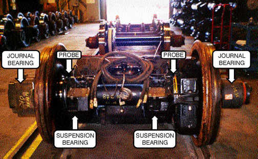
The train derailment initiated when the wheels of the lead axle of the trailing locomotive (VIA 6447) could no longer maintain gauge because of a fracture of the axle at a failed traction motor suspension bearing (Figure 2). Indication that the suspension bearing was in distress occurred well before the axle broke. An on-board hot bearing monitoring system activated an audible alarm in the controlling locomotive cab 35 miles east of Vancouver, but the system was subsequently disabled. The alarm activated about 29 hours before the derailment and less than two hours into the service life of a renewed traction motor/wheel set assembly.
1.2 Train Operation from Vancouver
1.2.1 Before Departure
Locomotive 6447, the trailing of three locomotives departing Vancouver on Train No. 2, had arrived in Vancouver on VIA Rail westward transcontinental Train No. 1 on the morning of Sunday, 31 August 1997, with the wheels on the lead axle scheduled for replacement because of normal service use. The afternoon shift foreman at the Vancouver Maintenance Centre (VMC) arranged overtime shifts for two technicians to install a previously built-up traction motor/wheel set assembly at 0300 on 01 September 1997. The same foreman would later communicate with the locomotive engineer of Train No. 2 on the evening of 01 September 1997 concerning the bearing alarm on this locomotive. The train crew operating Train No. 2 on the first leg of its eastward journey was not aware that a rebuilt traction motor/wheel set assembly had just been installed on locomotive 6447.
1.2.2 Vancouver to Mission
Train No. 2 originated in Vancouver at 2000, 01 September 1997, departing the station facility with 3 locomotives and 19 cars. While travelling between Ruskin, Mile 94.5, and Mission West, Mile 87.9, of the Canadian Pacific Railway (CPR) Cascade Subdivision, an alarm began to sound in the lead locomotive. The time was approximately 2130 and the train was approximately 35 miles from Vancouver Station.
There were no warning lights illuminated on the overhead console warning light panel or elsewhere in the cab of the lead locomotive. Based on the locomotive engineers' knowledge of the warning light panel, this indicated to them that the alarm originated in one of the two trailing locomotives. The locomotive crew members recalled that they initially suspected that the alarm was the result of a condition known as a continuous ground relay. A wayside hot box detector system that the train had just passed (located at Mile 96.8) had not generated any alarms; therefore, the outboard journal bearings were operating within an acceptable temperature range. Based on this information, the locomotive engineers concluded that the safety of the train was not in doubt. They believed that it would be safe to operate the train the remainder of the way to Mission Junction, Mile 87.0 of the CPR Cascade Subdivision, without restriction. They reasoned that it would be a safer place to perform an inspection and that they would be less likely to delay other traffic. At Mission Junction, also Mile 0.0 of the CPR Mission Subdivision, Train No. 2 diverged onto a connecting track where the first locomotive engineer (Engr 1) performed an inspection.
1.2.3 At Mission
1.2.3.1 Disconnection of the On-Board Hot Bearing Monitoring System
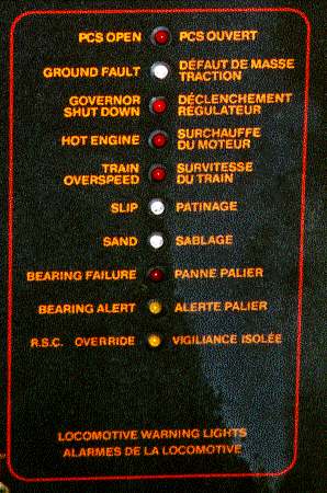
Engr 1 first went into the cab of the second locomotive (6437) and then into the cab of the third locomotive (6447) where a warning light was illuminated on the overhead console warning light panel. Without his reading glasses, he could not make out the text adjacent to the light on the panel. He radioed the second locomotive engineer (Engr 2), and from the description provided, Engr 2 concluded that the illuminated light corresponded to the "Bearing Alert" indication on the panel (Figure 3).
Engr 1 then detrained and, using the back of his hand, checked all the journal bearings on all three locomotives for evidence of heat. He climbed back into the cab of locomotive 6447 and called Engr 2 by radio. He advised him that he did not find a problem with the journal bearings.
At this point, the locomotive engineers decided to move the train a short distance ahead to position the locomotives under a light standard to provide better illumination for a more thorough inspection. Once locomotive 6447 was positioned under the light, Engr 2 also inspected the journal bearings on both sides of all three locomotives. No problems were noted.
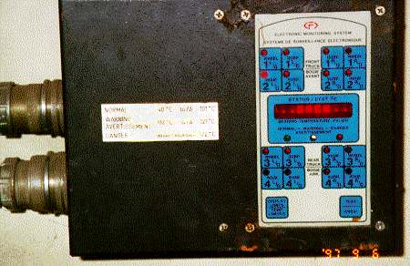
At the completion of his inspection, Engr 2 joined Engr 1 in the cab of locomotive 6447. They discussed a device (the Faiveley Monitor Box) in the short hood compartment of some VIA Rail locomotives. Engr 1 had some recollection of prior discussions with fellow employees concerning a device related to a bearing monitoring system located in the short hood compartment of this type of locomotive. Engr 2 then went into the short hood and located the device (Figure 4).
Engr 2 noticed a "test" button on the monitor box and depressed it, suspecting that the system might reset and thereby discontinue the audible alarm. He observed changes in the display after depressing the test button; however, the audible alarm continued to sound. Being unable to verify the reason for the alarm, the locomotive engineers decided that Engr 2 would return to the cab of the lead locomotive to consult his operating manuals while Engr 1 remained in the cab of locomotive 6447. Engr 1 recalled that, after a short time, the audible alarm stopped sounding.
At about this time, the CPR rail traffic controller (RTC) contacted Train No. 2, requesting information as to why their train was stopped on the drawbridge. The crew members advised that they were not actually on the drawbridge at Mile 0.8 of the CPR Mission Subdivision, but were occupying the signal circuitry for the bridge because of a suspected bearing problem. They advised the RTC that the problem would be rectified in a moment and that they would soon be off CPR track. The RTC indicated that there was a coal train approaching that would require the use of that track.
Engr 2 returned to the cab of the lead locomotive where he began to move the train towards Matsqui Junction, Mile 1.4. While doing so, he perused Canadian National (CN) General Operating Instructions for some information to help explain what the alarm meant. These instructions stated:
Instructions relating to VIA and AMTRAK passenger trains equipped with an on-board detector system will be issued by VIA and AMTRAK.
Neither he nor Engr 1 was aware of any additional instructions related to the on-board hot bearing monitoring system.
In the passenger train information section of the CN Time Table, Engr 2 found a reference to VIA 6400 series locomotives which stated:
VIA locomotives, numbered 6430 to 6458 are equipped with an on-board journal and suspension bearing monitoring system. VIA locomotives numbered 6400 to 6429 rely on wayside systems for journal monitoring.
Engr 2 had carried a copy (2nd edition) of General Motors (GM) F40PH-2D Operator's Manual that he had obtained from a former VIA Rail trainmaster. This manual did not provide him any definitive information to deal with the problem. Locomotive manufacturers' operating manuals are neither required to be carried by locomotive engineers while on duty nor are they consistently provided to locomotive engineers. However, Engr 2 located a copy of the GM F40PH-2D Operator's Manual (3rd edition) on one of the locomotives, and read the section "Hot Box Monitoring System." While this section contains information as to the operation of the hot bearing monitoring system in a single-locomotive application, it did not provide details as to what to do in the event of an indication. It did indicate that:
. . . In the event of a monitor failure, or, if a bearing temperature exceeds 121oC (249.8oF), the indication will be accompanied by an audible alarm . . . .
When the Danger Light is illuminated, there is an actual hot box.
Additional information within the manual on the overhead console warning light panel, as it pertains to the on-board hot bearing monitoring system indicated:
This Light indicates that a locomotive suspension or journal bearing has failed, normally at a temperature above 121oC (249.8oF). This Light may also indicate that the monitor is defective. When this Light is ON, the modulating buzzer will sound.
WARNING
If this Light comes on, applicable railroad instructions must be followed.
Neither he nor Engr 1 was able to locate any additional instructions from VIA Rail.
Shortly after Engr 2 began moving the train towards Matsqui Junction, Mile 1.4, the audible alarm began to sound again. While the train was stopped for the switch to diverge towards the CN Yale Subdivision, Engr 1 returned to the cab of the lead locomotive. The locomotive engineers decided to contact the on train services (OTS) service manager, who was on board the train, to request the use of his cellular phone to contact someone at the VMC for advice. Engr 1 met with the OTS service manager and conductor in the baggage car. Engr 1 recalled that, once communication with the Vancouver maintenance foreman was established, he identified himself, explained the continuous sounding of the alarm, the visual inspection and tests and the lack of wayside hot box detector system alarms, and asked if the alarm could be turned off. Engr 1 recalled that the foreman concluded from this that the system must have malfunctioned, said to "cut it out" and then explained how to do it. He further recalled that he disconnected the system in accordance with the instruction of the Vancouver maintenance foreman. He did not make a record of this action in the locomotive log book.
The Vancouver maintenance foreman recalled that he was asked by the locomotive engineer how to stop the alarm bells from ringing and that he had replied that the only way to do so was to disconnect the system. As an electrician by trade, the Vancouver maintenance foreman was aware of some reliability problems with the on-board hot bearing monitoring system. He recalled that he had explained to Engr 1 how to disconnect the system, but that he had not instructed him to do so. The Vancouver maintenance foreman made a record of the conversation in his log book, noting that a sensor on locomotive 6447 showed 120 °C, that the alarm bells were ringing, but that there was no hot box detected. He also noted that he was asked how to stop the alarm bells from ringing and that he had indicated that the only way was to "disconnect the plug in the nose" (i.e., the short hood of the locomotive). He recorded the conversation as having taken place at 2210 Pacific daylight time (PDT).
Neither the Vancouver maintenance foreman nor the locomotive engineers were aware that wayside hot box detector systems are designed to detect heat at the outboard journal bearing locations only and are incapable of detecting heat inboard of the wheels at the suspension bearing. The locomotive engineers had no knowledge of traction motor suspension bearings, their location, or function. The Vancouver maintenance foreman believed that training and knowledge of traction motor suspension bearings would be an integral part of locomotive engineer training.
The following morning, at approximately 0930 PDT, the Vancouver maintenance foreman contacted his manager from home and relayed the problems that he had encountered during his previous shift, specifically a minor runaway and the conversation he had had with Engr 1 of Train No. 2. During this conversation, the Vancouver maintenance foreman recalled having told the manager about the "hot box" problem and asked the manager to contact the maintenance foreman at Jasper, Alberta, to have him perform a bearing inspection.
After reviewing the customer service en route reports, which indicate on-time performance and problems encountered by trains, the manager concluded that, since Train No. 2 was operating on time and without further problems, he would not advise the maintenance foreman at Jasper.
1.2.4 Mission to Kamloops
At Matsqui Junction, Train No. 2 diverged onto the CN Yale Subdivision and continued eastward. The train stopped after approximately one half mile for the first station stop on that subdivision. While passengers and baggage were being loaded, Engr 1 detrained and inspected the journal bearings of the locomotives. Unable to locate a problem, he entrained and Train No. 2 continued eastward. The train passed a wayside hot box and dragging equipment detector at Mile 84.9 without indication of any problem. Still concerned with the unknown nature of the alarm and noting that the train was approaching 70 mph track, Engr 2 contacted the CN RTC and requested that the hot box detector operator verify the system reading. Approximately five minutes later, the RTC reported back that no defect had been detected. In an attempt to get further details that might help them resolve their concerns, the crew members requested that the RTC verify that the axles were all measuring "about the same" temperature. The RTC responded, indicating again that their train had a "clean bill of health," and offered to watch them over the next detector.
They continued to the next station stop at Chilliwack where Engr 2 relinquished the controls to Engr 1, detrained and inspected the journal bearings on the left side of the locomotives again without finding any indications of a problem. Between Matsqui Junction, Mile 87.9 of the CN Yale Subdivision and Chilliwack, Mile 71.8 of the CN Yale Subdivision, Train No. 2 had operated for approximately 7 miles at 70 mph. This marked the first time Train No. 2 had operated at this speed since the bearing alarm had sounded.
Train No. 2 departed Chilliwack and was operated without incident to Kamloops where the operating crew was changed. During the change-off, Engr 1 advised one of the relieving locomotive engineers that the hot bearing detection system on locomotive 6447 was "bad order" and had been disconnected at Mission. He further advised the crew that the train had been operated the remainder of the way to Kamloops without incident.
The train had been operated over nine additional wayside hot box and dragging equipment detectors, without indication of problems, since the alarm had been disconnected.
1.2.5 Kamloops to Jasper
The train was operated from Kamloops to Jasper, arriving at Jasper on time at 1335 having made up the delay incurred in the early stages of the trip. There were no difficulties experienced with the train during this portion of the trip.
1.2.6 At Jasper
Jasper was an inspection point for Train No. 2, with 35 minutes scheduled for the inspection tasks. As the lead locomotive on Train No. 2 was the spare locomotive for Jasper, the locomotive was set off. In addition, Jasper was a crew-change location and the away-from-home terminal for both Kamloops and Edmonton VIA Rail train crews. Arriving in Jasper, the inbound crew did not relay any information with respect to the alarm on locomotive 6447 to the relieving crew. Both locomotive engineers also contacted the Jasper maintenance foreman. They advised him of a lateral sway condition they noted in the lead locomotive; however, they did not advise him of the disconnected bearing monitoring system on locomotive 6447.
During the course of his inspection duties, the maintenance foreman looked into the small compartment in the short hood of the remaining two locomotives. Although the type of locomotive inspection prescribed to be performed at Jasper did not require him to examine the bearing monitoring system, he indicated that it was his practice to do so. He recalled that he noticed that the lower of the two plugs on the side of the monitoring system unit had been disconnected in the short hood compartment of locomotive 6447. He did not investigate this situation further. He knew that most VIA Rail locomotives were not equipped with this system and he presumed that it had been disconnected for legitimate reasons. Also, he recalled that it was not unusual to see the system disconnected on locomotives arriving at Jasper. He did not consider this system to be critical to the safe operation of the train, rather a tool that most locomotives did not have in any case. He did not discuss the disconnected bearing monitoring system with the outgoing Edmonton-bound crew.
1.2.7 Jasper to Edmonton
Train No. 2 departed Jasper on time with 2 locomotives and 19 cars. Between Jasper and Edmonton, Train No. 2 was operated without incident. The crew from Jasper changed off with a new crew in Edmonton and the new crew left eastbound with no knowledge of the previous bearing alarm and the disconnection of the bearing monitoring system.
1.2.8 Edmonton to Oban
The trip from Edmonton to the derailment location (Mile 7.5 of the CN Wainwright Subdivision at Oban) was uneventful. Approaching Oban, Train No. 2 was slightly ahead of schedule and being operated at a speed of about 67 mph; i.e., below the maximum permissible passenger train speed of 80 mph. The crew of a freight train had performed a passing inspection on Train No. 2 at Palo, approximately 8 miles west of Oban. During this inspection, crew members of the freight train had positioned themselves on the ground on either side of Train No. 2 as it passed. This inspection did not yield any indication of irregularities with the operation of Train No. 2.
1.2.9 Event Recorder Information Near Oban
Locomotive event recorder data indicated that, immediately before the accident, the train was travelling at 67 mph with brakes released, throttle in idle, headlight and ditch lights illuminating, and horn and bell sounding. Locomotive brake pipe pressure dropped rapidly from 97 pounds per square inch (psi) to 0 psi, indicating an emergency brake application attributable to a train separation. Speed decreased to 0 mph in a recorded time of 8 seconds.
1.2.10 At Oban
As a result of the derailment, data communication between the RTC's Centralized Traffic Control System (CTC) control panel and the east siding switch at Oban was interrupted. Noting that the switch was "out of correspondence", the RTC contacted Train No. 2 by radio to ascertain if there was a problem. The locomotive engineer responded, advising him that help was needed. He informed the RTC that the locomotives were on their sides and that he did not know the condition of the rest of the train. The crew of the train at Palo, having overheard this conversation, contacted the RTC and arranged signal authority over to Oban to render assistance. The outbound crew members who were to operate Train No.2 east from Biggar, having overheard the same conversation, contacted Train No. 2 advising the crew that they had notified the fire department and that help was on its way. They activated the Biggar community emergency plan, resulting in the notification of police, ambulance and fire department services.
1.3 Occurrence Site Information
1.3.1 Characteristics of the Derailment Area
The topography in the immediate area of the accident site was relatively flat. Highway 14 runs parallel with the track at this location approximately 200 m to the north. A secondary grid road extends off the main highway to the south and intersects the track. Also parallel to the track on the north side was a buried natural gas pipeline, approximately 100 m away. None of the derailed equipment came to rest over top of the pipeline. In addition, a large propane storage tank was located immediately adjacent to the east siding switch for the switch heater. The accident site was approximately 12 km west of Biggar and approximately 109 km west of Saskatoon, Saskatchewan. Biggar is serviced by a 13-bed hospital, a Royal Canadian Mounted Police (RCMP) Detachment, an ambulance service and a volunteer fire department.
1.3.2 Derailment Sequence
At a public crossing at Mile 8.76, the crossing planks sustained minor damage. Approximately 152 m east of this point, fragments from the fibreglass gear cover from the traction motor/wheel set assembly were found about the track. Approximately 76 m further east, marks on the gauge side of the head of the south rail began and continued east. At the Oban east siding switch, the west-end corner of a wheel flange guard rail located just to the gauge side of the south rail had been struck. The south wheel on the lead axle of locomotive 6447 had marks on the rim consistent with it having been jammed within the gauge of the rail. The tread of the same wheel had a triangular-shaped indentation similar in shape to the end corner of the guard rail.
The head end of the train came to a stop approximately 180 m from the position of the struck guard rail, with the two locomotives on their left sides and the first 13 cars derailed at various angles and orientations. The remaining six cars in the train did not derail.
1.3.3 Particulars of the Track
The Wainwright Subdivision extends from Biggar (Mile 0.0) to Edmonton, Alberta (Mile 266.7). At Mile 7.56, the authorized time table speed is 80 mph for passenger trains and 60 mph for freight trains.
The track at the accident location consisted of 136-pound continuous welded rail, manufactured and laid in 1985. The rail was laid on wood ties placed at 60 ties per 100 feet and the ballast was crushed rock. A No. 12 turnout was located at the east end of the Oban siding at Mile 7.56. A gravelled road crossing was located just east of the turnout at Mile 7.51.
All track components were in good condition and met Transport Canada's Railway Track Safety Rules. The track was tested by a track geometry car on 16 July 1997 and no deficiencies were detected. A rail flaw detection car tested the rail on 02 September 1997 and no defects were found. A detailed inspection of the turnout at Mile 7.56 was done on 25 August 1997 and no deficiencies were noted. Hi-rail and walking inspections of the turnout and track in the area of the derailment were performed by the track supervisor on 02 September 1997 and no exceptions were noted.
1.3.4 Rail Traffic Control
Train movements on the CN Wainwright Subdivision are governed by CTC and supervised by the RTC located in Edmonton. Normally, there are 10 to 20 trains per day each way on the Wainwright Subdivision, and only 3 passenger trains each way weekly.
1.4 Derailment Response
1.4.1 Train Crew and On Train Services Personnel
VIA Rail reported that there were a total of 198 passengers and crew on board the train at the time of the occurrence: 168 passengers, 4 train crew members, 25 working OTS employees and 1 off-duty OTS employee. Table 1 presents the train and locomotive consist of Train No. 2 from front to rear and the approximate locations of all passengers and crew.
Table 1
Passenger and Crew LocationFootnote 3
| Position in Train | No. | Rolling Stock Type (Function) | Passenger Capacity | Approx. No. of Passengers | No. of Crew | Total No. of Passengers & Crew |
|---|---|---|---|---|---|---|
| 1 | 6437 | Locomotive | 0 | 0 | 2 | 2 |
| 2 | 6447 | Locomotive | 0 | 0 | 0 | 0 |
| 3 | 8607 | Baggage | 0 | 0 | 0 | 0 |
| 4 | 8111 | Coach | 62 | 55 | 0 | 55 |
| 5 | 8121 | Coach | 62 | 20 | 0 | 20 |
| 6 | 8115 | Coach | 62 | 18 | 0 | 18 |
| 7 | 8406 | Diner | 48 | 0 | 2 | 2 |
| 8 | 8502 | Skyline (observation, food services) | 60 | 0 | 0 | 0 |
| 9 | 8305 | Manor (sleeper) | 28 | 0 | 4 | 4 |
| 10 | 8323 | Manor | 28 | 0 | 0 | 0 |
| 11 | 8340 | Manor | 28 | 0 | 7 | 7 |
| 12 | 8501 | Skyline | 60 | 0 | 0 | 0 |
| 13 | 8338 | Manor | 28 | 15 | 1 | 16 |
| 14 | 8322 | Manor | 28 | 10 | 2 | 12 |
| 15 | 8329 | Manor | 28 | 12 | 3 | 15 |
| 16 | 8303 | Manor | 28 | 7 | 0 | 7 |
| 17 | 8516 | Skyline | 60 | 0 | 0 | 0 |
| 18 | 8328 | Manor | 28 | 3 | 2 | 5 |
| 19 | 8221 | Château (roomette) | 29 | 14 | 1 | 15 |
| 20 | 8336 | Manor | 29 | 9 | 5 | 14 |
| 21 | 8710 | Park (observation, roomette and food services) | 58 | 5 | 1 | 6 |
| TOTAL | 168 | 30 | 198 |
At the time of the derailment, most passengers and OTS employees were asleep. The conductor and assistant conductor, located in diner car 8406, five cars behind the locomotives, recalled bracing themselves as the train derailed. They were thrown from their chairs onto the floor. Diner car 8406 came to rest at right angles to the track, leaning slightly to one side and completely detached from the cars ahead and behind it. After locating one of their portable radios that had become dislodged during the accident, the assistant conductor established communication with the locomotive crew, discussed their condition and determined thatarrangements were being made for assistance. Due to the darkness, they first went in search of flashlights. They located an emergency first-aid kit under a table and opened it. It did not contain any flashlights nor were there flashlights attached to the outside of the bag.
They then opened the end door of the diner car. The coach ahead (8115) was lying on its side, also completely detached from the train. A second coach (8111) was partially resting on top of it. The conductor immediately proceeded to coach 8115 to assess the situation and coordinate the evacuation. He entered the coach at one end and managed to crawl through the debris to mid-coach. As he made his way, he advised the passengers who he was, indicated that the immediate danger was over, requested that they stay where they were, remain calm and indicated that help was on its way. At the same time, he was making an assessment of the injuries and formulating an evacuation plan, and a service attendant was beginning to tunnel his way through the debris inside the car, carrying a sledgehammer.
The assistant conductor left the diner car and moved towards the rear of the train to find a flashlight and to liaise with the OTS service manager. First, he entered one of the sleeping cars where he believed he would find a multi-trauma medical kit and flashlights. He did not find either; however, he was eventually provided two flashlights by another OTS employee. He then encountered two other OTS employees with whom he began making arrangements for the evacuation. One OTS employee had located and carried with him a multi-trauma kit without flashlights. The assistant conductor continued towards the rear of the train where he located the OTS service manager in his sleeper compartment. Together, they detrained and began to make their way through the field to the overturned coach. On the way, they observed that there were power/telephone poles askew and that wires were hanging over some of the cars. They considered this a major hazard.
Outside coach 8115, the conductor, assistant conductor and the OTS service manager quickly conferred. The assistant conductor advised that the second and third coaches, 8111 and 8121, had been evacuated, except for one passenger who required a spine board. The OTS service manager briefed the conductor on the status of the passengers in the sleeping cars. The OTS employees stationed in the sleeping cars that had not derailed evacuated passengers through manor car 8322 to the road at a public crossing.
The OTS service manager then departed to assist and direct OTS personnel as they directed passengers who had been evacuated from the second and third cars, coaches 8111 and 8121, to a safe area.
At the fourth car, coach 8115, the conductor briefed the assistant conductor regarding the number of passengers, the injuries, the damage incurred and the equipment required.
The conductor had determined that only the passengers who were ambulatory and who were very near the end of the car would be able to evacuate through that door. He did not want to risk further injury to those who were trapped or immobile by having other passengers crawl over them to get out. He went around the coach to the other end, but quickly realized that, as a result of the damage incurred in the accident, this exit was not useable. Consequently, he decided to attempt to evacuate passengers through the emergency exit windows. To choose an escape route, he climbed up on top of the side of the coach where he noted what appeared to be power lines hanging approximately one foot above the coach. Fearing that the lines were energized, he climbed down off the coach.
By this time, a number of emergency response agencies were arriving at the scene. The RCMP was first to arrive, approximately 10 minutes after the accident, followed in no specific order by the Biggar Volunteer Fire Department, Saskatchewan Power, and Greenhead Health District Emergency Medical technicians.
The conductor explained his plan to evacuate the overturned fourth coach and expressed his concerns about the power lines. Emergency response personnel immediately de-activated the power lines. The conductor requested two ladders, one to climb up the side of the coach and the other to lower down into the interior, after they broke a window.
Before the emergency response personnel returned with the ladders, two OTS employees had broken one of the non-emergency windows using a sledgehammer. One started a small hole in the window, working from inside the car, and passed the hammer through the hole to the other working from outside the car, who finished knocking out the window. It was known that this was not an emergency exit window; however, the location was assessed as the best place from which to extricate the passengers who were not trapped and whose injuries did not prevent them from exiting in this manner.
When a large enough opening was hammered out, a multi-trauma kit and a flashlight were passed down into the car and the OTS employee who had been assisting from outside lowered himself into the car to administer first aid and assess the injuries. A ladder was immediately lowered into the car, allowing fire-fighters and emergency medical technicians to enter. Some passengers were evacuated through the window, others were strapped to spine boards and passed from one person to another and out the end of the car.
Emergency response personnel and train and OTS crew worked for approximately three and one half hours to evacuate the train. Although the majority of the passengers were evacuated within 20 minutes, the remainder of the time was spent extricating the passengers who were trapped in the wreckage.
1.4.2 Biggar Emergency Response Plan
The activation of the Biggar Emergency Response Plan and the actions of the relief VIA Rail crew at Biggar resulted in the immediate notification of a number of response groups including police, volunteer fire department, ambulance services and municipal officials. Simultaneously, CN rail traffic control personnel were initiating their emergency response plan.
Within 15 minutes of the derailment, the Biggar Volunteer Fire Department arrived at the scene. Local ambulance services arrived shortly thereafter. Upon arrival, first responders were given an immediate status report by train and OTS crew. Together, they coordinated their efforts to evacuate the passengers from coach 8115 and the remaining passenger from coach 8121.
The fire department extinguished a small grass fire on the north side of the track and established two triage sites, one outside coach 8115, the other near the crossing. They also set up external lighting, arranged for municipal officials to open the town hall to provide temporary accommodations for the passengers that had been evacuated, and coordinated the transportation of passengers to Biggar on school buses.
Once evacuated from the train, seriously injured passengers were taken to hospital by ambulance. The remaining passengers, OTS and train crew were transported to the Biggar community town hall. There, they received a second medical assessment, as a result of which some were taken to hospital for treatment.
At approximately 0530, after having ensured that all the passengers had been evacuated from the train, the conductor departed the accident site for the town hall.
1.4.3 Post-Accident VIA Rail Response
Subsequent to the accident, local representatives from VIA Rail began making arrangements for handling and accommodating passengers, as they arrived in Biggar. Situation updates were provided regularly and railway representatives were present to answer questions. Baggage and personal possessions were retrieved from the train and efforts were made to return them to the appropriate passengers. Alternative travel arrangements were provided for passengers from Biggar to their respective destinations by VIA Rail.
1.5 Train Information
At the time of the derailment, the train consisted of 2 locomotives and 19 stainless steel, Head End Power (HEP) passenger cars. It weighed approximately 1,100 tons and was approximately 1,700 feet in length.
1.5.1 The Locomotives
Train No. 2 was powered by GM F40PH-2D locomotives. This type of locomotive is configured with the short hood leading. The car body is fully enclosed, providing internal walkways for access to the engine room. It is a four-axle, 3,000-horsepower, diesel-electric locomotive intended for passenger service. The main generator of the locomotive converts mechanical energy created by the 16-cylinder turbocharged diesel engine into electrical energy. The electrical energy is distributed through the electrical panel to the traction motors, each of which are geared to a pair of driving wheels.
A secondary electrical alternator for providing electric heating, air conditioning, lighting and power for the entire train is standard equipment on this type of locomotive. Operating controls for this alternator are located in a HEP control panel in the cab of the locomotive.
1.5.2 HEP Stainless Steel Passenger Cars
VIA Rail's HEP stainless steel cars were originally designed and built in the mid-1950s and have since been refurbished by VIA Rail for use in transcontinental service. The cars have a length of 25.9 m between couplers and an overall width of 3 m. This equipment has a height of 3.6 m. The park and skyline cars are topped with an observation dome and have a total height of 4.3 m. The car bodies and outside shells of the cars are made entirely of stainless steel. All power is supplied to the cars by the HEP system on the locomotives and train-lined throughout the train.
Subsequent to the VIA Rail passenger train occurrences at Brighton, Ontario, and Blue River, British Columbia,Footnote 4 a modification schedule for passenger cars was developed by VIA Rail in early December 1994 to address shortcomings in passenger safety. Because of high ridership, passenger cars operating on trains between Québec, Quebec, and Windsor, Ontario (VIA Rail's high-speed corridor), were given top priority for modification. Cars in that fleet were modified by the end of 1996. VIA Rail's HEP stainless steel fleet in use in transcontinental service and its remaining passenger rolling stock were to be modified next. Work on modifying the HEP fleet commenced in early 1997. At the time of this derailment, the modifications to the HEP stainless steel cars were approximately 50 per cent complete. In addition, some cars had been returned to revenue service with the modifications partially complete. Two of the cars on Train No. 2 had been fully modified. The intention was to complete the modifications after seasonal demands diminished. The result was that, in the interim, before the completion of the modification to all cars, some trains, such as the occurrence train, comprised cars that were fully modified, partially modified or not modified at all. This created some confusion in the aftermath of the derailment as train and OTS crew searched for multi-trauma medical kits in sleeping cars that had not been modified. The modification required a multi-trauma medical kit in all sleeping cars.
During the course of the investigation, other VIA Rail transcontinental trains were surveyed and, in some cars, emergency signage had been posted as per the modification requirements, but the referenced safety equipment was not available in the location indicated.
1.5.3 Damage to Equipment
As a result of the derailment, three cars were damaged beyond economic repair. Six other cars sustained considerable damage, but were assessed as repairable. The remaining 10 cars were returned to service after having all the wheel sets renewed and undergoing various minor repairs. Both locomotives were assessed as repairable.
1.6 Locomotive On-Board Bearing Monitoring System
VIA Rail's F40PH-2D locomotives, road numbers 6430 through 6458, as well as Bombardier locomotives, road numbers 6900 through 6930, were equipped with an on-board journal and suspension bearing temperature monitoring system. Together, these locomotives represent almost half of VIA Rail's locomotive fleet.
A similar on-board bearing monitoring system is also on all VIA Rail's Light, Rapid, Comfortable (LRC) cars.
On-board bearing monitoring capability was required by CN as a condition of its approval for VIA Rail to operate high-speed passenger trains on CN track in the Québec/Windsor corridor. At that time (early 1990s), the technology in wayside hot box detector systems could not be relied upon to detect overheated journal bearings at speeds above 80 mph. Furthermore, wayside hot box detector systems were designed to focus on the bearings external to the wheels, the journal bearings, and as such maximize detection of problems on freight rolling stock.
Both the wheel bearings on LRC passenger cars and locomotive traction motor suspension bearings were inboard of the wheels, away from the focus of the heat sensors of the wayside hot box detector systems. CN's requirements were intended for the inboard bearings on the LRC cars and the journal bearings on locomotives for captive high-speed service. VIA Rail purchased locomotives equipped with an on-board bearing monitoring system that not only monitored the outboard journal bearing, but included a traction motor suspension bearing within the system's monitoring capability.
The bearing monitoring equipment installed on the F40PH-2D locomotives was supplied by a company called Faiveley Ltd. It is referred to as the HB-16 model and is capable of continuously monitoring 16 bearings (8 journal and 8 suspension) through strategically placed heat detection sensors. The system consists of a 16-channel electronic monitor, associated cabling, junction boxes and temperature sensors. The monitors were mounted in the short hood of each locomotive in a small closet-type enclosure, permanently affixed to the left wall at such a location that it was behind a narrow entrance door when opened. Access to the monitor was also made difficult by the narrow door and small compartment.
There were two electrical connectors attached to the monitor identified as JK1 and JK2. The JK1 was a 24-pin connector that attached the wiring from the eight suspension bearing temperature sensors, and the JK2 was a 37-pin connector that attached the direct current (DC) supply to the monitor, the wiring for the eight journal bearing temperature sensors and the six contacts for the internal warning and danger alarms. The temperature sensors, or probes, were embedded in the outer journal (truck support) bearing and inner suspension (traction motor support) bearing housings, located respectively on either side of each of the eight locomotive wheels. The system measures the temperature of each probe every second to establish whether it is within pre-determined allowable ranges (Figure 2).
The system monitor on the LRC cars is mounted behind glass in the corridor of each car. Its display is visible to train personnel from the corridor.
On the front surface of the monitor (Figure 4), there is a system status display consisting of 16 membrane switches, one for each bearing, a status display window, normal, warning and danger light indications, a display limits switch and a test switch. When any of the membrane switches for the individual bearing probes is depressed, the temperature of the bearing is displayed, in °C, in the status display window, unless a probe has malfunctioned. The bearing membrane switches also have "abnormal indicating lights" that illuminate to show the location of an abnormal condition. The normal, warning and danger lights are immediately beneath the status display window. The normal light displays green when there is no fault, and the system is functioning with all temperature sensors below 102 °C. When the warning light displays yellow, there is an abnormality. A bearing may be in early stages of failure when operating between 102 and 121 °C or there is a fault in the system. When the danger light is illuminated, a bearing has reached a temperature above 121 °C. The display limits switch, when depressed, will recall from memory any bearing which has exceeded 101 °C and display the highest recorded temperature and location in the status display window. When depressed, the test membrane switch will cause the system to cycle through all the monitored circuits and display those circuits that are operating in the normal temperature range, as well as those that have exceeded the normal temperature range or have a circuit fault.
The system is capable of multiple-unit operation through a train-line connection between locomotives. In each locomotive, it is connected to an overhead console warning light panel directly above the locomotive engineer's seat (Figure 3). The right-hand side of the panel is designated for locomotive warning lights, and the left-hand side of the panel is designated for train warning lights. On the locomotive side of the panel, there are 10 lights assigned to different locomotive warnings. The second and third lights from the bottom of the panel are identified as "Bearing Alert" and "Bearing Failure" respectively; however, these lights do not differentiate between journal and suspension bearings or indicate the location. When illuminated, the "Bearing Alert" displays greenFootnote 5 and the "Bearing Failure" displays red.
An audible intermittent alarm activates in all locomotives of a multiple-locomotive consist when certain faults occur. Some of these faults are associated with the overhead console warning light panel and some are associated with the engine control panel indicating light panel. The audible alarm is the same for each of the different panel indications for which it is sounded. The audible intermittent alarm activates for these faults:
- Bearing failure
- Ground fault
- Hot engine condition
- No power charger
- Governor shut down
- Blended brake lockout
- Wheel Slip
The nature of the problem is indicated by the annunciator lights on the overhead console warning light panel or the engine control panel indicating light panel. If the problem is in a trailing locomotive, the crew will have to check the overhead console warning light panel of the other locomotive(s) to determine on which locomotive the problem is. The one exception to this is the wheel slip indication, which is train-lined through a multiple-unit jumper cable allowing a visual indication in the leading locomotive.
With respect to the locomotive hot bearing monitoring system, the alarm will sound in all locomotives when a bearing failure has occurred; however, it will only be accompanied by the failure warning light in the locomotive on which the bearing failure has occurred. A bearing alert indication (green light) will only illuminate on the locomotive on which the alert has occurred and will not be accompanied by the audible alarm on any locomotive in a multiple-locomotive consist. Standard convention of colour indicators for safety warning systems utilizes green to indicate a safe condition.
VIA Rail had suspected that the on-board bearing monitoring system temperature-sensing probes that were mounted externally near the journal bearings were causing the majority of the system reliability concerns. This, in conjunction with improvements to the wayside hot box detectors, resulted in VIA Rail implementing a modification to remove the temperature-sensing probes from the journal bearings on locomotives 6430 to 6458.
The TSB Engineering Branch examination of the on-board hot bearing monitoring system on locomotive 6447 (report LP 148/97Footnote 6), both at the occurrence site and in the laboratory environment, led to the following conclusions:
- The on-board journal and suspension bearing temperature monitor "0035A" on locomotive 6447 was found disconnected at the JK2 connector after the derailment.
- Monitor "0035A" was serviceable at the time of the derailment.
- Monitor "0035A" had a recorded temperature of 138 °C at the L1 suspension bearing location which was coincident with the axle that later failed. (The temperature was recorded before the JK2 cable was disconnected.)
- The audible alarm that sounded 35 miles from Vancouver was the result of the L1 suspension bearing temperature sensor on locomotive 6447 reaching a temperature in excess of 121 °C.
- Monitor "0035A" had recorded eight open circuit suspension bearing probes and two open circuit journal bearing probes, L1 and L3.
- The cause of the eight open circuit suspension bearing probes and two open circuit journal bearing probes could not be conclusively determined.
- There was continuity in the suspension bearing wiring and sensors before the derailment.
- The monitor's power supply does not have any over-current protection.
1.7 The Axle
1.7.1 Traction Motor Friction-type Suspension Bearings
Traction motors are suspended from locomotive axles between the wheels of each respective wheel set at suspension bearings, located on each side of a traction motor. The suspension bearings allow the free rotation of the axle, and serve as suspension points for the traction motor, while withstanding forces due to traction motor torque. Friction-type bearings are most common to this application and have been successfully used for decades throughout North America. Lubrication of these bearings is achieved through a wick system. The bottom end of the wick is suspended in a reservoir of oil while the top end maintains contact with the axle surface through a window in the bearing shell. A spring mechanism is designed to maintain constant contact of the top end of the wick against the axle. The wick material draws oil up from the reservoir to the axle surface. As the axle rotates, a thin film of oil coats the axle surface to protect the bearing against heat and abrasion associated with friction. Copper-based (bronze) bearing shells, which form a cylinder around the exterior of the axle, are lined with a low-friction alloy, called "babbitt". Babbitt is usually comprised of tin, antimony and lead. A friction bearing, functioning properly, has adequate lubrication between the machined surface of the axle, at the bearing location and the babbitt liner of the bearing shell.
Torque is applied from one side of the traction motor, through a pinion gear, to a bull gear on the axle. The side of the axle receiving the power has historically proven to be more susceptible to failure. The axle that failed on locomotive VIA 6447 also failed on the gear side.
1.7.2 Build-up and Installation of the Traction Motor/Wheel Set Assembly
On 28 August 1997, an axle and wheel assembly, a wick assembly and suspension bearing shells were combined with a traction motor at the VMC in a process called a 'build-up'. It was standard practice to have a traction motor/wheel set assembly prepared in advance of it being needed. The build-up process was completed by an experienced, qualified technician who recalled experiencing no anomalies during the procedure. The build-up procedure usually takes about four hours to complete.Footnote 7
The axle used in the build-up was manufactured in 1986. It had last been reconditioned and requalified in April 1997, at which time a new set of wheels had been pressed on the axle. As part of standard procedure, the dimensions of the axle had been returned to specifications for requalification for service. However, a magnetic particle inspection was not performed. This inspection allows the detection of shallow cracks and is an Association of American Railroads (AAR) and a VIA Rail requirement. The contractor who requalified this axle did not have the required equipment to perform this test.
After accumulating 30,000 miles in service, the traction motor was removed for servicing because of a minor electrical problem in April 1997. It was also reconditioned at a VIA Rail-approved supplier with whom the railway had a long-standing relationship.
This was the first installation of both the axle and traction motor since servicing. The use of reconditioned components is normal industry practice. VIA Rail believed that both these components met specification before use.
The wick assemblies used for supplying lubricating oil from the oil reservoirs on the traction motors to the axle/bearing interface were new and ordered directly from a long-standing GM-approved supplier. The wick assemblies were shipped pre-soaked and individually seal-wrapped to prevent contamination. Before installation, GM specifications required the wick assemblies to be soaked in an oil bath at room temperature for a minimum of 20 minutes to ensure saturation, if it was suspected that the wick had dried during storage. It was common practice at the VMC to soak them a minimum of 24 hours. The wick assembly from the non-gear side examined after the accident had no apparent anomalies. The wicks on both sides were oil-saturated.
The suspension bearing shells were new and supplied directly from a GM-approved supplier. VIA Rail uses only new bearing shells while some other North American railways use requalified bearing shells as well as new bearing shells. The pieces examined after the accident were within the specifications of the manufacturer, GM and VIA Rail.
When a newly built-up traction motor/wheel set assembly is being installed into a locomotive, the suspension bearing oil reservoirs are filled with the lubricating oil from a can designated for that purpose. The can is filled elsewhere within the shop and returned to the area where the assembly is installed. Other workstations within the shop are equipped with oil dispensers. Oil is piped directly to the job site and dispensed through a hose reel, minimizing the handling and associated risk of contamination. When examined after the accident, the oil reservoirs on the traction motor that failed were noted to have sufficient lubricating oil to wet the bottom of the wicks. Oil analysis was performed.Footnote 8 The oil met the VIA Rail specification and, except for viscosity, it was found to be within GM's specification. The viscosity was lower than recommended by GM. The use of oil of this specification is not unique to VIA Rail.
A number of potential sources of contamination to the build-up process were identified throughout the VMC: the build-up area is in an open shop area approximately 10 m from the drop table where wheel assembly change-out takes place and approximately 20 m from an in-floor wheel lathe; the shop doors are frequently open to allow equipment being serviced to move into and out of the servicing bays; and trades people within the shop use electric or oxyacetylene welding equipment, compressed air, cleaning apparatus, forklifts, and other tools which can generate smoke, dust or other airborne particulate matter.
1.7.3 History of Railway Axle Failures Caused by Liquid Metal Embrittlement
Studies of failed railway axles circa 1914 identified that liquid bronze bearing metal had penetrated axle surface cracks in the region beneath the support bearingFootnote 9. In the 1940s and 1950s, the term "copper penetration failure" had emerged and it was believed to occur in the following sequence:
- the bearing surface is heated by friction because of a loss of lubrication;
- the babbitt metal lining melts;
- the babbitt metal is displaced, possibly by mechanical action or volatization;
- the bronze backing is heated to its melting point and penetrates the axle, causing failure.
There is now a large quantity of accumulated research on this subject and it is known that there are a number of forms of what is now described as "liquid metal embrittlement" (LME). LME is loosely described as the phenomenon in which the ductility of a solid metal is reduced by exposure of the surface to a liquid metal. The loss of ductility results in a reduction in the axle toughness. Toughness is the property which gives a material its resistance to crack initiation and propagation.
The use of the same materials in the manufacture of friction-type traction motor suspension bearings continues today; however, most new locomotives purchased in Canada since the mid-1980s are equipped with a maintenance-free roller bearing system for traction motor attachment. The number of suspension bearing failures (any condition that resulted in a suspension bearing being removed from service before normal service replacement) reported for CN, CPR, and VIA Rail has been stable for 1994, 1995, and 1996, averaging a combined 39 confirmed failures per year. VIA Rail experienced no failures in 1994, and one in each of 1995 and 1996. Subsequent to this failure, two failures were picked up by detectors in 1997 in sufficient time to avoid catastrophic failure. Based on bearing performance, and the costs involved, there is no plan within the railway industry to convert existing traction motor suspension bearings to a roller bearing system.
A research project, funded by the Transportation Development Centre of Transport Canada, is currently under way at the National Research Council of Canada Laboratories, in Ottawa. The research project, administered by the Railway Research Advisory Board, is to research alternative materials less prone to contribute to LME for potential use in friction bearings.
1.7.4 The Bearing and Axle Failure on Locomotive 6447
The traction motor assembly, which contained the failed axle, was removed from locomotive 6447 at the accident site and shipped to CN's repair shop in Saskatoon, where the axle and bearings were removed. All the traction motor components were then forwarded to the TSB Engineering Branch for examination and testing.Footnote 10
From the laboratory analysis, it was determined that a lack of lubrication caused overheating and melting of the bearing and babbitt material in contact with the axle. The liquid metal penetrated the axle surface on a microscopic level, causing a loss of axle ductility. This resulted in numerous cracks initiating around the axle surface. These cracks then progressed towards the centre of the axle. This reduced the effective cross-sectional area of the axle to the point where normal service loading could no longer be sustained, resulting in catastrophic failure. Extensive damage to the axle, bearing and lubrication system precluded the determination of the cause of the lack of lubrication.
1.7.5 Past TSB Safety Action on Axle Failures
On 18 December 1992, CN eastward freight Train No. 218 derailed near Oakville, Manitoba, resulting in the release of dangerous goods and the evacuation of the town. The Board determined that the derailment resulted from a locomotive axle failure arising from inadequate lubrication of a traction motor suspension bearing (TSB report R92W0300). In consideration of the consequences associated with any kind of locomotive axle failure, the Board recommended that:
The Department of Transport urge all Canadian railways to implement heat detection systems on locomotive suspension bearings to warn crew members of failing bearings.
Transportation Safety Recommendation R94-08
In response, Transport Canada studied information on bearing failures from Canadian and American railways and concluded that the risk of a suspension bearing failure was very low. Therefore, modifying the existing motive power fleet with a heat detection system would not be justifiable. Moreover, the current locomotive fleet equipped with friction suspension bearings will be eventually replaced with locomotives equipped with the newer style roller suspension bearings. To facilitate risk monitoring, Transport Canada required that all federally regulated railways report each occurrence of a suspension bearing found overheated or failing while in service.
1.7.6 Quality Assurance
Until 1994, VIA Rail had staff dedicated principally for the purpose of quality assurance. These individuals performed audits to ensure that components complied with specifications, and that quality control methods and practices were applied. In a company reorganization, these positions were eliminated and the responsibilities were re-assigned to those employees actually performing maintenance tasks. As well, VIA Rail removed its quality assurance personnel from its major suppliers' facilities and relied on the quality assurance programs of those suppliers and the fact that they were certified by the AAR.
With regards to wheel shop work, VIA Rail supervisors at the Montreal Maintenance Centre (MMC) stated that they personally checked all VIA Rail's wheels at the MMC upon arrival from the contractor wheel shop, as well as before delivery to the VMC. At the VMC, personnel stated that it was standard practice to check all wheel set assemblies upon arrival. Also, designated VIA Rail employees at the VMC performed random non-conformance inspections as a form of quality control, although not as frequently as was performed before disbanding the quality assurance group. The VMC had a quality assurance manual that was prepared in 1990, and last revised in 1996. Since the accident, the VIA Rail examination of wheel set/axle assemblies upon arrival at the VMC revealed that 19 of a total of 34 had defects in the suspension bearing seat area, including scratches, dents, corrosion pits, chain damage, and protective coating damage. VIA Rail has increased its monitoring and inspection of transported wheel sets subsequent to the identification of these defects.
1.7.7 Maintenance and Inspection Records
Before the derailment, railway maintenance and inspection practices did not provide any additional inspections for suspension bearings on renewed traction motor/wheel set assemblies during the first few hundred miles in service. During this 'break-in' period, new plain bearings can be prone to failure. It had once been the practice for some mechanical departments to allow freight cars with new, plain journal bearings to make one trip empty before being placed into service. This gave the new bearings a chance to 'seat-in' during this vulnerable break-in period. In addition, train crews were often advised of the presence of cars with new bearings on their trains, and the cars were placed where they could be observed by the train crew. While the newly built-up traction motor/wheel set assembly was momentarily spun to ensure that the gear teeth were properly lubricated before application to the locomotive, no such consideration was given to seating in the suspension bearings.
A review of the VMC repair records for VIA Rail locomotives 6447 and 6437 indicated the following discrepancies from the VIA Rail master maintenance repair schedule:
- some repair records did not note that the work was completed;
- work performed was not always done as frequently as specified in the maintenance schedule;
- scheduled modifications were not always completed on time;
- repair records did not always accurately reflect the work that was performed; and
- required supervisory approvals were not always shown on work records.
Furthermore, some shop staff, including supervisory personnel, were not using or aware of the quality assurance manual.
Log defect books for seven locomotives were reviewed and entries were noted pertaining to operating problems associated with the on-board hot bearing monitoring system. Examples of defects noted were open probes, loose wires, and one 'continuous beeping'. The entry for the 'continuous beeping' showed that the system was disconnected in Winnipeg, and the action taken section shows that a suspension bearing probe was repaired and the system was reconnected in Toronto.
1.8 Passenger Safety
1.8.1 Passenger Equipment Safety Features/Supplies
1.8.1.1 Posted Safety Information
A non-illuminated aluminum coloured plaque measuring approximately 25 cm (10 inches) by 15 cm (6 inches) was mounted on the inside wall at both ends of each car. The plaque contained a pictogram of the car depicting the number and location of the emergency exits, location of emergency tools and written instructions in English and French on how to use the emergency hammer to break an emergency exit window.
Inside the passenger cars, emergency exit windows were identified by a non-illuminated decal depicting a hand holding a mallet-like hammer and the words "Emergency Exit" in English and French. The hammer depicted on the decal was blunt at both ends, while the hammer provided was blunt on one end and had a pointed tip on the other end, especially designed to penetrate tempered safety glass.
1.8.1.2 Emergency Tools
A set of emergency tools (sledgehammer, crow bar, hand saw, and axe) was located in each car. The tools were secured in a recessed cabinet protected by a transparent plastic panel mounted on a metal frame with a piano-hinged door. There were two closing mechanisms on the door and a double-ringed handle which was sealed. To remove the tools, the seal had to be broken, the door opened, the tie-down straps unfastened and the metal retaining bar rotated. In the aftermath of this accident, difficulty was encountered by some OTS crew attempting to access the tools, specifically locating the recessed tool cabinet, rotating the metal retaining bar and extricating the tools. There was no hands-on training on the removal of the emergency tools, and the existence and operation of the retaining bar was not indicated in the emergency procedures training manual.
1.8.1.3 Fire Extinguishers
There were a total of 42 fire extinguishers on Train No. 2. Five-pound CO2 extinguishers were mounted on the kitchen wall of each food preparation car (one diner car and three skyline cars). Two and one half pound dry chemical extinguishers were located in recessed wall cabinets at each end of other cars. There were two 30-pound dry ABC-type dry chemical fire extinguishers on each locomotive (one in each cab and one in each engine compartment).
A number of fire extinguishers from Train No. 2 were used in an attempt to extinguish a small grass fire that occurred shortly after the derailment. The fire was extinguished by the Biggar Volunteer Fire Department.
1.8.1.4 Multi-Trauma Medical Kits
On transcontinental trains, in addition to the small first-aid kit located on each car, the practice of the railway is to carry a multi-trauma medical kit in each food preparation car (diner and skyline cars). There were four such cars on Train No. 2. The multi-trauma medical kits comprised a black vinyl bag with a zipper closure containing medical supplies to stabilize individuals with various types of injuries. An unbroken green plastic seal fastening the zipper tabs together indicated that the kit was stocked. A non-fluorescent white cross inside a green circle was located on the exterior of each multi-trauma medical kit. Also, velcro loops, which held four standard, double 'D' cell flashlights and an orange fluorescent armband, were located on the exterior of the kit. A dark blue strap on one end of the bag served as a handle.
Train No. 2 was equipped with three multi-trauma medical kits and one emergency first-aid kit, which was the type that preceded the current standard. These kits were stored in lockers at one end of each car. The lockers used to store these kits contained many other supplies used by OTS crew, including linen and food. The service attendant responsible for the car normally had the master key for all the locks on the car. During the daytime and throughout the evening, the lockers were not usually locked; however, they were locked at night from approximately 2330 until 0530. The service attendant or the chef, whoever intended to be up first in the morning, retained the master key throughout the night.
It is estimated that there were two or three serviceable flashlights on the train and these were used during the evacuation. The remaining 13 flashlights required for the trauma kits were either missing or unserviceable. Although the OTS crew was trained to do pre-departure safety checks, emergency flashlights were not part of that safety check. There was no "Pre-Departure Safety Check List."
1.8.1.5 Emergency Blankets
Emergency blankets were contained in black vinyl kits similar in shape, size and colour to the multi-trauma medical kits. These kits were stored in the same locker as the multi-trauma medical kits. A green plastic seal fastening the zipper tabs together indicated that the kit was fully stocked. Non-fluorescent, white lettering on the outside of the bag read "Couvertures de sauvetage - Rescue Blankets." A dark blue strap on one end of the bag served as a handle. During the evacuation, an OTS crew member who was attempting to retrieve a multi-trauma medical kit obtained a kit containing emergency blankets by mistake.
1.8.1.6 Emergency Lighting System
When the locomotive-generated electrical current is discontinued, an emergency electrical supply source is automatically activated. The 60-volt DC for emergency lighting is provided directly from batteries, filled with acid, located under each car. Emergency power is distributed to all breakers identified as "Emergency" on the DC distribution panel located on the lower part of the centre door of the electrical locker. Emergency breakers identified include marker lights, aisle fluorescent lights, vestibule lights, passage incandescent lights, washroom lights, lounge lights, bedroom and roomette lights. This emergency power supply is available for approximately two hours. The circuits are automatically shut off when the battery voltage falls below 55 volts. Emergency lighting is not as bright as normal alternating current (AC) lighting. There is no exterior lighting on this passenger equipment.
As a result of the derailment, head-end power was terminated, activating the emergency lighting systems. The battery unit on coach 8115 sustained damage, rendering the emergency lighting systems inoperative. Sleeping car 8340 came to rest at such an angle that acid leaked out of the batteries. The emergency lighting system on that car did not work. Without emergency interior lighting, it was difficult for passengers and crew to locate the nearest exit. The lack of interior emergency lighting also created problems for crew members and emergency first responders attempting to account for all the passengers, assess injuries, administer first aid and evacuate the train.
With the exception of the step and aisle lights in the observation domes, emergency lights throughout the train were located in the ceiling. Safety design principles recommend that lighting used to illuminate emergency egress pathways be located at or near ground level to remain visible if smoke is present. Smoke will generally rise, leaving lower areas with better visibility. Of course, the effectiveness of ground level emergency lighting is also dependent upon whether the car remains upright after an accident.
In those cars where the emergency lighting worked, crew members commented that the light provided was insufficient. For example, with only emergency lighting to aid them, crew members experienced great difficulty distinguishing the emergency tool cabinet door from the wall itself, even though they knew where the cabinet was located.
In some of the personal compartments in sleeper cars 8338 and 8322, the emergency lighting system did not self-activate; however, it did come on automatically in other areas of those cars, including other personal compartments. In some cases, occupants stated that they were able to "turn a light on using the normal switch"; i.e., manually activate the emergency lighting system. VIA Rail advised that the lighting system was designed to operate in this manner to minimize
disruption to passengers during normal switching operations. Without lighting, passengers and crew experienced disorientation and difficulty locating the personal effects they required to exit the train such as glasses, shoes, and clothes.
Several passengers and crew were injured departing the train into darkness, reportedly jumping from as high as 4 m to the ground below. Others were injured when they fell, walking through the fields outside and in proximity to the train.
1.8.1.7 Doors, Steps and Windows
Access onto most VIA Rail cars is through the manually operated, side entrance doors (one on each side of the car) which open into a vestibule located at one end of the car. Diner cars have no side entrance doors. There were no posted written instructions to advise how to operate the side entrance doors, which are the primary exits in an emergency evacuation. However, if the car remained in its normal position following an accident, these doors could easily be opened. Manually operated retractable stairs, located beneath a trap door in the vestibule floor, facilitate access to and from track level. No instructions were posted to advise of the proper operating method of the retractable stairs.
There was no indication that the operation of the side entrance doors and retractable stairs presented problems in this occurrence.
Throughout the equipment, hinged corridor doors permit passenger and crew movement between cars. On the cars that remained upright during the derailment, the hinged corridor doors operated easily and did not hinder through traffic during the evacuation.
An emergency exit door was located in the park car, at the rear end of Train No. 2. There were no signs to indicate that it was an emergency exit or how to operate it. Its use was not required during the evacuation.
Emergency exit windows consisted of two 6 mm (1/4 inch) panes of tempered glass, separated by an air space. They measured 0.66 m (26 inches) high by 1.07 m (42 inches) wide. Coaches, sleeping cars, observation cars, and diner cars each have four emergency exit windows, two on each side of each car. Each emergency exit window had a non-illuminated pictogram of a hand holding a mallet-like hammer and the words "Emergency Exit." The location and orientation of the emergency exit window hammers on the occurrence train were inconsistent. Some hammers were located to the right of emergency exit windows while others were to the left. In some instances, the emergency hammer was not within the field of vision of the person(s) seated beside the emergency exit window. The metal boxes containing the hammers were mounted either horizontally or vertically. It was not readily apparent how to remove these hammers. There was no information to suggest that difficulties with these emergency exit hammers were encountered during this occurrence.
Emergency exit windows in sleeping cars are located in common passageways and some personal compartments (bedrooms or roomettes). Personal compartment doors may be locked from the inside. Master keys are held by service coordinators and the OTS service manager only. Notwithstanding that the sleeping cars were of a standard design, when a sleeping car is on its side, difficulties with respect to passenger egress can arise. For example, if the aisle is at the bottom, passengers wishing to escape through an emergency window must open the cabin door and climb up on the room furnishings to break the window overhead. If the aisle is at the top, passengers must climb upward out of the cabin door and negotiate the narrow aisle to locate an emergency exit window or reach an end door.
There were no emergency exit windows in the domes of the skyline and park cars.
1.8.1.8 Emergency Exit Seating
In VIA Rail's Emergency Responses Procedures Training, Module 2 - Be Prepared, one of the stated objectives is to identify situations that may compromise the safety of customers travelling on board. The example provided to crew members was "an elderly couple, or mother and child, seated at an emergency exit window." Such passengers may not be physically able, or willing, to assume the responsibility of opening an emergency exit; if so, they should be relocated. This procedure was not consistently followed at the time of this occurrence.
1.8.2 Other Pertinent Car Features
1.8.2.1 Securement of Carry-on Baggage
Carry-on baggage on the coaches was not secured. VIA Rail allowed passengers to store their baggage in the overhead baggage racks, under the seats, on unoccupied seats or in the end baggage compartments. The overhead baggage racks have only a small lip or ridge intended to prevent baggage from sliding off but, apart from LRC passenger cars used in the Québec/Windsor corridor, there is no latched door or similar barrier to prevent baggage from flying into the compartment during an accident. Similarly, the end baggage compartments have an open bay design which allows for easy stowage and retrieval of larger pieces of luggage. There is no mechanism to secure this luggage once it is stored. This is the normal situation in the railway industry; it contrasts with the air travel industry where government standards and regulations strictly govern the storage of baggage.
In bedrooms and roomettes, carry-on baggage is stored in "open cubbies" or in end baggage compartments on the château and park cars. Neither the open cubbies nor the end baggage compartments were equipped with any mechanism to secure baggage.
In VIA Rail's General Instruction to Train Conductors, it is recommended that customers limit themselves to two pieces of carry-on baggage. The larger one is not to exceed 61 cm by 41 cm by 25 cm (24 inches by 16 inches by 10 inches) and be of "reasonable weight", under 23 kg (50 pounds). In order to accommodate customers, exceptions may be made as long as no safety hazard is created. What constitutes a safety hazard is not defined.
Examples of acceptable exceptions are offered:
- groups of 20 or more, seats will be blocked for baggage;
- customers connecting from a train with checked baggage to one without;
- hockey bags, skis, baby strollers and Christmas gifts when no checked baggage is available.
The crew will assist customers when possible to place baggage in overhead baggage racks. Heavy pieces should be placed in the baggage car or end baggage compartments. The crew members are to ensure that baggage placed in the overhead baggage racks is secure. However, the way in which this was to be accomplished was not specified and company policy was not strictly enforced.
Canadian Transport Commission Order No. R-36499, dated 30 April 1984, required that baggage stowed in overhead racks not exceed 10 pounds and that no hard or sharp items be stowed in overhead baggage racks. This order was amended by Canadian Transport Commission Order No. R-36914, dated 17 July 1984. The amendment removed the restriction on baggage weight and items with sharp edges. The amendment required the application of restraining devices to the overhead baggage racks before 01 July 1986. However, performance standards for these restraining devices were not established and had not been established at the time of this occurrence.
During the derailment, carry-on baggage, freed from its storage places and thrown about the cars, became a major source of passenger injury. Debris within the cars after the derailment, including loose baggage, compounded by the darkness, impeded the evacuation efforts of responders and resulted in further passenger injury. Several injured passengers were found by first responders buried under carry-on baggage. In another instance, access to an exit door was blocked by carry-on baggage which had to be removed before the exit was useable.
1.8.2.2 Seat Cushions and Foot Rests
Seat cushions on coach seats are not permanently affixed to the seat and are easily detached. Leg rests on coach seats are attached to the seat in much the same manner as the seat cushions. The leg rest is easily removed by unclipping it at the two attachment points. Both seat cushions and leg rests became projectiles and created additional internal debris within some of the cars during the derailment; the leg rests also caused personal injury.
1.8.2.3 Personal Restraint System
There was no personal restraint system available to passengers or crew on any car on this train. This is typical for North American passenger trains. Many of the injuries resulted from unrestrained passengers and crew contacting objects within the interior of the cars as the passengers and crew were thrown about during the derailment.
1.8.2.4 Coat Hooks
Protruding coat hooks, mounted on the walls of coaches and sleeping cars, were a source of injury. When coach 8115 came to rest on its side, passengers landed between the top of the seats and the overhead baggage racks on the wall, where the coat hooks were mounted. Some of the injuries incurred were consistent with the injuries one could incur striking a blunt metal object such as a coat hook.
1.8.2.5 Folding Chairs
In a number of the personal compartments, there were one or two large folding chairs. At night, the chairs were collapsed and stored underneath the beds, unsecured. In several instances, the chairs slid out from under the beds, blocking the door which swings into the compartment. If the car is on its side with the aisle side down, the folding chairs can fall onto the door requiring their removal to gain access to the aisle.
1.8.2.6 Seating
The majority of the chairs in the dining and lounge areas are not attached to the car itself. The diner car seats 48 people. In the combined diner/observation cars (skyline cars), each dining area seats approximately 44 people. There were three skyline cars and one diner car on Train No. 2. None of the dining areas or the lounge in the park car were occupied at the time of the derailment.
1.8.2.7 Public Address System
The public address system consisted of control modules, receiver modules, speaker systems, communication cables and receptacles. It was designed to operate on normal or emergency power supply. The system permitted the broadcast of live or recorded messages throughout the train, through a car-to-car train-line connection. The control units were installed only in diner and skyline cars. There were no external speakers associated with this system. Separation of the cars during the derailment rendered the system inoperative for the disconnected cars. The system was not used on those cars on which it was operative following this derailment.
1.8.2.8 Decorative Glass Partitions, Framed Wall Prints
The decorative glass partitions in the passenger cars were made of safety glass. However, the framed wall prints, found throughout the train, were covered with non-safety glass that shatters into jagged pieces when it is broken. There were injuries sustained attributable to broken glass.
1.8.2.9 Portable Radios
The conductor and assistant conductor were supplied with portable radios. Both crew members maintained their radios on the train stand-by channel. After the derailment, the train crew could only find one out of the two radios.
OTS employees were equipped with six portable radios. Radios were located throughout the train as follows: one for the OTS service manager or delegate; one in the diner car; one in each of the three skyline cars; and one in the park car. Although the radios are portable, those located in the food cars are kept in a central location within the car so they can be accessed by all OTS crew. At night (approximately 2300 to 0530), the radios are locked in a cupboard in the car where the batteries are charged for the next day.
Radios were to be used between OTS crew members to communicate essential service information and were to be left on a channel dedicated for that purpose at all times. OTS employees were prohibited from communicating with the train crew on the train stand-by channel. There was no other common channel available to OTS personnel and train crews.
The inability of OTS and train crew to communicate by radio required that they establish personal contact to confer in the aftermath of the derailment.
1.8.3 Emergency Preparedness
1.8.3.1 Passengers
There was no pre-departure passenger safety briefing nor were there any safety features cards on Train No. 2. The onus was on the passengers to notice/read posted safety information in the form of a plaque at each end of the cars. The conductor, assistant conductor and OTS crew members, in particular service attendants working as porters, were responsible for the safe evacuation of passengers during an emergency situation.
Some passengers were unaware that, in every passenger car, certain windows were designed for emergency egress and that hammers specifically designed to break these windows were also located in every car. Other passengers were aware that certain windows were designed for emergency exiting, but they did not know where they were located. Still, other passengers were under the impression that all windows were equally suitable for emergency purposes.
1.8.3.2 Emergency Response Procedures/First-aid Training
Following two VIA Rail passenger train accidents at Brighton and Blue River, VIA Rail developed an Emergency Response Procedures (ERP) training program for all OTS personnel. The objective of the training was to enable employees to effectively and professionally handle emergency situations. Twenty-four of the 25 OTS crew members on the occurrence train had completed the ERP training program.
The training was one day in duration and comprised the following five modules:
- It Can Happen - videotaped interviews with employees previously involved in an emergency situation to increase awareness that accidents can happen.
- Be Prepared - identify what is an emergency situation, employee roles and responsibilities, pre-departure safety checks and information that may assist, or situations that may compromise passenger safety.
- Tools of the Trade - what they are, where they are and how to use them.
- Immediate Assistance - what to do when an emergency happens; includes fire, medical emergency, crossing accident, derailment and bomb threats.
- Simulation - participants will demonstrate the proper procedures to conduct a pre-departure safety check, extinguish a simulated fire and provide directions for an evacuation.
VIA Rail indicated that each participant received an ERP Manual containing the salient points of the information presented; however, most of the OTS personnel interviewed could not recall receiving a copy.
During ERP training, three methods of emergency evacuation were discussed: car-to-car through end doors, off-car through side entrance doors, and off-car through an emergency exit window. Breaking an emergency exit window was demonstrated on the training video. Documentation pertaining to emergency evacuation procedures was not consolidated in the ERP manual. No policy had been established with regards to recurrent training.
Recipients of this training recall that it was delivered in a variety of methods. Some received comprehensive training with simulation and role-play, while others received lectures and viewed videos. Some employees felt that the training was too short and others indicated that role-playing and simulations were unrealistic.
There are regulatory requirements applicable to on-board train employees which specify that, for every work place at which two or more employees are working, at least one of the employees shall be:
- instructed and trained in providing artificial respiration, controlling a haemorrhage and rendering such other life-saving first aid as may be required by the nature of the work done at the work place; and
- readily available and accessible to provide first aid to employees during working hours.
Although there is no requirement addressing the number of employees holding a valid first-aid certificate in relation to the number of passengers on board a passenger train, VIA Rail has a policy addressing this issue. In western train service, all service managers, assistant service coordinators, conductors and assistant conductors have first-aid and cardio-pulmonary resuscitation training. Employees are recertified every three years. The OTS service manager, assistant service coordinator, conductor and assistant conductor on the occurrence train held valid first-aid certificates.
1.9 Safety Management
1.9.1 Key Indicators
An occurrence can often be traced back to identifiable organizational and management factors. To uncover these factors, a number of key issues are examined:
- Do the policies, procedures and practices accurately reflect corporate safety philosophy?
- Are there effective feedback mechanisms to confirm that front-line practices were safe and consistent with management's goals?
- Was feedback effectively used?
- How does the organization respond to accidents and any hazards that are brought to its attention?
1.9.2 Philosophy and Policy
VIA Rail's corporate policy with regard to safety states, in part:
It is VIA Rail Canada policy to take all appropriate measures to ensure the protection of passengers, employees and the public in general while travelling in railway equipment or while on company property.
Safety shall be regarded by everyone as a prime consideration in the successful performance of their duties. Management is specifically responsible for the development and implementation of practices and procedures.
Managers at all levels will continually monitor situations to identify substandard practices and conditions that may exist so as to provide prompt and adequate corrective action. Safety and health control will be one of the criteria used in assessing management effectiveness.
With respect to this occurrence, a senior manager at VIA Rail indicated that training on the bearing monitoring system was not required because locomotive engineers are required by the Canadian Rail Operating Rules (CROR) to take the safe course in case of doubt or uncertainty. CROR General Notice states:
Safety and a willingness to obey the rules is of the first importance in the performance of duty. If in doubt, the safe course must be taken.
Furthermore, it was expressed that the locomotive engineer who disconnected the bearing monitoring system should have consulted the proper authority, as per the CROR. The General Rules section of the CROR makes several references to the "proper authority" as follows:
A. Every employee in any service connected with the movement of trains or engines shall . . . .
(iv) communicate by the quickest available means to the proper authority any condition which may affect the safe movement of a train or engine and be alert to the company's interest and join forces to protect it;
(viii) seek clarification from the proper authority if in doubt as to the meaning of any rule or instruction.
The "proper authority" is defined within the Operating Rules Notes section of the CROR as follows:
(viii) (e) "proper authority" applies to the rail traffic controller or the appropriate railway supervisor.
The "proper authority" was described by the same senior manager to be the on-duty employee at VIA Rail's Operations Control Centre located in Montreal, Quebec. Train crews contact the Operations Control Centre through the RTC of the railway upon which they are operating. The crew member was expected to explain his concerns to the RTC, who in turn would explain those concerns to a person at the Operations Control Centre. Depending on the nature of the concerns, the on-duty employee at the Operations Control Centre would then either provide immediate assistance or contact another employee who is on stand-by to provide assistance of a particular technical nature. The Operations Control Centre and the RTC of the operating railway will either act as intermediaries in the conversation or arrange a conference call between the communicating parties.
Before this derailment, although there was a policy in place, there was no clearly defined procedure or instruction available to VIA Rail operating employees or to the RTC centres of the operating railways identifying who VIA Rail considered the proper authority to be. There were also no procedures or instructions with respect to the use of VIA Rail's Operations Control Centre. Instructions issued to operating personnel subsequent to the derailment identified who the proper authority would be in emergency circumstances and in circumstances similar to those that led to the disconnection of the on-board bearing monitoring system.
1.9.3 Feedback Mechanism
In July 1997, a manager at the VMC had been approached by western-based train crews for operating information on the on-board bearing monitoring system. The crews indicated that they did not have instructions on what to do in the event of an on-board hot bearing indication. The manager forwarded the request to a senior manager at Head Office, who passed it to a subordinate manager for disposition. In passing on the information to his subordinate, the Head Office manager added that comprehensive instructions, detailing what to do in the event of an on-board bearing failure, were carried in the CN St. Lawrence Region Time Table (available to VIA Rail crews operating in that region). His correspondence indicated that locomotives with the hot bearing monitoring system were no longer captive to any one region and that, since these locomotives could operate anywhere across the system, all crews should already have the correct instructions. At the time of this occurrence, no instructions on the hot bearing monitoring system were available to locomotive engineers operating outside the territory covered by CN's Champlain and Great Lakes Districts (Armstrong, Ontario, to the east coast). The request for information by western train crews was assessed as unwarranted by the subordinate manager to whom it was referred, and no action was taken.
Information of the type requested is normally included in the CN Operating Manual at the request of VIA Rail. This is done to provide a single reference document for information management purposes. Information to be included in this manual is provided by VIA Rail to CN personnel. Sections in the manual are re-issued whenever significant changes warrant. VIA Rail is given the opportunity to update information in this manual every time sections within it are re-issued.
Nine days after this derailment, VIA Rail issued a series of comprehensive instructions, detailing the operation of the on-board hot bearing monitoring system and specifying what crews are to do in the event of a bearing alert or bearing failure. This information was also included in the Passenger Train Operations section of the CN Operating Manual at the first opportunity.
A locomotive defect log book was located on each locomotive and VIA Rail's policy concerning entries was printed on the inside of the front cover of the book. A railway notice, issued several years before the occurrence, specified that these instructions were to be followed. The procedures did not include instructions to ensure information concerning the mechanical status of locomotives was passed between operating crews at change-off points.
Subsequent to the derailment, the railway established standardized policies for the transfer of information between crews and a series of guidelines concerning the use of the locomotive defect log book.
1.9.4 Safety Management Response
The TSB's investigation into the Brighton accident revealed shortcomings in passenger safety with respect to such things as: general emergency safety information for passengers, emergency exit windows and hammers, signage for the emergency operation of doors, interior and exterior emergency lighting, the public address system, and medical kits. In the follow-up to the Board safety actions, issued in December 1994, February 1995 and July 1996, several significant actions were taken to improve passenger safety (e.g., the provision of passenger safety cards, pre-departure safety briefings, and improved hammers for shattering VIA Rail coach windows). VIA Rail initially interpreted the Board's recommendations as relevant only to corridor trains. Also, the focus of their implementation measures was on the high-volume Québec/Windsor corridor. The implementation of passenger safety measures in the remainder of the system was their second priority and approximately 50 per cent completed when it was postponed until after the busy summer season.
After this derailment, VIA Rail took a number of actions as outlined in section 4 of this report. As well, it retained a consultant to conduct a review of all aspects of safety management within the company.
1.10 Safety Regulation
1.10.1 Philosophy and Policy
The railway safety regulator is Transport Canada (TC). TC's formal mission is to ". . . develop and administer policies, regulations and services for the best possible transportation system."
TC is responsible for administering and enforcing the provisions of the Railway Safety Act, which has, as an underlying philosophy, the following definitions of the role for regulation and railway management:
- railway management must be responsible, and accountable, for the safety of operations;
- the regulator must have the power to protect the public and employee safety.
TC conducts its role by making use of the following principles:
- TC ensures that rules are properly written;
- Railways decide how to meet regulatory requirements;
- TC monitors for compliance; and
- TC enforces compliance.
TC achieves this role either by regulating in accordance with government regulatory policy or by approving rules developed in consultation with relevant associations and submitted by industry.
1.10.2 Feedback
In recognition of its regulatory oversight responsibilities, TC has a series of policies governing the monitoring of such components of the railway system as track, rolling stock and train operations. Records are kept of inspections, fault conditions, and remedial actions required. With respect to passenger safety aspects of railway operations, TC reported that train inspectors were also responsible for examining passenger cars for safety concerns. Specific procedures and check lists were not available for this task. TC advised that it had not received any adverse inspection reports from this type of inspection.
TC does not have any formal railway passenger safety and evacuation standards in place, although at the time of the occurrence, such standards were under development by the railway industry. TC does not provide any guidance as to which item of passenger safety equipment, if absent, would be cause for delaying a train's departure. TC was aware that the passenger train equipment modification program, initiated in response to TSB's recommendations subsequent to the Brighton accident, had been initially restricted to corridor operations. There was no program to track compliance with the recommendations.
Railway Passenger Car Inspection and Safety Rules have been approved, but were not in effect at the time of the occurrence. Among other items, the rules address safety inspections, qualification of car inspectors, door and window glazing, emergency tools and equipment, emergency lighting, and parcel and baggage racks.
1.11 Crew Information
The locomotive engineers who were operating the train at the time the on-board bearing monitoring system was disconnected had joined VIA Rail following extensive service at CN. Engr 1 joined VIA Rail in 1994 and Engr 2 joined VIA Rail in 1995. Although CN locomotive engineer training provides an overview of all locomotive components, both of these locomotive engineers have no recollection of information on traction motor suspension bearings. CN locomotives are not equipped with on-board hot bearing monitoring systems. Neither of the locomotive engineers had been exposed to a VIA Rail locomotive mechanical training program which, in part, provided instructions on locomotive suspension bearings. This training program was discontinued by VIA Rail in 1993.Footnote 11
All train crew members involved in the operation of the train met rest and fitness standards established to ensure the safe operation of trains.
1.12 Weather
At the time of the accident, the temperature was 15 °C with clear skies and light winds.
1.13 Other Information
Although Engr 1 recalled that he could not read the display on the overhead console warning light panel without the non-prescription glasses he had purchased, his medical qualification was current and there was no documentation indicating that he required a correction to enhance his visual acuity to meet the standard.
2.0 Analysis
2.1 Introduction
This derailment was the third VIA Rail passenger accident involving injuries in four years. The reasons behind this accident point to problems with the railway system. The low incidence of death and serious injury sustained in this accident are remarkable given the forces exerted on the VIA Rail train as a result of the derailment. Contributing to the survival rate were favourable environmental factors such as a lower-than-maximum train speed, the proximity of the accident to a community with appropriate emergency preparation and services, and the topography of the accident site. However, the risk potential in these circumstances was great and the Board has focussed its efforts on the risks in the transportation system that it believes require mitigation.
The analysis addresses the following areas with a view to identifying safety deficiencies that could cause future accidents or contribute to their severity:
- the disabling of the locomotive on-board hot bearing monitoring system and the continuation of Train No. 2;
- the failure of the axle;
- post-accident response;
- rail passenger safety;
- VIA Rail safety management; and
- Transport Canada's safety regulation.
2.2 Disconnection of the On-Board Hot Bearing Monitoring System and the Continuation of Train No. 2
The locomotive traction motor suspension bearing that led to the derailment was detected in the early stages of failure, about 29 hours before the derailment, by an on-board bearing monitoring system that was serviceable but assessed to have malfunctioned. The system was disconnected by railway employees acting without the appropriate knowledge and training required to deal with the circumstances that confronted them. A request for information on the on-board bearing monitoring system was made before the occurrence, but management ultimately did not respond. Each event in the sequence of decisions that led to the disconnection of this safety system bore indications of missing essential training and information that led to an erroneous assessment.
When the alarm began to sound as Train No. 2 approached Mission, it presented a number of possibilities to the locomotive engineers. The audible alarm is used to convey a number of locomotive and train conditions. The tone itself does not assist in determining the exact nature of the problem. Further investigation by the crew was required and may have necessitated stopping the train. The conclusion that the alarm was attributable to a continuous ground relay was based upon the crew's experience, as this is a common fault. The decision to operate the train the remainder of the way to Mission enabled the train to clear the busy Cascade Subdivision to be inspected in a position of relative safety.
The absence of an accompanying visual alarm on the lead locomotive led the locomotive crew to accurately conclude that the problem must have existed in one of the trailing locomotives. Without his glasses, Engr 1 was unable to read the label adjacent to the illuminated light on the overhead console warning light panel on locomotive 6447, and a radio conversation ensued between the two locomotive engineers. They incorrectly identified that the audible alarm was caused by a bearing alert indication in the third locomotive when, in fact, it was caused by a bearing failure indication. The significance of this error was minimal because the crew did not recognize the difference between a bearing alert indication and a bearing failure indication. They interpreted the audible and visual alarms as simply an indication that there was a problem related to bearings.
In the absence of knowledge of traction motor suspension bearings, the locomotive engineers were not prepared for the eventuality that the problem could have been related to anything other than journal bearings. The uneventful passing of the wayside hot box detector systems (some of which were confirmed by the RTC) and their inspections of the journal bearings led them to believe that the journal bearings were problem free. Available instructions did not provide them with a definitive course of action relating to the alarm or an understanding of the function of the on-board hot bearing monitoring system. The locomotive engineers therefore concluded that they could not determine the cause of the alarm and sought assistance.
VIA Rail intended that such assistance be obtained through VIA Rail's Operations Control Centre in Montreal in order that technical enquiries be directed to the appropriate personnel. Without a clear requirement that assistance be obtained in this manner, the locomotive engineers determined what seemed the most effective course of action. In contacting the Vancouver maintenance foreman, they may have inadvertently placed him in a situation that he was not equipped to deal with.
Engr 1 viewed the Vancouver maintenance foreman as a supervisor of the railway and an authority on mechanical issues. Similarly, the Vancouver maintenance foreman viewed Engr 1 as an employee knowledgeable in all aspects of locomotive and train operations. The Vancouver maintenance foreman did not believe he possessed supervisory authority over locomotive engineers. Under the circumstances, he perceived that his role was to provide technical advice only.
Engr 1 prefaced his explanation of the problem with his concern for the continuous sounding of the alarm and that the bearings had been inspected. This led the Vancouver maintenance foreman to conclude that the locomotive engineer had already eliminated suspension bearings as a potential cause of the alarm. The Vancouver maintenance foreman's recollection of the circumstances and his awareness of reliability problems with the on-board hot bearing monitoring system contributed to his acceptance that the monitoring system had failed and resulted in him not seeking further clarification. He recalled having told Engr 1 how to disable the audible alarm, and Engr 1 recalled that he had been instructed to disconnect the bearing monitoring system.
Railway maintenance and inspection practices in effect at the time of the accident did not take into account the fact that the suspension bearings of the renewed traction motor/wheel set assembly are subject to a period at the beginning of their service life during which they are more prone to failure. The Vancouver maintenance foreman's decision to contact his manager the next morning to have the locomotive bearings inspected in Jasper suggests that he was not comfortable with the outcome of his conversation with Engr 1 on Train No. 2 the previous night. The Vancouver maintenance foreman was aware of the newly applied traction motor/wheel set assembly, having authorized overtime for the installation of the assembly on locomotive 6447 on his previous shift.
A decision was made to disregard his request based on the manager's observation that the train had not experienced any further difficulties and was operating on time. He concluded that, since a bearing problem had not manifested itself by then, the original assessment of a malfunctioning hot bearing monitoring system must have been correct.
The disabling of the hot bearing monitoring system was not recorded in the locomotive defect log book as required by VIA Rail's instructions to employees. This book was modelled after one used by CN. Since VIA Rail had recruited most of its locomotive engineers from CN, it was likely assumed that defects would be recorded in this book in the same manner as is required on CN, and that locomotive engineers would consult the book at the beginning of every trip. In the absence of any formal VIA Rail-sanctioned process for the transfer of information between crews, an ad hoc verbal change-off between inbound and outbound crews had evolved. Information concerning the disabling of the hot bearing monitoring system on locomotive 6447 was transferred between crews at Kamloops; however, it was not transferred at Jasper. This happened for a number of reasons: the absence of a formal requirement that locomotive defect information be transferred between crews; the operation of Train No. 2 without any problems developing between Kamloops and Jasper; the number of wayside hot box detectors passed without alarms; and the lack of a locomotive defect log book entry.
The Jasper maintenance foreman's past experience of encountering similar systems disabled, his knowledge of reliability problems with the monitoring system, and his belief that the monitoring system was not safety-critical because it was present on less than half of VIA Rail's locomotives led him to conclude that the system must have been disconnected for legitimate reasons. The discovery of the disconnected hot bearing monitoring system on locomotive 6447 by the Jasper maintenance foreman, although coincidental, represented the last opportunity for the erroneous disabling of the system to be corrected before the derailment of Train No. 2.
2.3 The Axle Failure
Metallurgical analysis of the failed axle and suspension bearing determined that a lack of lubrication led to the build-up of heat due to friction, the onset of liquid metal embrittlement (LME), and ultimately the failure of the axle under normal service loading. The reason why lubrication between the contact surfaces of the axle and bearing shells was inadequate could not be determined.
The plain "friction" suspension bearing is a reliable system, provided it has adequate lubrication. Although VIA Rail had not experienced a similar bearing failure which had resulted in a derailment before this occurrence, it had experienced similar bearing failures that had been detected.
In recent years, traction motor suspension bearing failures have averaged 39 annually on federally regulated railways, which maintain and operate a total of approximately 3,000 locomotives. Although the majority did not result in axle failures, this number should be considered problematic.
Past TSB safety action stemming from a derailment in Oakville, Manitoba, following the failure of a plain locomotive traction motor suspension bearing, focussed on the increased use of on-board hot bearing monitoring systems. It was not anticipated by the TSB that such a system would be put into use without appropriate instructions and training.Footnote 12
Although the process of LME is well known and documented, plain bearings continue to be used despite the propensity of their components to contribute to LME. Research, such as that currently underway at the National Research Council of Canada, may identify alternative bearing materials and eventually reduce the risk of LME-related axle failures.
The number of discrepancies noted with the repair records reviewed at the VMC, in combination with the absence of a comprehensive quality assurance program, suggests that critical flaws may not have been detected during the build-up and/or installation of the traction motor/wheel set assembly on locomotive 6447.
2.4 Post-Accident Response
2.4.1 Biggar Emergency Response
Emergency response was rapid and professional. The proximity of the derailment site to the town of Biggar facilitated a rapid response. Biggar had the foresight, as a community, to be prepared and had the necessary services to launch an effective response.
2.4.2 VIA Rail Train and OTS Crew Response
The train crew reacted quickly and calmly to their situation and immediately attended to the well-being of the passengers. The passengers requiring first aid and those trapped in damaged equipment were identified and assisted. The conductor effectively briefed the first responders from Biggar and played an important role in the evacuation.
The OTS crew quickly and efficiently evacuated all passengers who were not trapped and, in addition, played an essential role in the evacuation of the passengers trapped in coach 8115.
Even though the actions of the train and OTS crew contributed to the success of the evacuation, in the aftermath, it was noted that there were unanticipated difficulties encountered. Feedback from involved employees and an evaluation of VIA Rail's Emergency Response Procedures (ERP) training program revealed the following shortcomings:
- The training was not consistently delivered as designed to all training participants.
- The training lacked sufficient depth to adequately cover the necessary material.
- Hands-on training in relation to emergency tools was not provided and instructions were incomplete.
- Training was biased towards LRC equipment.
- The simulation and role-playing were not sufficiently realistic.
2.5 Rail Passenger Safety
2.5.1 HEP Passenger Cars
2.5.1.1 Modifications
As a result of VIA Rail's modification schedule for passenger trains (corridor routes first, transcontinental trains second), passengers travelling between Toronto and Vancouver on VIA Rail Train No. 1 and Train No. 2 were not afforded the same level of safety as those travelling on the other routes.
In addition, because of the manner in which the modifications were being implemented on the western routes (i.e., a train could have been made up of cars that are modified, partially modified or not modified at all), train and OTS crew were confused as to the location of critical emergency equipment, in particular the multi-trauma medical kits. For example, there was a multi-trauma medical kit in a modified sleeping car, but not in an unmodified sleeping car. Experienced train and OTS crew spent valuable time searching for multi-trauma medical kits in sleeping cars that had not been modified because they had "seen them there before."
2.5.1.2 Car Design and Furnishings
Design deficiencies such as unsecured carry-on baggage, chairs and tables; inadequately attached seat cushions and leg rests; protruding coat hooks; a lack of personal restraint systems; and glass-covered wall prints resulted in additional passenger injury and impeded the evacuation.
2.5.2 Passenger Preparedness
When an emergency occurs, train and OTS crew members may be incapacitated, and a crew member is not necessarily present in every car. To optimize their reaction to these circumstances, passengers should be provided with information that will allow them to understand what they need to do in an emergency. A safer environment would result if passengers and the company both actively participated in understanding and mitigating the risks involved in the operation. In order for this to be effective, passengers would require information on certain issues, such as pre-departure safety briefings, emergency signage, safety equipment and emergency procedures.
In order to assume this responsibility, passengers must be provided with pertinent information such as the number and location of emergency exits and how to open/operate emergency exits whether they are seated adjacent to an emergency exit window or an emergency exit window is located in their personal compartment. Since VIA Rail did not provide all the safety information required, many passengers did not possess the knowledge to successfully cope with the emergency situation with which they were confronted. Moreover, the safety information presented was conveyed in a passive manner, using placards and decals, which is not as effective as an active approach such as verbal pre-departure safety briefings.
2.5.3 Emergency Exit Windows
In the event that a primary exit is unserviceable, secondary emergency exits, such as emergency exit windows, must be readily identifiable and accessible by crew members or passengers to ensure a successful evacuation.
Some emergency exit windows in sleeping cars are located in personal compartments. If there are no emergency exit signs outside such compartments, these exits are not readily identifiable to other passengers. Locating an emergency exit in a room with a door that cannot be readily unlocked could result in a delay to the evacuation or loss of this escape route.
The location and orientation of the emergency exit window hammers were inconsistent. Non-standardized location of emergency equipment may prevent retrieval in a time-critical environment.
2.5.4 Emergency Lighting
Although, for the most part, the emergency lighting system functioned as intended, certain design deficiencies were evident:
- The intensity of the light was insufficient to permit OTS crew to locate emergency equipment tool cabinets.
- Lockers in which emergency medical equipment is stored were unlit and this made it difficult to find and identify critical equipment.
- The majority of emergency lights were located in the ceiling which is not effective when fire and smoke are present.
- Wet cell batteries are prone to damage and release of acid.
- A lack of exterior emergency lighting increased the difficulty of egress and rescue operations.
This accident demonstrated the importance of flashlights in an evacuation when the emergency lighting system fails. It is vital that a sufficient supply of properly maintained flashlights be readily available. VIA Rail's system governing the maintenance and placement of flashlights did not support this need.
2.5.5 Multi-Trauma Medical Kits
In an emergency situation, immediate application of first aid may be critical to the survival of the occupants. Several problems concerning the multi-trauma medical kits were identified:
- Multi-trauma medical kits were not readily accessible at all times.
- The location of the multi-trauma medical kits is not standardized.
- Similarity in size, shape and colour of the multi-trauma medical kit and the emergency blanket kit caused confusion.
- The size of the multi-trauma medical kit impeded the ability of the rescuers to carry them through the wreckage.
2.5.6 Crew Communication
Crew coordination in an emergency situation is essential and is profoundly influenced by the crew's ability to communicate.
VIA Rail's communication equipment, operational procedures and work practices did not facilitate effective and efficient communication. The public address system provided one-way communication only. One-way communication is of limited value under these circumstances because the sender had no way to confirm that the message transmitted had been received, understood and/or acted upon as required. Crew members could not communicate safety/emergency information without alerting the passengers.
Both train and OTS crews have portable, two-way radios with the train stand-by channel. The policy as expressed precluded them from communicating with each other and the policy does not make provision for an exception in an emergency. Policy also required that the OTS service manager and any other OTS employee who had access to the radios remain on the OTS channel at all times. The conductor maintained his radio on the train stand-by channel and did not use the OTS channel. It is not an efficient or effective practice for employees to have to walk the length of a train to speak directly with a second person in the event of an emergency.
2.6 Safety Management
VIA Rail had a variety of safety policies in place. However, the practice was often at odds with the policies or stated objectives. Despite a good safety record, there were clear indications that VIA Rail's corporate safety goals were not always met. For example:
- Although VIA Rail hired experienced locomotive engineers from freight service, it was recognized that they would need additional training in the mechanical differences between freight and passenger locomotives. A training program was developed to highlight these differences, such as the existence of the on-board bearing monitoring system; however, at the completion of the program's delivery in 1993, it was discontinued. Had this program been available and delivered to this locomotive crew, they would have had better information to assess the cause of the alarm.
- It was VIA Rail's view that, in the absence of additional training, a CROR rule directed employees, "if in doubt, the safe course must be taken." This particular rule describes in general how one should act, but lacks any specific direction. For example, no instructions were provided to western crews on the use of the on-board monitoring system.
- While there was a policy for VIA Rail's Operations Control Centre to provide maintenance-related advice to locomotive engineers experiencing mechanical problems en route, related procedures or instructions to carry out this policy were not known to all locomotive engineers and the operating railway RTC operation centres were not aware of this policy. In addition, VIA Rail did not have a program to monitor compliance with this policy.
- VIA Rail equips all locomotives with a defect log book for locomotive engineers to record mechanical problems encountered en route. These log books are intended to be used to pass required information to maintenance personnel and to other locomotive crews. However, the procedures or instructions provided to locomotive engineers did not support this goal.
- VIA Rail had a comprehensive quality control program to build quality into its repair and maintenance procedures and a quality assurance group to ensure that this program was maintained. Subsequent organizational changes disbanded the formal quality assurance group, resulting in the transfer of quality control oversight to the employees
- actually doing the work. The discrepancies noted with VIA Rail's repair records and component parts suggest that these organizational changes were contrary to VIA Rail's quality assurance goals.
- Following the occurrence at Brighton, VIA Rail responded quickly by improving passenger safety-related items on passenger equipment used in the corridor. However, these changes were not implemented on all the equipment used in transcontinental trains. VIA Rail's choice to delay completion until after the period of peak seasonal demands had the effect of prolonging passenger exposure to the risks identified in previous occurrences.
These examples demonstrate that, at the time of the occurrence, there were identifiable deficiencies in VIA Rail's safety management practices that reduced its ability to achieve all aspects of its corporate safety goals consistently across its system. It appears that the extensive organizational changes and the elimination of quality control procedures, the specific directives, and procedures to line employees across the system resulted in some loss of focus on safety programs.
2.7 Safety Regulation
TC has a wide and generally effective system for auditing and monitoring train operations in Canada. These include procedures and programs for the monitoring of track, rolling stock and train operations so that risks to safe operations in these areas can be identified and mitigated. However, in the specific area of passenger safety, there have been certain regulatory gaps. For example:
- There were no procedures, such as check lists, to assist inspectors in focussing on passenger safety-critical items. In the absence of these procedures, the potential for identifying risks to passenger safety is significantly reduced.
- Passenger safety equipment and evacuation standards to provide guidance to railway companies on such issues and to set the framework against which TC could audit did not exist.
- There was no program to systematically implement safety measures with respect to improvements in passenger safety, identified in previous investigations, outside of VIA Rail's corridor operations.
- In the train operations program, there were no formalized regulatory mechanisms for TC to ensure that locomotive engineers transferring from freight service to passenger service were trained in the specific differences between freight and passenger locomotive systems. In the absence of such a mechanism, the potential for identifying those locomotive engineers unfamiliar with passenger locomotive systems is reduced.
These gaps in TC's auditing and monitoring program resulted in a reduction of the regulator's ability to identify some risks to passenger safety. Specifically, there were unsafe conditions that could have been identified in advance of the occurrence. For example, crew training, missing emergency equipment, a lack of passenger preparedness, and ineffective signage contributed either to the events that led to the occurrence or the severity of its consequences.
3.0 Conclusions
3.1 Findings
- The on-board hot bearing monitoring system sounded an alarm less than two hours after the train had departed Vancouver Station when a suspension bearing on locomotive 6447 reached a temperature above 121 °C because of a lack of lubrication. The reasons for the lack of lubrication could not be determined.
- In the absence of related training and operational information, the locomotive engineers could not diagnose the reason for the alarm.
- VIA Rail was not responsive to a request from locomotive engineers for information about the on-board hot bearing monitoring system several weeks before the derailment.
- The Vancouver maintenance foreman presumed that the locomotive engineers fully understood that an overheated suspension or journal bearing could have triggered the alarm and that they had checked all bearings with no exceptions noted.
- There was a miscommunication between the Vancouver maintenance foreman and the locomotive engineer. The foreman believed that he had been asked only how to shut off the audible alarm and that he advised only how one could do so. The locomotive engineer believed that he had been instructed to disconnect the on-board hot bearing monitoring system and, accordingly, he did so.
- It was VIA Rail's intention to have the troubleshooting of operational and mechanical difficulties handled through its Operations Control Centre in Montreal; however, the practice was not consistent with this intention.
- The Vancouver maintenance foreman's advice to the locomotive engineers was understandable given his presumptions and the information provided by the locomotive engineers.
- Past problems with on-board hot bearing monitoring systems contributed to the general perception that the system was unreliable.
- VIA Rail's instructions on the function, location and operation of the locomotive on-board hot bearing monitoring system on VIA locomotives 6430 to 6458 were not made available to VIA Rail's locomotive engineers west of Armstrong, Ontario.
- The Vancouver maintenance foreman's request that extra attention be paid during the regular inspection of locomotive 6447 at Jasper was discounted by his manager.
- Knowledge of traction motor suspension bearings and on-board hot bearing monitoring systems was limited among a majority of the 30 locomotive engineers interviewed in connection with this occurrence.
- Procedures for the use of VIA Rail's locomotive defect log book required the entry of the disconnection of the on-board hot bearing monitoring system, but did not require locomotive engineers to consult these books upon taking charge of a locomotive consist.
- Information concerning the disconnection of the on-board hot bearing monitoring system was verbally transferred between crews at Kamloops; however, since the train operated without incident between Kamloops and Jasper, it was not transferred to the crew or the maintenance foreman at Jasper nor was it a requirement to do so.
- The chronological sequence of events that resulted in the axle failure was : inadequate lubrication of the contact surfaces of the axle and bearing shells of the traction motor suspension bearing; the heating of the suspension bearing to the point where part of it melted; the molten metal from the bearing penetrating the axle; the development of localized embrittlement because of the penetration of the molten metal; the development of numerous short cracks in the axle surface because of the embrittled condition; the progression of those cracks towards the centre of the axle as a result of fatigue under normal service loading conditions; and ultimate failure of the axle.
- Weaknesses within VIA Rail's overall quality assurance program, pertaining to manufacturing, shipping, storage, maintenance, and inspection practices, suggest that conditions which could have contributed to the axle failure could have gone undetected.
- The efforts of OTS and train crew members contributed to the success of the evacuation.
- VIA Rail's emergency response procedures training program was not consistently delivered as designed.
- The existence of a thorough, well prepared Emergency Response Plan in the community of Biggar and the immediate activation of that plan resulted in the timely arrival of first responders on site and reduced the exposure of passengers and crew to hardships.
- Although various features within the cars contributed to minimizing the risks associated with this derailment, there were also conditions that contributed to the injuries of passengers and crew, impeded efforts to administer first aid and delayed the evacuation of the train.
- Delays in the completion of Head End Power car modifications which had been identified previously to enhance passenger safety contributed to the difficulties experienced by passengers, crew and first responders in this occurrence.
- VIA Rail's safety management did not ensure that passenger safety, operations and maintenance policy, procedures and practices were consistent with its corporate safety philosophy.
- Conditions existed on Train No. 2 which contributed to the injuries suffered by passengers and crew, and hardships encountered by passengers, crew and first responders. Many of these conditions had been identified in previous investigations. Neither the company nor the regulator had systematically implemented the necessary measures to mitigate the associated risks to passengers.
3.2 Cause
The derailment immediately followed the fracture of the lead axle on the trailing locomotive. The axle fractured as a result of an overheated traction motor suspension bearing that failed due to a lack of lubrication. An on-board hot bearing monitoring system detected the overheated bearing 29 hours before the derailment and sounded an alarm. Various operating and maintenance employees attempted to diagnose the warning, but inadequate knowledge and training coupled with miscommunication led to the erroneous conclusion that the failure was in the warning system, and the crew disconnected it.
4.0 Safety Action
4.1 Action Taken
4.1.1 Technical Information, Training and Safety Management
Following the occurrence, a number of actions were initiated by VIA Rail and Transport Canada (TC). Directions were made under Part II of the Canada Labour Code, and Notices, and Notices and Orders were issued under the Railway Safety Act to VIA Rail by TC resulting in a number of actions to improve safety.
VIA Rail immediately committed to issuing instructions to all operating employees stating the requirements for inter-crew transfer of information regarding en route equipment deficiencies and to including the instructions in the employees' operating manuals. VIA Rail's System Notice HQ97-03 titled "Transferring/Relaying of Information Between Inbound/Outbound Crew Members at all Change-off Points" was issued in the interim. The contents of this notice were to be carried in the November 1997 re-issue of the Passenger Train Information section of the employees' operating manuals; however, the re-issue of that section has been postponed. In the interim, VIA Rail Notices pertaining to safety will be re-issued monthly. Also, TC's new Railway Locomotive Inspection and Safety Rules contain a provision requiring that, once a safety defect has been identified, a means to protect the locomotive's safe movement be implemented, including identifying, for the employees involved, the nature of the defects and the movement's restrictions, if any.
VIA Rail also committed to developing and implementing clear procedures defining communications protocols to be followed when equipment problems are experienced by operating crews en route. The procedures are to cover protocols for all affected employee groups, including operating employees, rail traffic controllers, control centre employees and equipment maintenance employees, specifying who contacts whom when an operating crew encounters an en route equipment problem. These procedures were implemented to ensure that the operating crew experiencing the equipment problem is ultimately put in contact with the appropriate person who is able to provide informed advice. VIA Rail issued VIA Rail System Notices HQ97-11 titled "Emergency Response Telephone Numbers" and HQ97-12 titled "Mechanical Problems En Route" to all operating employees and committed to carry this information in employees' operating manuals. Instructions were also issued to equipment, operating and control centre personnel detailing how these employee groups are to be governed when an en route train experiences a mechanical problem.
VIA Rail also committed to the following:
- issuing revised instructions on the safe and proper use of the locomotive bearing monitoring system;
- dispatching 6400 series locomotives with a copy of the revised instructions on board, in the short term;
- providing each operating employee with a copy of the revised instructions;
- including the revised instructions in the employees' operating manuals; and
- providing the operating railways with a copy of the revised instructions.
VIA Rail's System Notice HQ97-02 titled "VIA Hot Box Monitoring Instructions" was issued on 12 September 1997. This instruction was posted in all operating employees' Notice Books and placed on VIA 6400 locomotives departing railway maintenance shops. Each operating employee was provided with a copy during an educational or training blitz conducted in September and October 1997. The information contained in this notice will be included in the re-issue of the Passenger Train Information section of the employees' operating manuals and copies of the notice were provided to other railway companies on whose tracks VIA Rail trains operate, for the information of their employees, particularly their rail traffic control personnel.
VIA Rail also committed to providing information to all VIA Rail operating employees, identifying which locomotives in series 6430 to 6458 had been modified to monitor traction motor suspension bearings only and not wheel journal bearings, applying information decals on the so-modified locomotives and including the information in the employees' operating manuals. VIA Rail System Notice HQ97-05 titled "VIA Hot Box Monitoring Instructions" was issued on 30 September 1997 and posted in all operating employees' Notice Books. This notice identified the fact that some of the hot box monitoring systems had been modified to monitor traction motor suspension bearings only. Also, decals have been placed above the hot box monitoring system display on those locomotives that have been modified and the information contained in the notice has been included in the Passenger Train Information section of the employees' operating manuals.
To ensure that all operating employees crewing VIA Rail trains would receive the necessary information and instructions put out, VIA Rail committed to issuing instructions to all VIA Rail operating employees stating the requirement for all operating employees working on VIA Rail trains, whether on a permanent, temporary or rent-a-crew basis, to read and sign VIA Rail-issued notices before going on duty. VIA Rail also requested that Canadian National (CN) issue parallel instructions and include these instructions in the employees' operating manuals. For the particular case of rent-a-crew locomotive engineers being called to operate VIA Rail trains, procedures were issued to VIA Rail's crew management and operations personnel governing requirements for rent-a-crew employees to be put in pre-departure contact with a VIA Rail operating officer with a locomotive engineer background.
VIA Rail committed to including instructions in the employees' operating manuals stating that employees are prohibited from tampering with safety devices. Furthermore, it provided each operating employee with their own copy of these instructions. System Notice HQ97-01 was issued and posted in all VIA Rail Notice Books, prohibiting tampering with safety devices. The information will be included in the re-issue of the Passenger Train Information section of employees' operating manuals.
To ensure that VIA Rail operating employees are satisfactorily trained in the procedures to be followed for the safe use of VIA Rail rolling stock and the locomotive bearing monitoring system, VIA Rail committed to the following initiatives:
- A cross-country educational or training blitz of all operating employees was completed by 01 October 1997 regarding VIA Rail's locomotive bearing monitoring system.
- A training course to be given to locomotive engineers on the locomotive bearing monitoring system. An independent consultant was retained by VIA Rail to develop this training and a pilot session was reviewed by VIA Rail and TC in November 1997. The content of the pilot course was assessed as insufficient to meet the proposed needs. VIA Rail subsequently took over the development of the course and expects to complete and deliver the training in 1998.
- Recurrent technical training for locomotive engineers will be delivered at three-year intervals. VIA Rail anticipates that the course content will include material from the technical training package for locomotive engineers that was delivered in 1992, updated and expanded to include on-board bearing monitoring systems and other technical changes. While it had been anticipated that the new training package would be completed by June 1998, the development of this training program was delayed to July 1998.
- Orientation training will be delivered to locomotive engineers newly hired by VIA Rail to include training on equipment features unique to VIA Rail. VIA Rail has provided draft documentation specifying the orientation process of locomotive engineers and provided assurance that: the selection of VIA Rail locomotive engineers as on-the-job trainers will be based on their experience and expertise as locomotive engineers and that they will be provided with the tools necessary to be trainers; on-the-job examiners are qualified locomotive engineers; and newly hired locomotive engineers who are not familiar with VIA Rail equipment are given a one-day session on VIA Rail equipment at a locomotive shop facility.
VIA Rail issued instructions requiring that locomotives with the on-board locomotive hot bearing monitoring system rendered inoperative be removed from service. This does not include those locomotives with the on-board hot bearing monitoring systems modified by removal of journal bearing monitoring capability.
VIA Rail has committed to equipping all its locomotives with suspension bearing monitoring devices. In the interim, locomotives without bearing monitoring capability that have newly installed suspension bearings will be accompanied by a technical train rider to monitor suspension bearing performance for the first two hours of the first trip. Also, these locomotives will be monitored at all safety inspection locations, and Union Station, during the first 10 days of bearing service life. In addition, a number of other locomotive-related actions have been taken by VIA Rail:
- VIA Rail commissioned an independent audit of traction motor suspension bearing maintenance practices both at in-house shops and contractor facilities.
- Quality control inspections were performed at VIA Rail's traction motor and wheel-set suppliers to ensure that the product met specification and those specifications were updated to reflect the latest best practices.
- The new application of suspension bearing monitoring systems will include extensive diagnostic and data logging capability and the monitors will be located in a more visible location in the short hood of the locomotive.
- All underframe wiring associated with the existing suspension bearing monitoring systems has been renewed to improve reliability.
- The bearing monitoring systems have been modified so that, in multiple-locomotive operation, a bearing failure alarm on a trailing locomotive will be indicated visually on the overhead console warning light panel of the lead locomotive, and an audible alarm will sound.
4.1.2 Passenger Safety, Regulatory Effectiveness and Safety Management
Recent TSB investigations into occurrences involving passenger trains in Brighton, Ontario, and Blue River, British Columbia, resulted in the identification of hazards respecting passenger safety. The TSB issued recommendations to mitigate the risks to the travelling public posed by those hazards identified in both of those investigations (TSB report Nos. R94T0357 and R95V0089). Subsequent to the accident at Biggar, it was revealed that many of the risks previously identified continued to exist and contributed to hardships experienced by passengers and crew in the aftermath of the accident. Therefore, the Board once again drew to the attention of the Minister of Transport the following past recommendations:
The Department of Transport, in consultation with the railway industry, establish standards governing all emergency aspects of railway passenger safety;
Transportation Safety Recommendation R96-10
The Department of Transport review its procedures regarding regulatory oversight of railways to ensure that the required level of railway passenger safety is maintained.
Transportation Safety Recommendation R96-11
In addition, the TSB identified the following short-term measures that, if implemented, had the potential to reduce risks to rail passengers involved in an accident:
- standardized passenger safety briefings before departure;
- passenger safety cards demonstrating emergency procedures;
- conveniently located emergency window exit hammers, with unequivocal signage and instructions for effective use;
- sufficient numbers of appropriately equipped and readily accessible trauma kits;
- readily available flashlights:
- emergency signage for all emergency exit routes and equipment which is both understandable and legible under emergency conditions;
- exterior emergency signage to assist first responders;
- effective emergency public announcements systems;
- effective emergency lighting systems;
- more secure stowage of, or restrictions on, carry-on baggage; and
- completion of standardized training for all train crew and on train services personnel on emergency procedures.
Respecting these short-term measures, the Board recommended that:
The Minister of Transport require that VIA Rail complete its implementation of those short-term measures necessary to improve rail passenger safety (as outlined above) within 30 days.
Transportation Safety Recommendation R97-07
In response to this recommendation, VIA Rail and TC worked to reduce these risks within the recommended time frame by, for example, improving emergency signage, increasing the intensity of emergency lighting in the area where tools are located, placing highly reflective material on multi-trauma kits and applying shrink wrapping to the exterior of these kits.
In addition, VIA Rail has made the following improvements to its passenger cars, both in response to this occurrence and the Brighton occurrence:
- Megaphones are now applied to more cars.
- Trauma kits are now available in all coach and sleeper cars and are equipped with glow light-sticks, work gloves, a highly reflective band around the case for quick identification and a dated list of contents under the plastic wrap.
- A reference chart has been developed for on-board crews that indicates the location of every safety feature on each car type.
- Satellite telephones are being installed on all skyline cars.
In the aftermath of this accident, the Minister of Transport suspended the progress of Bill C-43, an Act to amend the Railway Safety Act, to determine whether further adjustments to the legislation were required. Changes to the Act could include provisions for passenger car design; minimum emergency equipment standards; standard operating procedures for emergency situations, including provisions for passenger safety information and the associated crew training; and the implementation of a national safety audit program to effectively assess compliance with these provisions. Proposed legislative amendments also include: authority to require railways to implement Safety Management Systems; authority to require railways to report safety-critical information for the purpose of railway system safety performance monitoring; new Safety Compliance Order targeted at Safety Management System deficiencies; and increased authorities for inspectors. An industry rule respecting all aspects of rail passenger safety is currently being developed through the Railway Association of Canada (RAC) and its member railways.
In March 1998, the Minister of Transport requested that the Department proceed immediately with the implementation of a number of railway safety measures that do not require changes to the Railway Safety Act . The Minister also asked TC officials to proceed quickly with the implementation of the required changes to the legislative framework.
A project team commenced work on 01 June 1998, and is conducting detailed project planning. These initiatives include:
- accelerating regulatory initiatives for key safety areas;
- developing critical safety policies;
- implementing safety management systems in industry and developing monitoring systems;
- developing auditing systems and performance measures;
- enhancing consultations with all stakeholders; and
- examining all requirements of the regulator in the new regulatory environment.
TC indicated that VIA Rail has taken action concerning improperly stocked trauma kits and inappropriate emergency exit information. While there has been continued improvement over time, TC auditing has revealed a continuing unacceptable level of exceptions. As of August 1998, TC's notice relating to these issues remained in effect.
Subsequent to this accident, VIA Rail hired a consultant to conduct a review of its safety management practices. On 19 March 1998, the consultant's recommendations were made public. The recommendations numbered 27 in all, the more salient of which follow:
- The creation of a Director, Safety, Health and the Environment; and
- Introduction of a Safety Management System.
4.2 Safety Concern
In view of the large number of significant safety risks to passengers travelling on the VIA Rail system identified in this investigation (many of which had been identified in previous investigations), the Board is concerned that VIA Rail does not have an effective system for safety management in place. Subsequent to the accident, much has been undertaken by VIA Rail to mitigate these risks. VIA Rail quickly implemented safety initiatives in the areas of training, procedures and equipment design. Nevertheless, the Board believes that the requirement for many of these actions could have been identified before the accident through a more effective safety management system. VIA Rail has received recommendations from its safety consultants that, if implemented in full, should result in a more responsive safety management system. However, without an implementation program with clear deadlines, the effectiveness of this program cannot be evaluated. The Board will continue to assess the effectiveness of VIA Rail's safety management system during future investigations.
4.3 Action Required
TC reacted quickly, ensuring that required equipment modifications were implemented and took enforcement action under provisions of Part II of the Canada Labour Code and the Railway Safety Act. Concurrently, TC was working towards developing and implementing policies and procedures for a national audit program in response to a Board recommendation following a fatal main track collision near Edson, Alberta, on 12 August 1996 (TSB Report No. R96C0172). The Board recognizes that this work, along with the development of passenger safety handling and evacuation standards, is ongoing. The implementation of effective audit procedures, along with these standards, will significantly enhance the potential for identifying risks to passenger safety in a proactive manner. While the Board acknowledges these actions, the continuing absence of regulatory mechanisms in the area of passenger safety reduces the ability of TC to identify the safety risks posed by the following gaps:
- passenger safety handling and evacuation standards, while under development, are not in place; therefore, there is no base for an audit program in relation to this area;
- there is a program to audit the extent to which passenger safety improvements were implemented and maintained in VIA Rail's corridor service. However, no such program is in place for VIA Rail's transcontinental service and other passenger-carrying operations; and
- there are no standards and audit mechanism to ensure that locomotive engineers in passenger service are aware of the unique aspects of passenger locomotive operations.
The Board is encouraged that the Department commenced work in June 1998 (see Section 4.1.2 - Passenger Safety, Regulatory Effectiveness and Safety Management) on six initiatives to improve the effectiveness of regulatory oversight in Canadian rail operations. However, until the project team's detailed planning has been completed, it will be unclear when and to what extent the above-mentioned safety risks will be addressed. Therefore, the Board recommends that:
The Department of Transport clarify the scope and timing of its current initiatives related to rail passenger safety and release a public statement outlining the implementation program for these initiatives at the earliest practicable date.
Transportation Safety Recommendation R98-01
This report concludes the Transportation Safety Board's investigation into this occurrence. Consequently, the Board, consisting of Chairperson Benoît Bouchard, and members Maurice Harquail, Charles Simpson and W.A. Tadros, authorized the release of this report on .
Appendices
Appendix A - Glossary
- AAR
- Association of American Railroads
- AC
- alternating current
- C
- Celsius
- cm
- centimetre(s)
- CN
- Canadian National
- CO
- carbon dioxide
- CPR
- Canadian Pacific Railway
- CROR
- Canadian Rail Operating Rules
- CTC
- Centralized Traffic Control System
- DC
- direct current
- Engr
- locomotive engineer
- ERP
- Emergency Response Procedures
- F
- Fahrenheit
- GM
- General Motors
- ERP
- Emergency Response Procedures
- HEP
- Head End Power
- kg
- kilogram(s)
- km
- kilometre(s)
- LME
- liquid metal embrittlement
- LRC
- Light, Rapid, Comfortable
- m
- metre(s)
- mm
- millimetre(s)
- MMC
- Montreal Maintenance Centre
- mph
- mile(s) per hour
- OTS
- on train services
- PDT
- Pacific daylight time
- psi
- pound(s) per square inch
- RAC
- Railway Association of Canada
- RCMP
- Royal Canadian Mounted Police
- RTC
- rail traffic controller
- TC
- Transport Canada
- TSB
- Transportation Safety Board of Canada
- UTC
- Coordinated Universal Time
- VIA Rail
- VIA Rail Canada Inc.
- VMC
- Vancouver Maintenance Centre
- °
- °