Pipeline Investigation Report P07H0014
Crude oil pipeline rupture
Enbridge Pipelines Inc.
Line 3, Mile Post 506.2217
Near Glenavon, Saskatchewan
15 April 2007
The Transportation Safety Board of Canada (TSB) investigated this occurrence for the purpose of advancing transportation safety. It is not the function of the Board to assign fault or determine civil or criminal liability. This report is not created for use in the context of legal, disciplinary or other proceedings. See Ownership and use of content.
-
Table of contents
Summary
At 1818 mountain standard time on 15 April 2007, a rupture occurred on the Enbridge Pipelines' 864-millimetre outside diameter Line 3 at Mile Post 506.2217 downstream of the Glenavon pump station near Glenavon, Saskatchewan. The rupture occurred in a wetland area of farmland. Approximately 990 cubic metres of crude oil were released, of which approximately 912 cubic metres were recovered. There were no injuries.
Factual information
At 1818 mountain standard timeFootnote 1, the control centre operator in Edmonton, Alberta controlling Line 3 noticed a sudden pressure drop at the Glenavon pump station and immediately initiated line shut-down procedures. By 1821, all pump units upstream of the station had been stopped. By 1824, sectionalizing valves both upstream and downstream of the station were confirmed closed.
At approximately 2055, field personnel conducting a search downstream of the Glenavon pump station confirmed the location of the leak. The site was then secured by Enbridge personnel and oil containment and recovery operations began.
On 18 April 2007, approximately 16 metres of pipe from Line 3 were replaced. The replacement included the failed joint of pipe as well as short sections of the adjacent upstream and downstream joints. When Line 3 was returned to service on 18 April 2007 at 1740 MST, Enbridge voluntarily implemented an 80 per cent pressure restriction on the discharge pressures at Regina, Odessa, Glenavon, and Langbank pump stations.
The failed joint of pipe was sent to the Acuren Group Inc. (Acuren) laboratory in Edmonton for metallurgical analysis. Acuren determined that a shallow corrosion groove with a depth of less than 0.4 millimetres (mm) (5 per cent of the pipe wall thickness) had occurred along the top toe of the longitudinal weld and that cracking had initiated at this groove and propagated by fatigue in a flat manner through the pipe. The longitudinal weld had been oriented at the nine-thirty o'clock position. A dark region on the fracture surface contained corrosion products and extended for approximately 640 mm along the toe of the longitudinal weld with a depth of generally less than 1.5 mm (20 per cent of the nominal pipe wall thickness). A 40-mm section of this dark region, however, extended to a depth of approximately 2.84 mm (40 per cent of the nominal pipe wall thickness). Acuren found no indication of pipe material or manufacturing flaws that would have contributed to crack initiation or growth. TSB Engineering staff was present at Acuren's laboratory and found that the nature of the work performed and methodologies were consistent with good failure analysis practice (TSB Engineering Report LP 037/2007).
Line 3 consists of 1242 kilometres (km) of 864-mm diameter pipe and transports batches of crude oil of varying viscosities. As a result, the pipeline experiences cyclic pressure fluctuations due to batch operations. Prior to November 2005, the maximum operating pressure at Glenavon pump station for a typical one-month period was approximately 2758 kilopascals (kPa). From November 2005 until the time of the rupture, the maximum operating pressure for a typical one-month period was approximately 4137 kPa.
The section of Line 3 in which the rupture occurred was pipe Grade 359 and had an outside diameter of 863.6 mm and a nominal wall thickness of 7.1 mm. It was manufactured by Stelco using the double submerged arc welding (DSAW) process, according to the 1967 edition of the API5LX52 pipe standard, and had been installed in 1968. It was hydrostatically tested at
that time to a minimum test pressure of 5619 kPa for a maximum operating pressure (MOP) of 4495 kPa. At the time of installation, the pipe was coated with spiral-wrapped polyethylene tape, which had a tendency to tent over the cap of the longitudinal seam.
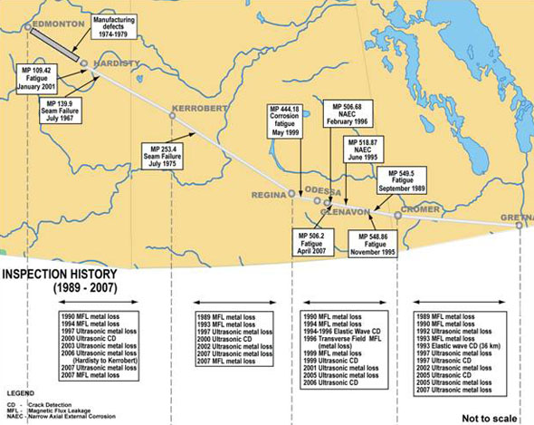
Between 1974 and 1979, five ruptures occurred due to pipe-related manufacturing defects. Two of the ruptures occurred downstream of the Edmonton terminal and three occurred downstream of the Strome pump station. Because these five failures occurred in pipe from the same pipe order (Canadian Phoenix DSAW pipe), Enbridge replaced all Canadian Phoenix DSAW pipe between 1979 and 1985 with IPSCO Inc. DSAW pipe.
In response to a rupture due to corrosion fatigue on Line 3 at Mile Post 549.5 in September 1989, Enbridge committed financial support to the development of an elastic wave tool – an internal inspection device designed to locate and size longitudinal planar defects, such as fatigue cracking, in the vicinity of the longitudinal weld. By 1996, Enbridge had internally inspected most of Line 3 between Regina and Cromer using the elastic wave tool.
Following three ruptures on Line 3 over an eight-month period, the National Energy Board (NEB) issued a directive to Enbridge in March 1996. In response, Enbridge prepared an operational reliability assessment of Line 3 between Edmonton and Gretna and implemented an action plan to address the integrity of the line. The action plan included a hydrostatic test of the line between Odessa and Cromer pump stations, operating pressure reductions, and in-line inspections (ILI) for cracking and narrow axial external corrosion.
Hydrostatic tests conducted in September 1996 consisted of a four-hour strength test followed by a four-hour leak test using water as the test medium for each of the eight sections tested. There were no leaks or ruptures during the hydrostatic tests. The section of pipe that ruptured in April 2007 was included in one of the eight test sections. In October 1996, the NEB approved a maximum operating pressure of 4596 kPa for that section of Line 3.
Over the years, Enbridge has developed a crack management component within its integrity management program to deal with the susceptibility of Line 3 to cracking. Enbridge's crack management plan is aimed at minimizing the possibility of failure due to fatigue cracking of longitudinal weld anomalies and stress corrosion cracking. Monitoring and mitigation strategies include determining the susceptibility to cracking, conducting crack inspections, conducting engineering analyses to estimate remaining life, and determining re-inspection intervals. Crack inspections consist of periodic ILI using a crack detection tool and field digs, both to verify ILI results and to repair injurious anomalies. The program is designed to locate anomalies and to repair those that would affect the safe operation of the line.
In July 1999, Enbridge inspected the Regina-to-Cromer section of Line 3 with an in-line ultrasonic crack detection tool. Enbridge incorporated the results of this ILI into a repair and recoating program. As part of this program, the joint of pipe that failed in April 2007 was excavated in February 2002 and non-destructively tested using magnetic particle and ultrasonic examinations to detect and size cracks along the longitudinal weld. Four anomalies, including the one that failed in April 2007, had been identified on this joint of pipe in the dig information package provided to the field technicians. In 1999, the anomaly that failed was sized at less than 12 per cent in depth and was not identified as requiring immediate attention. However, during the analysis of the ILI data, information from only two of the three ultrasonic crack detection
tool sensors had been used to estimate crack depth. In 2007 following the rupture, the 1999 ILI data was re-analyzed using information from all three sensors. The revised estimated crack depth was 12 to 25 per cent of nominal wall thickness, which would have been flagged for excavation.
Of the four anomalies identified as part of the dig package, only one was noted on the subsequent field report. It was identified as a crack, was removed by grinding, and was then sleeved. The three other anomalies mentioned in the dig information package, including the anomaly that failed in April 2007, were not identified on the field report as having been located or sized.
The other linear indication noted on the field report had not been identified on the ILI report but was located and measured during the non-destructive examination (NDE) of the pipe in the field. It was measured as being 0.4 mm deep, was removed by grinding, and required no further repair. Two other repair sleeves were installed on this joint of pipe in February 2002 to cover areas where cracks had been identified by the 1999 ILI and had been removed by grinding; one sleeve extended over the upstream girth weld and the other sleeve extended over the downstream girth weld.
During the field NDE, the weld cap had been removed from the pipe in the vicinity of the anomalies that were removed by grinding or sleeved, but nowhere else on the pipe joint. Instructions given to the NDE contractor's field personnel were to conduct a magnetic particle inspection of all the longitudinal and girth welds and to specifically look for indications from the ILI tool. Although Enbridge had no written instructions for dealing with false positives, those identified by the ILI tool but not located in the field, it provided verbal instructions to contact Enbridge if indications identified in the dig package could not be found. Following the repairs, the line was recoated with a field-applied epoxy coating and backfilled.
In November 2005, Enbridge made a decision to swap oil streams between Lines 2 and 3. This change in operations resulted in an increase in the total number of pressure cycles as well as an increase in pressure on Line 3 from a maximum of approximately 2758 kPa to a maximum of approximately 4137 kPa. The maximum pressure was below the MOP of 4596 kPa that was approved following the 1996 hydrostatic re-tests. The change in operations resulted in more aggressive pressure fluctuations that Enbridge determined through a fatigue analysis would decrease service life due to an increase in crack growth rates. The analysis indicated that the service life would still be acceptable.
Enbridge established fatigue crack growth rates using fracture mechanics for time-dependent crack growth mechanisms and the analysis procedures of British Standards (BS) BS 7910, the British Standards Institution, titled “Guide on methods for assessing the acceptability of flaws in metallic structures”. Inputs to the fatigue model included an initial flaw size, pressure loading, and fatigue crack growth parameters that depend on pipe material and applied conditions including environment and cyclic frequency.
An ILI using an ultrasonic crack detection tool was again conducted on Line 3 from Regina to Cromer in July 2006. The anomaly that failed in April 2007 was not identified as requiring immediate repair since its depth was in the 12.5 to 25 per cent range and its estimated failure pressure was greater than the hydrostatic test pressure. Enbridge received the 2006 inspection report in the fall 2006 but the field activities both for repair and verification purposes had not yet begun at the time of the 2007 rupture. The verification procedure used by Enbridge was to compare ILI estimated crack sizes, and associated calculated failure pressures, with results obtained in the field by non-destructive ultrasonic inspection or crack grinding, or a combination of the two. Enbridge considers field and ILI data to be sufficiently accurate if the data falls within an error band of plus or minus 10 per cent. Based on 51 features that have been field-assessed to date resulting from the 2006 ILI data, Enbridge has found that the failure pressure ratios calculated from the 2006 ILI results for the Glenavon-to-Cromer section of Line 3 have a 7 per cent non-conservative bias which was not known at the time of the rupture.
Analysis
At the time of construction, the polyethylene tape coating tented over the longitudinal weld, allowing a corrosive environment to contact the pipe wall under the tented coating. When tenting occurs, the polyethylene tape coating shields the pipe from the effects of the cathodic protection system and corrosion can occur. In this case, a narrow corrosion groove formed immediately adjacent to the longitudinal weld under the tented coating.
The corrosion groove provided a stress concentrator, allowing a fatigue crack to initiate due to the pressure cycling associated with normal pipeline operations. Although the epoxy coating applied in the field in February 2002 prevented further corrosion of the crack face, the crack continued to grow by fatigue as a result of continued pressure cycling due to normal pipeline operations.
The extent of corrosion on the crack face provided a measure of crack propagation from the time of crack initiation until the pipe was recoated in 2002. At the time of recoating, a 20-millimetre section of the crack had exceeded 40 per cent of the nominal pipe wall, well in excess of the depth estimated both during the initial analysis and the re-analysis of the 1999 in-line inspection (ILI) data. The re-analysis of the 1999 ILI data shows the extent to which the estimation of crack depth depends on using information from all possible sensors.
During the 2002 field investigation of the ILI indications, magnetic particle examination was used. Magnetic particles can collect in the valley formed between the weld cap and the pipe body. Therefore, at the time of the 2002 field non-destructive examination, it may have been determined that some of the indications from the magnetic particle inspection were a collection of magnetic particles in this valley. Those indications may then have been considered non-injurious weld anomalies. Only by removing this weld cap could it be determined whether or not an indication from a magnetic particle inspection was the result of pooling or indicative of cracking and therefore requiring further testing.
The accuracy of the predictions of the crack growth model depends on the accuracy of the input parameters, including initial crack size. If any of these parameters have been underestimated, actual crack growth rates will exceed predicted values. When the pressure spectrum became more aggressive in November 2005, the input values to the crack growth model did not accurately reflect the uncertainties in measured values and predicted growth was less than actual growth.
The analysis of the 2006 ILI data resulted in the underestimation of the depth of the deepest section of the crack. In addition, there was a non-conservative bias in the failure pressure ratios that had been calculated from the 2006 ILI data. This bias was only evident following field verification of the ILI data and was not known at the time of the rupture.
Enbridge has recognized that Line 3 is susceptible to cracking. Through its crack management program, the company has made significant efforts to ensure that injurious anomalies are detected, evaluated, and repaired. Enbridge has recognized that there is a degree of uncertainty in ILI crack detection tool measurements and has relied on field verification digs to ensure that tool measurements are within an acceptable error band. However, as a result of the February 2002 field inspection, it is apparent that a degree of uncertainty can exist during the non-destructive examination of the pipe in the field.
Findings
Findings as to causes and contributing factors
- The original polyethylene tape coating tented over the longitudinal weld and allowed a corrosive environment to contact the pipe surface immediately adjacent to the weld, resulting in the formation of a shallow corrosion groove along the toe of the weld.
- At some point after the formation of the shallow corrosion groove, a fatigue crack initiated at the corrosion groove as a result of the stress intensity imposed on the pipe by the cyclic stresses resulting from normal pipeline operations.
- The cyclic stresses due to operating pressures allowed the fatigue crack to propagate until the pipe wall was unable to support those pressures and ruptured.
- During the field inspection in February 2002, the weld cap on the longitudinal weld may have masked the identification of the severity of the fatigue crack.
- Although Enbridge recalculated the crack growth rate to reflect the more aggressive pressure regime which began in November 2005, the input parameters used by Enbridge during that analysis did not accurately reflect the actual crack growth rate.
- The analysis of the 2006 in-line inspection data resulted in the underestimation of the depth of the deepest section of the fatigue crack.
Findings as to risk
- Information from only two of three ultrasonic crack detection tool sensors was used in the evaluation of crack depth in the 1999 in-line inspection, resulting in the underestimation of the depth of the fatigue crack.
- The 2006 in-line inspection data showed a non-conservative bias in the failure pressure ratios which affected the identification of potentially injurious anomalies, but was only evident once sufficient information had been provided through the 2007 dig program.
- The depth of short, deep sections of cracks may be underestimated during both the analysis of in-line inspection data and the non-destructive examination of the pipe in the field which would affect the identification of cracks requiring repair.
- When input parameters for the modelling of crack growth rates do not reflect probabilities and tolerances associated with the detection and sizing capabilities of ILI ultrasonic crack detection tools as well as actual pipe conditions, actual crack growth rates may exceed estimated values.
Safety action
Safety action taken
Following this rupture, Enbridge has:
- implemented an 80 per cent pressure restriction on the discharge pressures at Regina, Odessa, Glenavon, and Langbank pump stations and agreed to maintain this restriction until Line 3 has been inspected for cracking and a repair program has been completed;
- completed piping changes at Cromer terminal to reduce the number of pressure cycles that occurred upstream of Cromer;
- conducted full-scale, pressured-pipe fatigue tests on pipe which contained crack defects similar to the fatigue crack that failed in April 2007 and was cut out from Line 3 to better estimate parameters used in its crack growth model;
- commissioned a study to establish a method for selecting a conservative initial crack depth from in-line inspection data, taking into consideration the uncertainty associated with the data;
- re-analyzed the 2006 in-line inspection data and identified an additional 96 features to be included with the 2008 dig program to account for the non-conservative bias in the data; and
- made several changes to its Line 3 crack management program, including: a revised schedule of in-line inspection; revisions to fatigue analysis procedures, modifications to crack repair criteria, changes to field inspection and repair activities, improvements to pressure cycle monitoring activities, and continued support for in-line inspection crack tool developments.
Prior to the rupture on 15 April 2007, the National Energy Board was developing a plan to audit the integrity management program for Enbridge's facilities. Following the rupture, the National Energy Board expanded the scope of the audit to include the integrity management program for the entire Enbridge pipeline system within Canada.
This report concludes the Transportation Safety Board's investigation into this occurrence. Consequently, the Board authorized the release of this report on 16 July 2008.
Appendices
Appendix A – Long seam failures on Line 3