
Aviation Investigation Report A10P0242
Loss of Engine Power and Landing Rollover
Transwest Helicopters Ltd.
Bell 214B-1 (Helicopter), C-GTWV
Lillooet, British Columbia, 20 nm NW
The Transportation Safety Board of Canada (TSB) investigated this occurrence for the purpose of advancing transportation safety. It is not the function of the Board to assign fault or determine civil or criminal liability. This report is not created for use in the context of legal, disciplinary or other proceedings. See Ownership and use of content.
-
Table of contents
Summary
The Transwest Helicopters Ltd. Bell 214B-1 helicopter (registration C-GTWV, serial number 28048), with 2 pilots onboard, was engaged in firefighting operations approximately 20 nautical miles northwest of Lillooet, British Columbia. At 1124 Pacific Daylight Time, after refilling the water bucket, the helicopter was on approach to its target near a creek valley. As the helicopter slowed and started to descend past a ridgeline into the creek valley, the engine lost power. The pilot-in-command, seated in the left-hand seat, immediately turned the helicopter left to climb back over the ridgeline to get to a clearing, released the water bucket and the 130-foot long-line from the belly hook, and descended toward an open area to land. The helicopter touched down hard on uneven, sloping terrain, and pitched over the nose. When the advancing main-rotor blade contacted the ground, the airframe was in a near-vertical, nose-down attitude, which then rotated the fuselage, causing it to land on the left side. A small post-crash fire ignited. The pilot-in-command sustained a concussion and was rendered unconscious. The copilot escaped with minor injuries and dragged the pilot-in-command from the wreckage. The pilot-in-command regained consciousness a few minutes later. The helicopter was substantially damaged. The 406-megahertz emergency locator transmitter was activated, but its antenna fitting fractured; as a result, the search and rescue satellite network did not receive a signal.
Factual information
History of the flight
The day before the accident, the occurrence helicopter's engine fuel control unit (FCU) was replaced due to reported abnormal and excessive droopFootnote 1 in the main-rotor revolutions per minute (rpm). The helicopter subsequently flew 8.0 hours without incident, with the occurrence pilots reporting that the rpm droop condition was less pronounced than it had been before the FCU was replaced. On the day of the occurrence, the helicopter was refuelled and took off at about 1000.Footnote 2
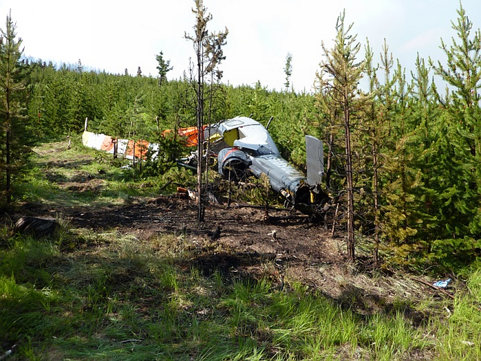
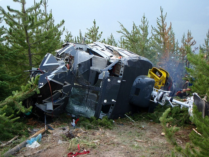
During the occurrence flight, the pilots successfully carried out 12 water-drops. While the pilot-in-command (PIC) was preparing to drop another load of water, at an altitude of approximately 200 feet above ground level (agl) and 20 knots indicated airspeed, the engine lost power. The loss of power led to a rapid decay in main-rotor rpm and triggered the low-rotor rpm and engine-out warning lights and the aural alarm. The PIC climbed the helicopter over the ridgeline to return to a clearing the helicopter had just passed, lowered the collective to reduce the power demand, turned left, released the water bucket and the 130-foot long-line from the belly hook, and descended toward a clear area below. Due to the helicopter's proximity to the ground when the power loss occurred, the pilots did not have time to attempt a switchover from automatic fuel-mode to manual fuel-mode.Footnote 3 As the helicopter neared the ground, the PIC adopted a near-level flight attitude and applied full collective to cushion the landing. Due to the uneven terrain and forward momentum of the helicopter, the advancing main-rotor blade contacted the ground on the right side, and the airframe was in a near-vertical, nose-down attitude. The helicopter rotated over the nose and came to rest on its left side, facing uphill (photo 1 and photo 2). The tailboom broke off at the elevator-horn section, and the tail-rotor assembly landed 30 feet away. The engine continued to run at reduced rpm until the copilot shut it down. The PIC was rendered unconscious, while the copilot escaped with minor injuries. The copilot got into the left side of the cockpit through the left-hand cabin-roof window (by kicking out the window), and dragged the PIC from the wreckage.
Following the impact, a small oil fire ignited in an exhaust duct, which started a brush fire near the helicopter. The copilot extinguished the oil fire in the exhaust duct, using a handheld fire extinguisher. The brush fire was extinguished by other firefighting helicopters operating in the area.
The accident site was located at 50º53'45" N, 122º17'21" W, 5800 feet above sea level.
The helicopter was retrieved from the accident site and transported to the Transwest Helicopters Ltd. (TWH) facility in Chilliwack, British Columbia.
Weather
Weather conditions were suitable for flight in accordance with visual flight rules, and were not a factor in the occurrence.
Pilots
Records indicate that the pilots were certified and qualified for the flight in accordance with existing regulations. The PIC held a valid airline transport pilot licence (helicopter), and had worked for the operator in the heli-logging/firefighting role for 13 years. The PIC had accumulated about 26 000 flight hours in total, with at least 11 000 flight hours on type, and about 14 000 flight hours in vertical-reference external-load operations.Footnote 4
The copilot held a valid commercial pilot licence (helicopter) and had accumulated about 120 hours of flight experience, all in helicopters. The copilot was new to helicopter firefighting operations, and had worked for the operator for about 1 week. The copilot's functions were to record times, weights, and engine-performance data; to act as a safety pilot; and to accumulate flight experience.
The flight crew's flight- and duty-time limitations were not exceeded, and there was no indication that physiological factors, such as fatigue, affected the flight crew's performance.
The helicopter
Manufactured in 1980, the Bell 214B-1 helicopter is a single-engine, 2-bladed helicopter. The occurrence helicopter was equipped with a 2930 shaft horsepower (SHP) HoneywellFootnote 5 T5508D free-power turbine engine (serial number [SN] LE31953), with a maximum delivery to the main-rotor gearbox of 2050 SHP. Records indicate that the helicopter was certificated, equipped, and maintained in accordance with existing regulations and approved procedures. At the time of the accident, it had accumulated about 15 810 hours of service.
The helicopter was equipped with a Hamilton Sundstrand FCU (model JFC31-20, part number [PN] 2-160-620-22, SN 86667). The FCU had been installed the day before the occurrence, replacing FCU PN 2-160-620-22, SN 86675.
At the time of the occurrence, the helicopter had about 500 pounds of fuel remaining. Post-occurrence calculations showed that the weight of the helicopter, including the loaded Bambi (water) bucket, was about 14 500 pounds at the time of the occurrence. The helicopter was within the weight limits and center-of-gravity limits for external-load flight operations.
Crashworthiness and survivability
The forces induced by the yaw at impact contributed to the nature of the injuries. Both pilots were wearing helmets. During the impact and subsequent rollover, the right side of the helmet of the PIC in the left-hand seat hit the forward door frame; the PIC sustained acceleration–deceleration injuries to the head and neck as a result.

Both pilots wore the lap-belt portions of the restraint system. The PIC did not use the shoulder harness, because it prevented an adequate view of the load through the bubble window; the copilot chose not to wear the shoulder harness for reasons of comfort. Had the pilots worn the available shoulder harnesses, their body movements would have been more restrained.Footnote 6 A recent National Transportation Safety Board (NTSB) safety study concluded that use of both a lap belt and shoulder harness consistently reduces the risk of pilot fatality or serious injury when compared with use of a lap belt alone.Footnote 7 The analysis, which included over 37 000 single-engine airplane accidents that occurred between 1983 and 2008, determined that the risk of fatal or serious injury with use of a lap belt alone was nearly 50% greater than with use of a lap belt and shoulder harness combined. These findings are consistent with a 1985 safety study also conducted by the NTSB.Footnote 8
Engine
The engine was removed from the airframe and inspected. While it could not be run in a test cell due to damage from the accident, disassembly of the engine core did not reveal any direct mechanical reason for the loss of engine power.
Components of the engine fuel system were removed, examined and tested. These components included the overspeed valve and the fuel-flow divider; all performed as expected. All associated fuel lines and fittings were removed, inspected and tested. None of the examinations or tests of the components revealed a cause for the loss of power event. The wiring of the airframe to the engine overspeed protection system (O/S) was verified, and the system circuit breaker was found in the pulled position. The investigation determined that TWH pilots believed that the O/S caused inadvertent engine shut-downs in the Bell 214-B1 model and was normally disabled by company pilots pulling the electrical-protection circuit breaker to this system.
Fuel control unit
The FCU had accumulated a time since overhaul (TSO) of approximately 1546 hours. The FCU was sent by the Transportation Safety Board (TSB) to a Transport Canada (TC)−approved Honeywell Aerospatiale component repair and overhaul facility (a subsidiary of Honeywell USA) at Summerside, Prince Edward Island (HON PEI). A detailed receiving inspection and functional test were performed on the FCU, with the TSB and the operator's representative in attendance. While the FCU failed to meet several run-as-received test points and demonstrated an air-bleed anomaly that could be adjusted, no cause for the loss of power could be inferred from or explained by the results of the functional test.
Engine test-cell run
The FCU was later installed on a Honeywell T5508D engine in a test cell at the TWH facility in Chilliwack. The engine test cell uses a water-brake system to simulate the load applied to the engine through the main-rotor gearbox. During initial test runs of the engine, overspeed trip-protection system of the engine test cell operated inadvertently, causing the engine to decelerate to flight idle; a faulty test-cell valve was replaced for subsequent testing. The power turbine section (N2) of the engine drives the main-rotor gearbox; when the main-rotor rpm (NR) is at 100%, the specified engine N2 rpm equals 96.2%. In the subsequent test, fuel flow was set to specify 1480 pounds per hour, and loading of the engine was increased to verify the capability of the engine to deliver 2050 SHP. Results showed that, with the occurrence FCU installed, the engine was capable of delivering close to 120% indicated aircraft torque, or nearly 300 SHP above that specified. To maintain 100% NR, the N2 rpm indicated 95.5%, and 94.3% N1 compressor speed.
Teardown examination of the fuel control unit
The FCU was bench-tested and examined by Hamilton Sundstrand at its facility in the Netherlands. These tests produced results similar to those obtained at HON PEI. The FCU was then completely disassembled, and several components were taken to the TSB Laboratory in Ottawa for metallurgical examination.
During disassembly of the FCU in the Netherlands, it was noted that the FCU did not conform to the configuration for a -22–modified FCU. The -22–modified FCU embodies several proprietary modifications that extend the time between overhaul (TBO) from 1800 hours to 2400 hours.
In addition, 5 relatively large fragments were found in the FCU:
- A cotter pinFootnote 9 leg from the linkage-position adjustment group (Photo 4), that had broken off before the occurrence due to fatigue, caused by rubbing. The cotter pin is located next to the ratio servo flapper-valve. The fatigue fracture was caused by the contact and mutual movement of the cotter pin and the speed-adjustment lever. Unlike references to other cotter-pin installations in the linkage housing section of the FCU, Figure 5-13 and instruction 5-14.b of the Hamilton Sundstrand Component Maintenance Manual (CMM) F3120 do not refer to a washer at that location, and none was installed. The absence of a washer is inconsistent with standard practice for this type of application. A washer is normally installed to reduce the risk of fatigue failure due to rubbing.Footnote 10
- A fragment fractured from the flange of the N1 servo-valve sleeve (Photo 5). The initial crack in the flange pre-dated the occurrence, and the separation of the fragment likely also happened before the occurrence. In 1985, Hamilton Sundstrand issued a service bulletin (SB) intended to provide servo-valve sleeve-retention slots with improved durability.Footnote 11 Only the N2 servo-valve had been modified in accordance with this SB. The modification had not been applied to the N1 servo-valve. This SB also applies to the following other aircraft types, all of which utilize similar valves:
- Bombardier Challenger CL-600 (Avco Lycoming ALF 502L turbofans)
- Chinook CH-47A helicopter (Lycoming T55 turboshaft engines)
- British Aerospace BAE 146 (Lycoming ALF 502 geared turbofan engines, subsequently replaced by the higher-thrust derivative Honeywell LF 507 geared turbofan engines with the development of the Avro RJ-series aircraft)
- Three stainless steel tabs of unidentified origin were also found in the FCU cavities and passages, where they were free to circulate.


All 5 fragments listed above were at least 1 dimension larger than 1 mm, and any one of them could have either temporarily obstructed fuel flow through some of the passages or impeded the normal operation of some valves. While metal fragments and non-metallic debris were also found on several filters, their presence would not have impeded fuel flow so as to result in a loss of power.
While signs of wear were found on other parts of the FCU, they were not considered causal or contributory to this occurrence.
Fuel-control-unit drooping issues vs. time-between-overhaul expectation
In consultation with the FCU manufacturer and engine manufacturer, the TSB (LP 018/2011) examined previous reports of loss of power and drooping of the main-rotor rpm on the Bell 214B-1. It was determined that Bell 214B-1 FCUs were often sent for repair and/or overhaul before the expected TBO of 1800 hours. From 2004 to 2010, 51 units were returned for repair and/or overhaul. Of those 51 units, only 11 units had TSO indicated. Nine of those units were returned before the TBO of 1800 hours, with an average TSO of 1006 hours. This information did not trigger any mandatory compliance directive from Honeywell or from the original equipment manufacturer, Hamilton Sundstrand.
Also, a review of the available data determined that the source of the loss of power and excessive droop was most likely associated with the inability of the FCU to compensate for and/or anticipate an increased load placed on the engine by the main rotor. In many cases, units that required unscheduled maintenance due to excessive droop could be recalibrated to meet the return-to-service criteria defined by the component maintenance manual.
TWH operations of the Bell 214B-1 were considered normal for power-plant use, and were conducted in normal environmental conditions with clean, recommended fuels. The FCU in this occurrence had accumulated a TSO of 1546.4 hours. The FCU that it had replaced had a TSO of 1161.3 hours when it was removed due to excessive droop.
Fuel-cam wear
According to Hamilton Sundstrand, wear to the contours of the 3D camFootnote 12 beyond the limits specified in the CMM may result in fuel-scheduling anomalies. During the disassembly of the occurrence FCU at the manufacturer's facility, a wear groove reported as unusual was observed on the 3D cam (Photo 6). However, no previous fuel-scheduling anomalies had been reported or recorded in the journey log of the occurrence helicopter. As a result, the 3D cam was sent to the TSB Laboratory, where it could be evaluated for its possible contribution to the power loss experienced during the occurrence. Testing conducted by the TSB Laboratory determined that the wear was within the limits specified by the manufacturer. This type of wear was indicative of solid-to-solid wear interaction between the 3D cam and the cam follower surfaces, and indicated that small metal particles were being removed from the contact surfaces of the cam and the followers.

Overhaul quality control
Honeywell facilities repair and overhaul FCUs and other fuel-system components. The company's USA facilities were not required to have a safety management system (SMS). In Canada, an approved maintenance organization (AMO) is required to have a SMS if it includes ratings for aircraft types that would be subject to subpart 705 of the Canadian Aviation Regulations if operated for commercial air transport., At Honeywell's PEI facility, a SMS was in place for components used by 705 operators, but not for those used by 703 operations like TWH.
Hamilton Sundstrand CMM F3120 provides instructions for overhaul of the FCU.Footnote 13 However, paragraph 5-1(b) states that “only those steps that are necessary for adequate inspection and repair of the affected items need be performed.” Honeywell and HON PEI interpreted this statement to mean that, in the absence of any other instructions for continued airworthiness, technicians can determine whether to perform the inspection without disassembling the associated subcomponents of the FCU. TC provides a definition of “overhaul”,Footnote 14 but does not define the level of overhaul instruction; it is up to the original equipment manufacturer of the product to recommend the scope and detail of the work required.
The investigation also determined that HON PEI does not maintain a specific record or detailed check sheets to indicate all of the tasks that were performed during overhaul. A process and test document indicated that the FCU was disassembled. However, the document did not address each disassembly task, and it made no reference to the cotter pin, which (according to paragraph 5-14 of CMM F3120) must be replaced if it is removed. According to the interpretation by Honeywell and HON PEI of CMM F3120, if the decision is made, based on paragraph 5-1, that further disassembly is not required to inspect the subcomponents, there is no need to remove and replace the cotter pin as outlined in paragraph 5-14. However, the manual also stipulates (in Section 3, paragraph 5-25[a] of CMM F3120) that the technician “inspect all parts for wear, galling, metal pickup, cracks, nicks, burrs, dents, and other damage. Pay particular attention to mating surfaces.” It also specifies, in paragraph 5-26,Footnote 15 detailed inspection requirements after cleaning, including visual inspection for thread damage of the clevis nut at the N2 linkage-position adjustment group. Additionally, complete disassembly would be required to inspect the straight-headed pin (PN 577896-6) or the clevis nut (PN 588326). Honeywell advised that HON PEI inspects the clevis nut by removing the mating adjustment screw to access and inspect the threads.
The investigation determined that HON PEI believed that a FCU could be designated as a ‑22 configuration if the unit were overhauled in accordance with CMM F3120 and incorporated the instructions associated with SB 5508-0029. HON PEI reached this decision following a review of SB 5508-0029. HON PEI did not have access to the vendor's manual, which contained detailed instructions for modifying the FCU to a -22 configuration, because the vendor's manual was proprietary to Hamilton Sundstrand. Therefore, several product-improvement modifications were not incorporated, and the occurrence FCU was misidentified as a -22 configuration. It wasn't until after the occurrence that Honeywell identified, during an internal audit, that 16 FCUs overhauled by the HON PEI facility had been incorrectly identified as PN 2-160-620-22. (See Safety Action Taken.)
The TSB Laboratory completed the following reports:
- LP 114/2010 – GPS Data Retrieval
- LP 149/2010 – Metallurgical Examination of Component Parts of FCU
- LP 018/2011 – FCU Failure Analysis
These reports are available from the TSB on request.
Analysis
The occurrence helicopter experienced a loss of power in a critical phase of flight, while the pilot was preparing to drop a load of water. In response to the power loss, the pilots identified a nearby landing area and carried out an emergency landing. However, the nature and slope of the terrain in the touchdown area caused the helicopter to roll over after touchdown. The combination of low airspeed, high-density altitude,Footnote 16 height above ground at the time of the power loss, gross weight of the helicopter, and nature and slope of the terrain precluded an uneventful landing.
The rest of the analysis section will focus on the factors which may have led to the power loss, as well as on the fuel control unit (FCU) overhaul procedures in place at the time of the occurrence.
Examination during disassembly of the FCU found several fragments of metallic debris, including a broken cotter-pin leg, that could temporarily obstruct fuel flow through some of the passages or impede normal operation of some valves. This cotter pin is normally located next to the ratio servo flapper-valve, and the separated leg could have obstructed the valve's operation. The FCU was also contaminated with other metallic debris, which could have disrupted fuel flow and caused the engine to lose power. Given the absence of any other pre-existing condition or helicopter system malfunction, this contamination with metal debris likely caused the FCU to malfunction and the engine to lose power.
The investigation determined that the cotter pin from the N2 linkage-position adjustment group broke as a result of a fatigue fracture caused by contact with and mutual movementof the speed adjustment lever. According to Figure 5-13 and instruction 5-14.b of component maintenance manual F3120, installation of a washer at the cotter-pin location of the N2 linkage-position adjustment group was not required. This lack of requirement is inconsistent with standard practice for similar applications, where relative or mutual movement of parts can cause wear, generate debris, and ultimately result in fractures. As a result, there was increased risk of fatigue failure during flight operations.
There were no detailed records of the tasks completed during the overhaul process. Without a record of all completed tasks, quality assurance cannot be checked, and risk managers lack valuable information. The investigation determined that the FCU was not completely disassembled and that all of the cotter pins may not have been replaced. Complete disassembly would have allowed for better inspection of all subcomponent parts and possible identification of the wear condition. It would also have required the replacement of the cotter pin, thereby reducing the cotter pin's susceptibility to failure. In addition, detailed records of parts replaced would help detect reliability issues, which could have an impact on continued time in service. If the FCU is not completely disassembled during overhaul, there is increased risk that damage to subcomponents will go undetected.
The investigation also determined that the occurrence FCU had been wrongly designated by Honeywell Prince Edward Island (HON PEI) as a -22 configuration. HON PEI misinterpreted documentation, and concluded that its facility was able to carry out the modifications that were necessary to identify FCUs as -22 units. However, HON PEI did not have access to all of the necessary documentation from the vendor. This lack of documentation led to omissions in the overhaul and modification of the FCU and in the applicable service bulletin (SB) for the -22 conversion. The outcome was that the FCUs designated as -22 units had a time between overhaul (TBO) of 2400 hours, although all of the modifications to support that extended life were not completed. Therefore, these FCUs were at increased risk for failure prior to removal.
The subject-model FCUs were often sent for repair and recalibrated because of loss of power or drooping issues before the expected TBO (see Fuel-control-unit Drooping Issues vs. Time-between-overhaul Expectation). These issues were occurring on non-modified and misidentified -22 FCUs. In this instance, both the occurrence FCU and the FCU that it replaced failed before 1800 hours of time since overhaul (TSO). The high number of FCUs removed from service before 1800 hours of TSO did not trigger any follow-up action by Honeywell or HON PEI, or by Hamilton Sundstrand. Reliability data was not collected by the operator, the engine manufacturer, the component manufacturer, or the repair-and-overhaul facility. Monitoring performance is a key element of safety management systems. Without performance monitoring , there is increased risk that problems associated with the reliability of these components will go undetected.
The FCU's N1 servo-valve sleeve had a fractured retention slot/flange. This type of servo valve is also used on other aircraft types. Therefore, if SB JFC31 No. 3012 is not applied to other aircraft types that utilize similar fuel-control servo-valve sleeves, those aircraft may be at risk for similar fractures.
It is common for pilots engaged in vertical-reference long-line operations not to use available upper-body restraint systems, because it restricts their movement and prevents them from positioning themselves in ways that allow a vertical view of the external load. In this occurrence, the pilots were wearing helmets. The use of helmets likely prevented head injuries during the occurrence. However, the pilots were wearing only lap-belts and suffered minor injuries when the helicopter rolled over. If available shoulder restraints are not worn, there is increased risk of injury following a non-normal landing event.
Findings
Findings as to causes and contributing factors
- The engine fuel control unit was contaminated with metallic debris that likely disrupted fuel flow and caused the engine to lose power.
- The nature and slope of the terrain in the touchdown area caused the helicopter to roll over during the emergency landing.
- In circumstances where contact between parts results in relative and mutual movement, there is a risk that this can cause wear, generate debris, and ultimately result in fractures.
- If overhaul procedures and documentation are not clear and detailed, there is increased risk that an impending failure of a component or one of its subcomponents will go undetected and the component or sub-component will be returned to service.
- If recurring component failures are not tracked and monitored, there is increased risk that problems associated with the reliability of components will go undetected.
- Special Bulletin JFC31 No. 3012 was not incorporated completely, and this bulletin applies to several other aircraft types. Without thorough application of the bulletin, other aircraft are at risk for similar fractures.
- If the available shoulder restraints are not worn, there is increased risk of injury during an accident.
Other findings
- The fuel control unit was designated as a -22 configuration with a time between overhaul of 2400 hours; however, it did not have the required modifications. Sixteen additional fuel control units were similarly misidentified.
- Transport Canada provides the regulatory framework to original equipment manufacturers for the development of instructions for continued airworthiness, but does not define the level of overhaul instruction. In this occurrence, the manufacturer's instructions for continued airworthiness were interpreted to allow for overhaul without complete disassembly of subcomponent parts of the fuel control unit.
- Both pilots were wearing helmets. The pilot-in-command suffered head and neck injuries during the impact and subsequent rollover.
- The investigation could not establish whether wear of the components of the fuel control unit contributed to the power loss and drooping issues reported on this model of fuel control unit, or whether the power loss and drooping issues were related to sending these fuel control units for repair before the expected time between overhaul.
- Company pilots regularly disabled the engine's overspeed protection system in the Bell 214-B1 model helicopter, and by doing so, removed an engine protection system.
Safety action
Safety action taken
Transwest Helicopters Limited
As a result of the findings of the initial-stage investigation into this accident involving a Bell 214B-1, Transwest Helicopters Ltd. has reduced the time between overhaul (TBO) of all fuel control units (FCUs), including those with -22 configuration, to 1800 hours.
Honeywell USA
Shortly after the occurrence, Honeywell became aware that a cotter-pin leg had been found in the occurrence FCU, and the company began its root-cause corrective action process. In addition, Honeywell became aware that the occurrence FCU had been incorrectly identified as a -22 configuration.
As part of the root-cause corrective action process, Honeywell conducted an audit of the HON PEI facility to identify the conditions (i.e., physical, administrative, policy, process, etc., or human factors) that allowed the FCU to be misidentified and the required modifications not to be incorporated.
On 13 December 2010, Honeywell issued Service Bulletin (SB) T5508D-047, Engine – Fuel System – Incorrectly Identified Fuel Control Part No. 2-160-620-22, to address the fuel-control-unit configuration issue. The SB reduced the TBO to 1800 hours.
On 26 October 2011, Honeywell issued an Alert Category 1, Safety Service Bulletin: T5508D-A0048, Engine − Fuel System − Incorrectly Maintained Fuel Controls. This SB highlighted the fact that some FCUs were not always completely disassembled for inspection (including those that were converted to the PN 2-160-620-22 configuration). The SB provided the following warning:
Failure to comply with this service bulletin could cause disruption of fuel control operation and a corresponding loss of, or reduction in, engine power and serious injury or death to personnel and damage to, or loss of, the aircraft.
The SB also identified a number of affected units and provided the following instructions:
These controls must be removed from service and returned to Hamilton Sundstrand for overhaul in accordance with the applicable Hamilton Sundstrand technical documentation or continuing airworthiness instructions. Units that were not converted to the -22 configuration may be returned to the Honeywell Prince Edward Island repair station for overhaul.
This report concludes the Transportation Safety Board's investigation into this occurrence. Consequently, the Board authorized the release of this report on . It was officially released on .