
Aviation Investigation Report A02P0320
Loss of Engine Power / Collision with Tree
Hayes Helicopter Services Limited
Sikorsky S-61N (Shortsky) Helicopter C-FHHD
Lake Errock, British Columbia
The Transportation Safety Board of Canada (TSB) investigated this occurrence for the purpose of advancing transportation safety. It is not the function of the Board to assign fault or determine civil or criminal liability. This report is not created for use in the context of legal, disciplinary or other proceedings. See Ownership and use of content.
-
Table of contents
Summary
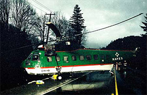
At about 1200 Pacific standard time, the Sikorsky S-61N helicopter, C-FHHD, serial number 61490, took off from the service landing area near Lake Errock, British Columbia, with two pilots and an aircraft maintenance engineer on board to carry out performance adjustments to the engines. Two minutes later, while the helicopter was climbing through about 1000 feet above sea level (asl) at about 65 knots, the crew became aware of an intensifying whining sound which was followed by a single, loud bang. Immediately the number 1 engine lost power and the number 2 engine did not automatically compensate for the power loss.
The pilot-in-command (PIC) lowered the collective lever to enter autorotation and pushed the cyclic stick forward. Acrid smoke filled the cockpit, and flames appeared from the lower left section of the main rotor gearbox in the cabin. The PIC manoeuvred the helicopter for a southwest autorotative landing on a vacant and straight segment of Highway 7 near the Lake Errock village. During the last seconds before touchdown, the pilots saw powerlines across the road, and the PIC increased the collective to reduce the descent to avoid them. The helicopter was landed on the road at about 20 knots ground speed and the wheel brakes were applied. During the roll-out, the helicopter struck other powerlines across the road, and the main rotor blades severed a large tree on the left side of the road. The helicopter veered right and the tail rotor and tail pylon struck the same tree and broke away from the fuselage. The helicopter then started to vibrate severely, with large airframe oscillations, but it remained upright and stopped at the right-hand edge of the road. The three occupants received minor injuries, and the helicopter was substantially damaged. The in-flight fire in the cabin roof was brief and localised, and it self-extinguished.
Factual information
Pilots
The pilots were trained and licensed appropriately for the helicopter and the mission. They were each experienced and qualified heli-logging pilots and had worked for the operator for several years.
Both pilots were wearing seat lap-belts and protective helmets, however, neither was wearing the available shoulder harness. Their helmets sustained damage from multiple strikes with the cockpit interior during the oscillations on the ground that likely would have caused serious injuries to an unprotected head. The aircraft maintenance engineer was not seated and was injured as a result of repeated contact with the interior cabin structure near the cockpit entry.
General Information
No formal weather observation exists for the area of the accident; however, the general weather conditions were an overcast sky with fog patches and light wind.
A review of the aircraft technical logs indicates that the helicopter was certificated and maintained according to the required Transport Canada (TC) standards.
After the accident, the two fuel gauges on the cockpit instrument panel each showed a fuel quantity of about 1000 pounds. Given that the flight lasted only two minutes, the helicopter took off with a total fuel quantity in the order of 2100 pounds. Fuel samples were examined from the refuelling source, the helicopter tanks, and all the engine fuel control components. As a result of these tests, it was concluded that the fuel on-board the helicopter at the time of the accident was not contaminated and was not a factor in the accident.
Using the most recent weight and balance records, it was determined that the helicopter was about 13 300 pounds at take-off with a centre of gravity (CG)about 270 inches aft of the datum. The maximum allowable weight of the helicopter is 22 000 pounds with a CG range of 258 to 276 inches aft of the datum.
Sikorsky S-61N C-FHHD
C-FHHD was owned and operated by Hayes Helicopter Services Limited of Duncan, British Columbia (B.C.), and was principally engaged in heli-logging activities in B.C. The helicopter was originally manufactured by Sikorsky Aircraft in 1971, and was later modified by Heli-Pro Corporation in March 1996 to the shorter, civilian Shortsky model, similar in size to the military SH-3 "Sea King" helicopter. Sikorsky Aircraft Design Engineering was not involved in the modification, and Hel-Pro Corporation was not Sikorsky-approved. The modification was not approved by Sikorsky; however, it was approved by Transport Canada (TC). The helicopter is equipped with two General Electric Aircraft Engines (GEAE) model CT58-140-1 gas-turbine engines. At the time of the accident, the helicopter had accumulated about 30 323 hours total flight time as both original and modified airframes.
Main Rotor Gearbox
The main rotor gearbox (MGB) had been most recently overhauled by the TC-approved Hayes overhaul facility in Duncan and was installed in C-FHHD on 29 September 2002. At the time of the accident, it had accumulated 361 hours in service since overhaul, for a total service life of 27 220 hours. Following the accident, the MGB was removed from the airframe and inspected, disassembled, and examined at a TC-approved overhaul facility in Richmond, B.C., under the direct supervision of TSB investigators.
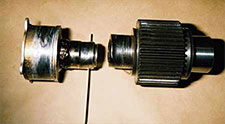
The MGB attachment fittings on the fuselage were intact. The MGB was undamaged, with the exception of the Number 1 (left)Footnote 1 input pinion gear (Photo 2) which had fractured just forward of the forward bearing journal, and its associated forward plain bearing (located in the MGB cover) which had mostly disintegrated. The splined coupling showed severe rub on the gimbal ring.
Number 1 Input Pinion Gear
Once the number 1 plain bearing began to fail, the adjacent carbon seal broke down, allowing oil to spray out from the MGB. Without sufficient lubricant, the number 1 pinion rapidly overheated and weakened, leading to thermal distress, distortion, and subsequent fracture. The pinion fracture surface exhibits equiaxed ductile dimples, indicating tensile or bending overload, rather than torsional overload. Accordingly, the torque on the pinion was low when it broke. While components adjacent to the fracture were covered with soot, oil, and grease, the fracture surface itself was free of contamination, which may indicate that the break occurred after the grease and oil sprayed from the damaged bearing and coupling, and after the fire.
Dimensional examinations revealed about four degrees of bend on the pinion and about four degrees of bend in the high-speed shaft. By design, the splined coupling accommodates about four degrees of deflection before either the high-speed shaft or the pinion starts to bend. As well, the forward end of the shaft exhibits damage that occurred when the forward flexible coupling was bent beyond normal limits, and while the shaft was still rotating. Theoretically, it is likely that about eight degrees of misalignment existed, and likely less since the deviation was a dynamic whirl, not static bending. Such misalignment may have been possible with intact engine mounts and MGB attachment fittings.
Structural analyses of the stresses present at the fracture site revealed that the initial effect of lubricant loss was severe and rapid friction wear between the pinion gear and the bearing. As the wear progressed, the gear radially displaced from the centerline of rotation, allowing the entire shaft assembly to orbit, creating a centrifugal load imbalance that would have been manifest as a high-frequency vibration. The imbalance would have also created a remarkable bending load on the components, forming the highest stress at the fracture point on the pinion. Calculations showed that such centrifugal forces can create bending loads that exceed the ultimate tensile strength of the pinion with about three degrees of coupling misalignment. Since the pinion was subjected to thermal distress as well, the ultimate tensile strength would have been reduced, and the misalignment required to fail the component would have been proportionally less. Given this situation, it could be said that the misalignment could have occurred with intact engine mounts; although a possibility, there is insufficient information to be conclusive.
Input Freewheel Units
The input freewheel units (IFWU) were installed in the MGB on 26 November 2002 at 30 303 airframe hours, and each had accumulated 20 hours in service at the time of the accident. The IFWUs demonstrated normal wear with no evidence of slip or spit-out. There are, however, inconclusive marks of skidding on roller G on the number 1 IFWU. Damage to such specific areas can indicate IFWU slip or roller spit-out; absence of such evidence is not conclusive that slip or spit-out did not occur. As well, a small amount of fine debris from the disintegrated plain bearing was found in both IFWUs; such contamination can cause IFWU slip.
Rotor Blades
The main- and tail-rotor blades exhibited damage patterns and overload fractures that are consistent with considerable rotor rpm at impact with an object, and characteristic of blades that were not being driven at impact. One main rotor blade fractured about four feet from the blade root, and other pieces of the main rotor blades were found several hundred feet away. Such blade damage caused massive main rotor dynamic imbalance and led to the severe vibration and airframe oscillations experienced on the ground.
CT58-140-1 Engines - General
The two gas-turbine engines are the GEAE CT58-140-1 model, serial numbers 280309KL (Number 1) and 280324KL (Number 2). The number 1 engine was installed in C-FHHD on 12 August 2002 at 29 571 airframe hours, with 998 hours since major overhaul; at the time of the accident it had accumulated another 752 hours, for a total time of 1750 hours since overhaul. The number 2 engine was installed in C-FHHD on 27 November 2002 at 30 303 airframe hours with zero hours since major overhaul; at the time of the accident it had accumulated 20 hours total time since overhaul. Both engines had been most recently overhauled by TC-approved Aero Turbine Support Limited (ATS) of Richmond, B.C.
Both engines were taken to the TSB regional wreckage examination facility in Richmond and inspected, disassembled, and examined in detail. In summary, the examinations of the two engines revealed several anomalies, as described in the following paragraphs.
The CT58-140-1 engine is equipped with an overspeed shutoff valve that by design interrupts the fuel flow in the fuel control unit (FCU) in the event of a free power turbine overspeed. Activation of this overspeed protection does not leave any mechanical indication that the engine shut down, and it could not be determined if an overspeed shutdown occurred in either engine. The overspeed shutoff valve closes when the power turbine speed exceeds 23 400 rpm (123%Nf) . The valve re-opens when the turbine speed reduces, and introduces fuel into the combustion chamber. Since the engine does not have re-ignition, the fuel will not ignite, and as a result, the combustion area can become wet with the unburnt fuel. Such fuel wetting or staining in the combustion section of the engine may indicate an overspeed shut down from a high power setting. In this installation, the engine speed reached when the overspeed protection functions is such that no dimensional or metallurgical changes to the power turbine would be expected to occur. Dimensional and metallurgical examinationsFootnote 2 of the 1st stage turbine rotor disc and the power turbine rotor disc, of both engines, revealed no indication of either overspeed or over-temperature conditions.
According to the engine manufacturer, GEAE, the T58-GE-5 military engine can be converted to the commercial variant CT58-140 provided the "Special Workscope for Conversion of T58 Engines to CT58-140" is complied with. In part, the workscope (item 7) prescribes the following "Replace nameplate and mark with CT58 engine model. Use the same engine serial number and mark with an "R" after the serial number to indicate the engine is converted." The serial number on the nameplates (dataplates) on these two engines had not been so marked.
Furthermore, GEAE advises that the use of military parts on commercial engines is not recommended; however, using the military power section assembly is acceptable provided that the rotating components within the assembly are replaced with new or commercial components, and a new data plate is attached to record such change.
Number 1 Engine (280309KL)
The number 1 engine was intact and free to rotate. The three airframe engine mounts - two front mounts and the aft gimbal ring on the support tube - had broken in overload. The engine had disconnected from the MGB at the fractured input pinion. The variable inlet guide vanes (VIGV) were found in the closed position; as gas generator speed drops through about 64% during a normal engine shutdown, reducing fuel pressure causes the vane actuator piston to fully retract causing these vanes to rotate to the closed position and remain there during coast down. The vanes are closed at engine idle speed, which is about 54%.
The compressor rotor was not damaged, although a small amount of mixed debris was present and slight blade tip rub was indicated on the casing. The debris comprised particles of fibreglass, stainless steel, white paint, and probably Teflon(c).
The lower combustion and aft compressor areas of the number 1 engine were wet and stained with unburnt fuel, which can indicate an overspeed shutdown. Post-accident manipulation of the engine may also have spread any residual fuel internally.
The data plate on the power turbine section of this engine had been modified in that the model number had been changed to CT58-140, the power turbine assembly number had been changed, and the serial number had been intentionally obliterated. For this particular turbine section, records show that the rotating components had been replaced with commercial components, as required by GEAE.
Number 2 Engine (280324KL)
The number 2 engine was also intact and free to rotate. Both forward engine mounts had broken in overload, but the aft gimbal ring mount was intact. The input drive shaft and attachment fittings were not damaged. The VIGVs were found in the closed position. The main oil filter contained carbon and metal debris. The compressor and turbine sections had both sustained considerable damage by foreign objects and contained debris comprised mainly of fibreglass and titanium. Many of the compressor blades and stator vanes were damaged.
The 3rd stage turbine nozzle and the power turbine blades exhibited significant amounts of molten titanium alloy splatter. Metallurgical analyses determined that this could only happen when an engine is operating, that is, with the combustion process occurring, not just residual heat following shutdown. The titanium and fibreglass found in the power turbine section matched material from the firewall, centre engine mount, and the foreign object damage (FOD) shield, all of which had been damaged.
The data plate on the power turbine section of this engine recorded the model number as T58-GE-100, where the -100 portion of the model number had been vibro-peened on, the serial number recorded as GE-273, and the power turbine assembly number had not been recorded. For this particular turbine section, records show that the rotating components had been replaced with commercial components, as required by GEAE.
Compressor Disc Shaft Locknut
In each engine, the torque on the locknut of the number 1 bearing on the front compressor disc shaft was significantly higher than the value specified by the engine manufacturer and a specific assembly tool would not function properly. Subsequent research showed that such overtorque likely weakens the locknut, but certainly collapses the hollow disc shaft and creates a smaller inside diameter, thereby jamming the inserted tool. Had the locknut or shaft separated during engine operation, it is likely that catastrophic engine damage would have occurred. During overhaul assembly, ATS had routinely applied extra torque to the locknut on all CT58 engines, unaware that the dimension was being affected. This anomaly did not contribute to the accident.
Engine Test Cell Runs
To examine the operation and performance of the various fuel delivery components of each engine in their undisturbed state, the components were attached to a slave engine and run in a test cell at an independent, approved engine overhaul facility in Richmond. The components included the FCU, flow divider, fuel purifier, and stator vane actuator (SVA). The Ng and Nf tach-generators were also tested; all four operated normally.
The test cell runs were unremarkable with two minor exceptions. When the number 1 engine components were run, the engine "rumbled" during acceleration tests, likely as a result of poor airflow. When the number 2 engine components were run, the engine ran too cool, requiring adjustment to the SVA linkage, and the normal topping limit was not reached.
FCU and Component Examinations
The same components were then bench-tested and disassembled by an FAAFootnote 3-approved facility in the United States under the direct supervision of TSB investigators. With the exception of the FCU from the number 2 engine, all the components tested within specification limits and were unremarkable. The number 2 engine FCU failed the bench test and the anomalies found are discussed in the following paragraphs.
The FCU is a Hamilton Standard JFC26 and is standard equipment on the GEAE T58/CT58 model gas-turbine engine. The SVA on the number 2 engine was out-of-adjustment such that the stator vanes would have begun to open sooner than required. Upon disassembly of the Ng governor unit, the flyweight spring and bearings were found to have been worn to limit. Such wear would have affected the SVA set points during the bench tests and, in part, given rise to the anomalous readings. Furthermore, this wear may have caused inconsistent FCU performance.
Specific tests to assess the topping and bottoming calibrations revealed several defects: the internal fuel pressure differential (delta-P) was unstable; the minimum fuel flow (bottoming) was abnormally low; and the maximum fuel flow (topping) was grossly below normal (486 pph vice 650 pph). The topping adjustment screw was then manually turned to achieve the 650 pph bench-mark. The individual effect of the low bottoming setting would have caused the engine to idle at lower than normal rpm.
A review of the most recent series of topping adjustments showed that the operator had adjusted the topping screw on the number 2 engine in an effort to match the lower performing number 1 engine. Adjusting the topping screw conforms to conventional engine performance balancing techniques for this helicopter type in the field. As well, the operator had experienced occasional difficulties when starting the engine.
The number 2 FCU fuel filter contained a significant amount of mixed contaminants; however, it could not be determined if the filter had gone into bypass. Further disassembly revealed that the pressure regulating valve (PRV) in the FCU was jammed with contaminant significantly different to that found in the filter. Earlier bench tests had showed that the PRV was sticking; a sticking or immoveable PRV would cause unstable SVA operation, engine starting difficulties, and inconsistent topping settings. Collective experience from US operators of this FCU show that sticking or jammed PRVs also lead to unpredictable and degraded engine performance.
Microscopic and infra-red analysis of the debris found in the PRV determined that it comprised particulates of chip boardFootnote 4, bleached celluloseFootnote 5, paint, and metal; the FCU filter contaminant comprised cellulose, paint, human hair, and unidentifiable fibres. Laboratory examination of the debris found in the airframe fuel filter and the aft fuel tank boost pump revealed particulates of mainly chip-board, cellulose, paint, silk, human hair, and polyethylene. The source(s) of these various contaminants, or the time of their introduction, could not be determined. The aft fuel tank had been removed, repaired, and replaced on 27 November 2002.
Plain Bearing Monitoring
The operator's field experience with this helicopter type led them to assess that new plain bearings in the MGB appear to fail within a period of about 30 service hours following the removal and installation of the input pinion gear - regardless of the TSN of the bearing; bearings that pass this milestone usually survive to their scheduled replacement cycle. Indeed, an informal study of similar events tends to support this view. As part of the normal process to monitor the plain bearing following their installation, temperature probes were temporarily attached to the unit to identify excessive temperatures in the bearing, which are reliable indications of impending bearing failure. After a "run-in" period, the probes were removed. Following this accident, Hayes Helicopter Services opted to keep the bearing temperature portion of the approved MGB run-in test equipment in their S-61 helicopters to monitor the temperatures of the bearings at all times, in an attempt to identify a failing plain bearing.
Analysis
General
Some of the physical evidence gathered during this investigation is conflicting, and does not lead to a conclusive determination of the sequence of events. While the initiating event is clearly the failure of the plain bearing in the MGB cover for the number 1 input pinion gear, there are two scenarios concerning the fracture sequence of the input pinion gear itself, and each is discussed in the following paragraphs.
Plain Bearing Failure
The initial failure of the plain bearing was a rapid degeneration, with loss of lubrication leading to rapid overheating, massive wear, and diverging rotational imbalance. As a result, the pinion bearing journal wore down, resulting in the high frequency vibration and the whining sound. At the same time, the input pinion gear began weakening because of the overheating and bending forces. The high-speed shaft, the input pinion gear, and the couplings all exhibit considerable bending. In turn, the carbon seal for the plain bearing disintegrated, allowing MGB oil to spray onto the pinion. The sprayed oil ignited on the overheated pinion and led to the fire at the base of the transmission.
Scenario 1: Input Pinion Fracture In Flight
Following the failure of the plain bearing, the overheated and weakened input pinion gear then fractured in flight as a result of the severe and rapid bending forces it was experiencing during the imbalance, causing the loud bang heard by the crew. This in turn would have led to the immediate overspeed and shutdown of the number 1 engine. The whirling and bending of the shaft and couplings require the engine and MGB to have been still connected but misaligned by about three degrees. Such displacement is within the limits of coupling flexion, and is possible with intact engine mounts. In this scenario, the pinion would likely have been exposed to a moderate-to-high torque load and, had it failed while so loaded, the fracture surface would be expected to exhibit torsional fracture characteristics, such as rotational smearing. These qualities, however, were not found.
Scenario 2: Input Pinion Fracture On the Ground
Following the failure of the plain bearing, the number 1 IFWU slippedFootnote 6, leading to the overspeed and shutdown of the number 1 engine in flight, and after touch down, the overheated pinion fractured during the violent airframe oscillations on the ground. For this to have occurred, however, the bending of the shaft and couplings require the engine and MGB to have been intact but misaligned to the order of eight degrees; displacement of this magnitude is unlikely with intact engine mounts. In this scenario, the pinion would have been exposed to a low torque load since the engine had shut down, and had it failed while so loaded, the fracture surface would be expected to exhibit tensile fracturing with little rotation or smearing. The equiaxed dimpling observed on the fracture surfaces is consistent with these qualities.
Engine Mounts
To break the engine mounts and misalign the engine in flight would require considerable and obvious forces. Concomitantly, the forces required to fracture the number 1 engine mounts would also have fractured the number 2 engine mounts in flight. The flight crew did not experience such forces in flight-but they did so on the ground-nor was there reasonable mechanical explanation for such failures to have occurred in flight. Wreckage analysis supports that the FOD shield and the engine mounts were damaged and broken during the violent airframe oscillations on the ground, and that fragments passed into both engines.
Number 1 Engine
If the number 1 engine had shut down as a result of an overspeed when the pinion broke on the ground, it would have ingested similar fragments of the engine mounts and the FOD shield that the number 2 engine ingested, because it would have still been operating at moderate power when the mounts and shield broke up. The foreign object ingestion by the number 1 engine, however, is considerably less than the number 2 engine, indicating that the engine was not turning at high speed when the ingestion occurred. As well, the slight blade tip rub indicates that the engine was turning at low rpm when the rub occurred; it is most likely that the rub occurred during the ground oscillations. Had the number 1 engine mounts broken in flight, the violence of the disconnection would likely have caused the blades to leave conclusive witness marks. It is most likely, therefore, that this engine had shut down in flight. near the beginning of the sequence of events.
Number 2 Engine
As a result of the number 1 engine shutting down, the total power being transmitted to the MGB was reduced. The number 2 engine then tried to compensate for the sudden power loss of the number 1 engine. This should have been instantaneous, but because of the misadjusted FCU and sticking PRV, it was incapable of assuming the load rapidly and producing its rated power. At this point, the pilot-in-command reacted to the power loss and cabin fire, and lowered the collective lever to maintain rotor rpm and to enter autorotation. The number 2 engine apparently continued to operate at low rpm, which coincidently was possible owing to the PRV malfunction.
Furthermore, the molten titanium splatter in and the foreign object damage to the number 2 engine is a convincing argument that this engine was operating when fractured pieces of airframe firewall and FOD shield entered the compressor inlet. It is highly unlikely that the airframe damage-including the engine mounts failing-occurred in flight, and thus the number 2 engine was operating during the oscillations on the ground.
Collison With Tree
The autorotation and landing portion of the flight was, in a technical sense, relatively straight forward. The pilot-in-command manoeuvred the helicopter to a successful touch down on the road, but could not prevent the helicopter from striking the tree. This collision resulted in the tail pylon damage and precipitated the main rotor blade damage and resultant dynamic imbalance that caused the large airframe oscillations on the ground. This flailing led to the fracture of the engine mounts, the firewall, and the FOD shield.
Conclusion Regarding Engine Power Loss
In consideration of all the factual information at hand, it is solely the lack of smearing of the fracture surface on the input pinion that supports the circumstances of Scenario 2. While it cannot be said with certainty, the preponderance of the evidence supports the circumstances postulated in Scenario 1, that is, that the failure of the plain bearing in the main gearbox cover for the number 1 input pinion led to the in-flight fracture of the input pinion, which immediately caused the number 1 engine to over speed and shut down. The number 2 engine was incapable of assuming the sudden load demand and did not produce its rated power. As a result of this combined power loss, the pilot entered autorotation to maintain rotor rpm and carried out a forced landing on the road.
Use of Shoulder Harness by the Pilots
On helicopters used in vertical reference flying, such as the S-61, cockpit dimensions and fuselage width require the pilot-flying to lean markedly to one side to be able to clearly see the longline and load suspended below the helicopter. Because such a body position is physically impossible to achieve by a pilot wearing the shoulder harness of the seat restraints, it is a wide-spread practice for the pilot manoeuvring the helicopter to use the seat belt portion only. In helicopters dedicated to vertical-reference flying, it is common for the shoulder straps to be semi-permanently stowed behind the seat back to prevent them from interfering with the pilot's movements.
Accident investigation and research carried out by the TSB has consistently shown that the use of the shoulder harness portion of the seat restraint system is effective in reducing or preventing injury during moderate impact forces. Given that vertical reference flying necessitates upper-body freedom of movement, the universal dismissal of the shoulder harness, in its present configuration, is almost inevitable. In consideration of potential injury and human survivability in an aircraft during in-flight upset or collision with the terrain, an unrestrained person is certainly exposed to the greatest risk of injury.
Findings
Findings as to causes and contributing factors
- The plain bearing in the main gearbox cover for the number 1 input pinion failed, lost lubrication, and disintegrated, resulting in diverging rotational imbalance and causing the input pinion gear to overheat and weaken.
- This rotational imbalance created bending forces that exceeded the strength of the input pinion gear causing it to fracture in overload, thereby resulting in number 1 engine overspeed and shutdown.
- At the same time, the carbon seal for the failed plain bearing disintegrated, allowing main gearbox oil to spray onto the pinion, where the oil ignited and caused the fire at the base of the transmission.
- Movement of the pressure regulating valve in the number 2 fuel control unit was restricted by contamination, thereby causing unstable stator vane actuator operation, engine starting difficulties, inconsistent topping settings, and unpredictable and degraded engine performance.
- The combination of the misadjusted stator vane actuator, the fuel control unit topping settings, and a sticking pressure regulating valve prevented the number 2 engine, when number 1 engine lost power, from assuming the total load.
- After the helicopter landed, the rotor blades and tail section struck a tree creating severe oscillations on the ground, which resulted in both engines breaking free from the airframe, causing the engines to injest varying amounts of debris from the broken engine mounts and foreign object damage shield.
Findings as to risk
- The aircraft maintenance engineer was not secured in the cabin seat and, as a result, was injured by repeated contact with the interior cabin structure near the cockpit entry.
- Although the pilots were not injured during the severe ground oscillations, the damage to their protective helmets - and the potential risk of serious head injuries - would have been lessened had they been wearing their available shoulder harnesses.
- In each engine, the locknut of the number 1 bearing on the front compressor disc shaft was intentionally overtorqued during overhaul assembly, collapsing the disc shaft and likely weakening the locknut. Had the locknut or shaft separated during engine operation, it is likely that catastrophic engine damage would have occurred.
Other findings
- The flyweight spring and bearings in the Ng governor on the number 2 fuel control unit were worn to limits, which affected the set points during the bench tests and may have caused inconsistent engine performance.
- The data plates for the engines and power turbine assemblies each contained incomplete or inaccurate data, and were not in accordance with the engine manufacturer's instructions.
Safety action
Hayes Helicopter Services has opted to keep the bearing temperature portion of the approved main rotor gearbox run-in test equipment in their S-61 helicopters to monitor the temperatures of the bearings at all times, in an attempt to identify a failing plain bearing.
This report concludes the Transportation Safety Board's investigation into this occurrence. Consequently, the Board authorized the release of this report on .