
Supporting technical information A98H0003
Associated links (A98H0003)
-
Table of contents
Fuel system
Fuel system
Examination
Auxiliary Tank Fill/Isolation Valve
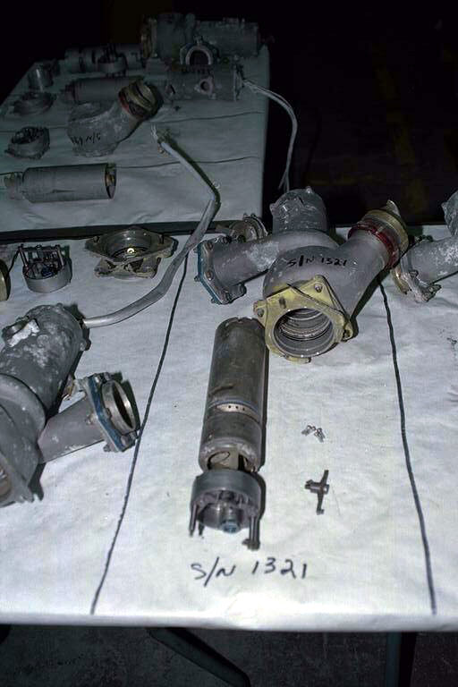
The valve consists of two parts: the valve body, which is inside the upper auxiliary tank, and the motor actuator assembly, which can be replaced externally. The valve, heavily damaged, was recovered in several pieces. A "T" section of the fuel piping was still attached to the valve body and was used to identify the valve as being part of the auxiliary tank fill/isolation valve. The valve slide was retained within the housing and was captured in the CLOSED position.
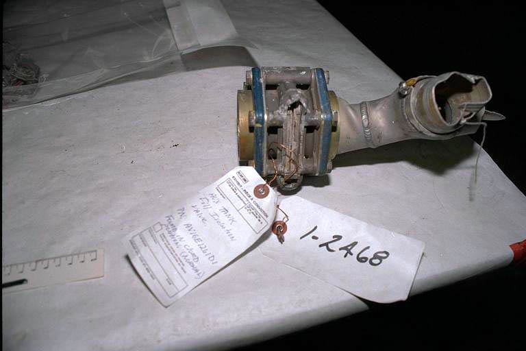
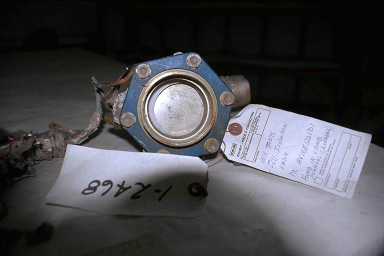
The electrical valve motor actuator assembly and related portion of the slide housing were broken off the valve, but were recovered in a section of the auxiliary fuel tank aft wall structure that houses the auxiliary tank fill/isolation valve. The housing cover had been crushed against the valve actuator and housing.

The electrical valve actuator was identified by tag as ITT Aerospace Controls PN AV16E1261D1, SN RN34888. The red external handle on the actuator had received an impact blow from the crushing of the housing cover. The handle/shaft retention pin was sheared, and the handle was moved part way out of the CLOSED position.
The valve has a "mean time between unscheduled removals" rate of 64 175 hours (the same as its "mean time between removals rate"). The actuator assembly has a mean time between unscheduled removals rate of 33 194 hours and a mean time between removals rate of 25 534 hours. Boeing has no data on "confirmed" failures versus "no fault found" failures and, therefore, no "mean time between failures" number.
Tail tank fill/Isolation valve
The tail tank fill/isolation electrically actuated gate valve was recovered in a section of the tail fuel tank assembly. The tank mount body assembly was identified as PN 125088E, SN N49896. The valve slide was captured within the valve body and was in the CLOSED position.

The valve actuator housing cover was crushed, causing the electrical valve actuator to break away from the valve. The red actuator handle was aligned with the valve CLOSED position.

The actuator support assembly was identified as PN 125144E, SN 51728.
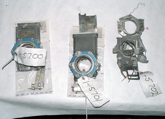
Fuel crossfeed valves
The valves were identified by tag as PN AV16E1261D1. The electrical actuators on all three valves were broken off and were not recovered or identified. The valve slide in Exhibit 1-5702 was captured in a mid-open position; however, the position of the slide at the time of impact could not be determined. The valve slides from exhibits 1-5700 and 1-5701 were torn from the valve bodies. A valve slide belonging to either Exhibit 1-5700 or Exhibit 1-5701 was recovered, but it could not be determined which exhibit it belonged to. A determination of the valve slide positions at the time of impact could not be made.
Fuel pump
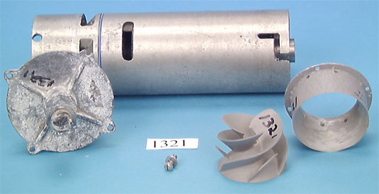
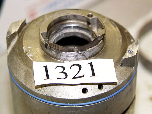
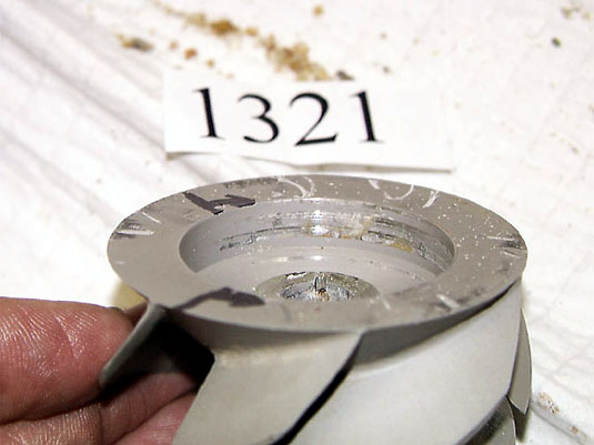
All 17 fuel pumps were recovered and taken to the manufacturer's facility (Hydro-Aire, Burbank, California) for examination. The objective of the fuel pump examination was to determine whether the fuel pumps were running at the time of impact. As each pump in each fuel tank is powered by a different electrical power source, it was felt that a determination of pump operation could lead to a better understanding of the aircraft's electrical power distribution at the time of impact.
The condition of the component parts indicated that all 17 pumping units were capable of operating at the time of impact; however, pump SN 7186 would have had reduced performance owing to an open thermal fuse in the phase "A" winding. The pumping units are able to operate with one phase winding inoperative; the reduction in pump performance would not have affected engine operation.
Of the 17 fuel pumps, 15 were matched to a position in the aircraft by SN, by physical matching of the pump flanges, or both. The locations of the remaining two pumps, SN 0908 and SN 1337, were determined by a process of elimination to have been from either the Tank 2 forward boost position or the Tank 3 aft boost position. The fuel pump positions, electrical power sources, and operational status at the time of impact are shown in the following table.
| Pumping Unit Position | SN | Electrical Power Source | Operational Status |
|---|---|---|---|
| Tank 1 Forward Boost | 7186 | 115 V AC Generator Bus 1 | Operating |
| Tank 1 Aft Boost | 6185 | 115 V AC Generator Bus 3 | Operating |
| Tank 1 Transfer | 7153 | 115 V AC Generator Bus 2 | Undetermined |
| Tank 2 Forward Boost (or) Tank 3 Aft Boost |
9e+06 | 115 V AC Generator Bus 1 115 V AC Generator Bus 2 |
Undetermined |
| Tank 2 Right Aft Boost | 9115 | 115 V AC Generator Bus 2 | Not Operating |
| Tank 2 Left Aft Boost | 7189 | 115 V AC Right Emergency Bus | Undetermined |
| Tank 2 Transfer | 7313 | 115 V AC Generator Bus 3 | Operating |
| Tank 3 Forward Boost | 2252 | 115 V AC Generator Bus 3 | Undetermined |
| Tank 3 Transfer | 6853 | 115 V AC Generator Bus 1 | Operating |
| Upper Auxiliary Left Transfer | 6419 | 115 V AC Generator Bus 2 | Undetermined |
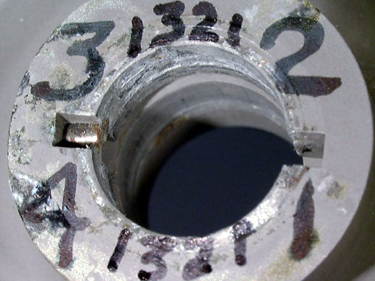
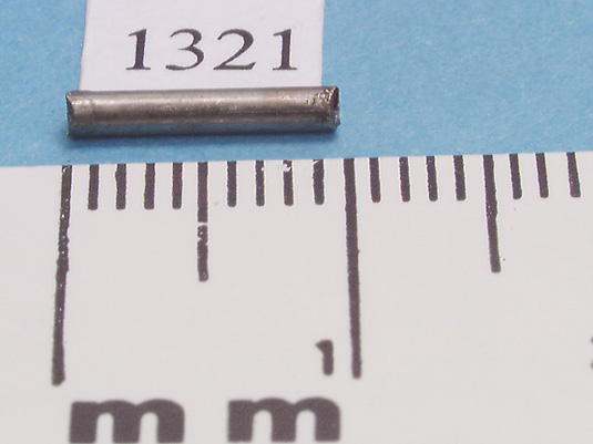
| Upper Auxiliary Right Transfer | 1321 | 115 V AC Generator Bus 1 | Operating |
| Lower Auxiliary Left Transfer | 6885 | 115 V AC Generator Bus 2 | Undetermined |
| Lower Auxiliary Right Transfer | 6958 | 115 V AC Generator Bus 3 | Undetermined |
| Tail Tank Left Transfer | 3631 | 115 V AC Generator Bus 1 | Operating |
| Tail Tank Right Transfer | 2011 | 115 V AC Generator Bus 2 | Undetermined |
| Tail Tank Alternate Boost | 7720 | 115 V AC Right Emergency Bus | Undetermined |
Fuel pump operation
Determination
Tank 1
Engine supply pumps
The operation of both the Tank 1 forward and Tank 1 aft boost pumps was as expected.
Fuel transfer pump
It could not be determined whether the pump was running at the time of impact. The pump would normally come on only if there was a need for fuel balancing; therefore, it may not have been running.
Tank 2
Engine supply pumps
It could not be determined whether the Tank 2 forward and Tank 2 left aft fuel boost pumps were running at the time of impact. Examination of the Tank 2 right aft boost pump determined that the pump was likely not running at the time. In assessing the operating status of the pumps, the shutdown of Engine 2 and the position of the Engine 2 FUEL switch must be taken into account. If the Engine 2 FUEL switch was in the ON position, then all three Tank 2 boost pumps should have been operating at the time of impact. However, if the Engine 2 FUEL switch was in the OFF position, all three engine supply boost pumps would be expected to be off.
A less likely reason for the Tank 2 boost pumps to be off would be if the FSC were attempting to send fuel to Engine 2 from the main manifold because it was unable to use the Tank 2 fill valve. In that instance, Crossfeed Valve 2 should have been open. The positions of the crossfeed valves could not be determined from a physical examination.
Fuel transfer pump
One possible reason for the Tank 2 transfer pump to be operating would be for the rebalancing of the main tanks. Tank 2 was already approximately 1 500 lb higher than tanks 1 or 3, as discussed in Fuel Schedule Management. With the imbalance logic active, tanks 1 and 3 would need to be increased. There are two ways for this to occur. If the upper auxiliary tank quantity was below 2 100 lb, the Tank 2 transfer pump would move fuel from Tank 2 to Tank 1 or Tank 3. Any fuel coming from the upper auxiliary tank would go to whichever tank was being filled. If the fuel quantity in the upper auxiliary tank were equal to or greater than 2 100 lb, then the fuel supply to correct the imbalance would come only from the upper auxiliary tank and the Tank 2 transfer pump would not be expected to be operating. The FSC would disarm the fill valves of the two heavier main tanks and only transfer fuel from the upper auxiliary tank to the lightest main tank until the imbalance was corrected. It is also necessary to note that if Tank 2 were sending fuel to other main tanks, as evidenced by the running transfer pump, it would not have been simultaneously receiving fuel to the engine through its crossfeed valve as mentioned in the paragraph above.
Tank 3
Engine supply pumps
It could not be determined whether the Tank 3 forward and Tank 3 aft fuel boost pumps were running at the time of impact. Both pumps should have been operating. If they were not, the loss of the pumps could be related to a loss of electrical power or from having been faulted by the FSC. The Tank 3 forward boost pump is powered by the 115 V AC Generator Bus 3 and the Tank 3 aft boost pump by the 115 V AC Generator Bus 2. If there was an electrical power problem with the 115 V AC Generator Bus 2 and it extended to the DC Bus 2 as well, then both the Tank 1 and Tank 3 outboard fill valves and the Tank 2 crossfeed valve should also have been inoperative.
Fuel transfer pump
One possible reason for the Tank 3 transfer pump to be operating would be if the FSC were rebalancing the main tanks and sought to supply fuel from Tank 3. A less likely cause of pump operation would be if the FSC inputs caused the FSC to be in its take-off/land flight phase with the Tank 3 aft pump faulted or without power. In that case, the FSC would command the transfer pump on and the crossfeed valve open, to provide fuel from the aft located pump. In that situation the forward pump should also be operating.
Upper auxiliary tank
It could not be determined whether the upper auxiliary tank left transfer pump was running at the time of impact. As the upper auxiliary tank right transfer pump was determined to have been operating, the left pump should also have been operating. The FSC logic always seeks to use both transfer pumps in the auxiliary tanks when it is transferring fuel.
Lower auxiliary tank
It could not be determined whether the two lower auxiliary tank transfer pumps were running at the time of impact. The lower auxiliary tank should not have contained fuel, so the two fuel transfer pumps in that tank should not have been running.
Tail tank
It could not be determined whether the tail tank right transfer pump was running at the time of impact. Since the tail tank left transfer pump was determined to be operating, the right pump should have been operating as well. The FSC logic always attempts to use both transfer pumps in the tail tank when it is transferring fuel from the tank.
It could not be determined whether the tail tank alternate pump was running at the time of impact. The alternate pump is used to supply fuel directly to Engine 2. With Engine 2 shut down, there would be no need for the alternate pump to be running.
Summary
With the FSC operating in Auto mode, between 8 and 11 of the 17 fuel pumps should have been operating at the time of impact. This was derived from a calculation of the aircraft fuel load and distribution at the time of impact, combined with the effects of fuel balancing, the shutdown of Engine 2, and the closed positions of the fuel dump valves. The six fuel pumps that were deemed to be operating at the time of impact were from this category of 8 to 11 pumps. The fact that the remaining pumps in this category could not be classified as operating at the time of impact does not mean that some of them were not, but rather that there was insufficient rotational damage to make this assessment.
Fuel pumping unit SN 9115, which displayed markings to suggest that it was not operating at the time of impact, was determined to be from the Tank 2 right aft boost position. This pump, along with the two remaining engine feed pumps in Tank 2, are designed to be shut off by the fuel system controller if the controller is in the Auto position and the corresponding engine is shut down with the engine FUEL switch.
Fuel management
Examination
Fuel schedule conditions
The expected fuel system operation for SR 111 was analyzed using information from the wreckage, and with the following data and assumptions:
Final ACARS Loadsheet No. 1943 for SR 111 (2 September 1998; JFK-GVA; HB-IWF).
Zero fuel weight 176 847 kg Take-off weight 241 147 kg Fuel at take-off 64 300 kg Zero fuel weight MAC 19,8 % Fuelling Order for SR 111 (2 September 1998; JFK-GVA; HB-IWF).
Charge totale de carburant de 65 300 kg à une densité de 0,805 Tank 1 18 450 kg Tank 2 27 550 kg Tank 3 18 350 kg Upper auxiliary tank 850 kg* Tail tank 100 kg A density of 6.76 lb per US gallon (specific gravity of 0.810)* was used to estimate the fuel quantity distributions in the tanks. Once airborne, the density would tend to increase as the fuel cooled.
*Note: The specific gravity estimate of 0.810 was used before information from the fuelling order became available. A slightly lower specific gravity (0.805 from the fuelling order) would result in tanks 1 and 3 being full at a slightly lower reading (approximately 41 000 lb) than the 41 300 lb assumed in the summary. This would slightly delay, by perhaps 1 to 2 minutes, the transition from Tank 2 Excess Transfer to All Mains Equal, which occurred approximately 17 minutes after take-off, as described in Fuel Schedule Management Determination, below.
- The following data file from the DFDR:
Time span: From approximately 17 minutes prior to take-off until the recorder stopped.
Parameters:
UTC (h/min/s)
pressure altitude (in feet)
gross weight (in pounds)
total fuel quantity (in pounds)
C of G (% MAC) - The incorporation of Service Bulletin 28-092 on 12 September 1997, which changed the C of G control margin from 2.5% to 2%.
- The fuel system was operating in the automatic mode for the entire flight, with the fuel pumps and valves being controlled by the FSC or the FUEL DUMP push button (if selected).
- The tail tank and auxiliary tank fill/isolation valves were in the closed position at the time of impact.
- The Tank 1 forward and aft boost pumps, the Tank 2 transfer pump, the Tank 3 transfer pump, the upper auxiliary right transfer pump and the tail tank left transfer pump were running at the time of impact. The Tank 2 right aft boost pump was likely not running at the time of impact. An assessment of the operational status of remaining pumps was inconclusive as a result of the lack of rotational damage.
- The positions of the three fuel system crossfeed valves could not be determined.
- The slats and landing gear were in the retracted position at the time of impact.
- FADEC fault information indicated that Engine 2 had been shut down with the FUEL switch prior to impact.
- For the purpose of simplifying the estimation of tank quantities, it was assumed that tanks 1 and 3 were kept full continuously by Tank 2 during the early part of the flight. These tanks will refill periodically, as the high-level shutoff floats allow the fill valves to open. During the early part of the climb, the quantity in these tanks may decrease by 1 000 to 2 000 lb before the floats allow refilling. This is primarily owing to the high nose-up attitude during take-off and initial climb. In the later portion of climb and during cruise, the tanks tend to refill once they are 500 to 1 000 lb below full. Therefore, individual fuel tank quantity estimates are approximate and could vary by ± 1 000 lb.
- The aircraft was equipped with a −907 FSC. The −907 FSC is designed to transfer tail fuel forward as the aircraft descends through 26 750 feet with a minimum initial descent rate of more than 600 fpm, then a steady rate of more than 400 fpm with more than 500 lb of fuel in the tail and less than 90 000 lb of fuel on board. With more than 90 000 lb of fuel on board (as in the case of SR 111) and under the same descent rate conditions, the −907 FSC would start this tail fuel forward transfer sequence as the aircraft descended through 19 750 feet.
*Note: After engine start and prior to take-off, there would be a short period when the FSC was transferring the 850 kg (1 900 lb) of upper auxiliary tank fuel to the main tanks. Total fuel from the fuelling invoice was 65 300 kg (144 000 lb) and fuel on board at take-off (from the FDR) was approximately 64 300 kg (142 000 lb); therefore, the transfer of fuel from the upper auxiliary fuel tank should have been complete and only main tank fuel would have remained by the time the flight departed New York.
Determination
Fuel schedule management
The data on the DFDR begins approximately 17 minutes prior to take-off, with the total fuel quantity at 143 200 lb. C of G is at 23.2% MAC. This was assumed to be just after engine start. Normal fuel distribution at this time would be as follows: tanks 1 and 3 both full, with approximately 41 300 lb in each, and Tank 2 with approximately 60 600 lb (approximately 93% full). The upper and lower auxiliary tanks and the tail tank would be empty. In this condition, the FSC would have the aft boost pumps operating in all three main tanks (four pumps in total). In addition, the Tank 2 transfer pump would be operating and the fill valves of tanks 1 and 3 would be armed. This would allow fuel from Tank 2 to transfer to tanks 1 and 3 as the high-level shut-off floats in those tanks permitted the fill valves to open. This is normal fuel scheduling where the extra fuel in Tank 2, which has more capacity that tanks 1 and 3, is transferred to tanks 1 and 3 until all three main tanks are equal.
The total fuel quantity at take-off was 142 000 lb, with a C of G of 23.4% MAC. In take-off, the FSC will turn on the forward boost pumps in the main tanks. The aft boost pumps and the Tank 2 transfer pumps would remain on and the fill valves for tanks 1 and 3 would remain armed. Estimates of the fuel quantities in the main tanks at this time would be 41 300 lb in each of tanks 1 and 3, and 59 400 lb in Tank 2.
Once the landing gear and slats have both been retracted, the FSC would exit its take-off/landing flight phase. The forward boost pumps in the main tanks would be turned off and tail fuel management would begin. With the fuel distribution at take-off, the FSC would initially begin filling the tail tank with the extra fuel from Tank 2. The Tank 2 transfer pump would be used for this process. The auxiliary and tail fill/isolation valves would be opened and the tail tank fill valve would be armed and opened to fill the tail tank. The DFDR data shows the C of G beginning to move aft approximately 3 to 4 minutes after take-off.
During the process of filling the tail tank, the quantity in Tank 2 would become equal with tanks 1 and 3. This condition is estimated to have occurred approximately 17 minutes after take-off at a total quantity of 130 800 lb with the C of G at 27.2% MAC. At this time tanks 1, 2, and 3 would contain approximately 41 300 lb each and the tail tank would contain approximately 7 000 lb of fuel. When this condition occurred, the FSC would change configurations. The Tank 2 transfer pump would remain on, but the fill valves for tanks 1 and 3 would be disarmed. Tanks 1 and 3 transfer pumps would be turned on and fuel would now be supplied to the tail tank from all three main tanks.
The next fuel system event on the DFDR data is the occurrence of a normal water scavenge transfer from the tail tank. This occurred approximately 30 minutes after take-off, with the total fuel quantity at 127 200 lb. At this time tanks 1, 2, and 3 would contain approximately 38 000 lb each and the tail tank approximately 13 000 lb, with the aircraft C of G at 31.3% MAC. The FSC would then reconfigure the fuel system in the following sequence: there would have been no change to the main tank boost pumps; that is, the aft pumps would be on and the forward pumps off; the tail tank's fill valve and the tail tank fill/isolation valve would be disarmed and closed; the auxiliary tank fill/isolation valve would remain open; the two tail tank transfer pumps would be turned on and the three main tank transfer pumps would be turned off; the Tank 2 fill valve would be armed and fuel would be transferred from the tail tank to Tank 2.
After approximately 1 500 lb of fuel were transferred, the transfer out of the tail would be discontinued. The tail would then be refilled with fuel from all three main tanks. The DFDR data indicates that the refill process began approximately 3 to 4 minutes after the forward transfer started. The re-configuration would be as follows: the Tank 2 fill valve would be disarmed and closed; the tail tank fill valve and tail tank fill/isolation valves would be reopened; the main tank transfer pumps would be turned on; and the tail transfer pumps would be turned off. When this process was completed, approximately 38 minutes after take-off, the total fuel quantity was at 124 000 lb. At this time tanks 1 and 3 would contain approximately 36 400 lb, Tank 2 approximately 37 900 lb, and the tail tank approximately 13 000 lb. The FSC would not rebalance the main tanks unless there was at least a 2 400 lb difference between any two main tanks.
The aircraft reached the top of its climb approximately 39 minutes after take-off, with the C of G at 31.6% MAC. The aircraft C of G was at the forward end of its 2.0% control margin, indicating that the tail tank had been completely filled. (See chart of "Centre of Gravity (C of G) data plot.") The FSC would then discontinue fuel transfer to the tail tank and would close/disarm the tail tank fill valve and the auxiliary tank and tail tank fill/isolation valves. All of the main tank transfer pumps would be turned off. Only the aft boost pumps in the main tanks would remain on, and all valves would be closed. The total fuel quantity at this time was 123 200 lb. The estimated tank quantities were 36 100 lb in tanks 1 and 3, 37 600 lb in Tank 2, and 13 400 lb in the tail tank.
The aircraft continued in cruise for another 19 minutes until the descent began, approximately 58 minutes after take-off. The total fuel quantity was 118 200 lb and the aircraft C of G was 31.5% MAC. Fuel distribution should have been approximately 34 400 lb in tanks 1 and 3, 36 000 lb in Tank 2, and 13 400 lb in the tail tank. In the initial descent, the only change to the fuel system configuration would be that the FSC would turn on the forward boost pumps in the main tanks.
Fuel transfer out of the tail tank would begin when the aircraft's altitude decreased below 19 750 feet. This altitude transition occurred approximately 1 hour and 3 minutes after take-off. Total fuel quantity was 117 600 lb and the aircraft C of G was at 31.5% MAC. Fuel distribution should have been approximately 34 200 lb in tanks 1 and 3, 35 800 lb in Tank 2, and 13 400 lb in the tail tank. The FSC's primary selection for a transfer path would be to send the tail fuel directly to the main tanks by opening the auxiliary fill/isolation valve, thereby executing the tail transfer task while staying on schedule and avoiding a rescheduling task. Since the auxiliary fill/isolation valve was found in the closed position and the upper auxiliary tank right transfer pump was operating, the FSC had probably moved to its second choice in the transfer path, which would turn on the two tail transfer pumps and move fuel from the tail tank directly to the upper auxiliary tank. Once the fuel level in the upper auxiliary tank was above 700 lb for more than 20 seconds, the FSC would command the upper auxiliary tank pumps on to begin to move fuel to the main tanks. Initially, while the quantity of fuel in the upper auxiliary tank was less than 2 100 lb, the FSC would treat this transfer as a "purge" of the upper auxiliary tank. As such, the FSC would arm the Tank 2 fill valve and open the Tank 1 and Tank 3 outboard fill valves. The upper auxiliary tank would not immediately transfer fuel to the main tanks. This tank is very large, and it takes some time for the fuel to make its way from the fill valve outlet to the pump inlets. Once the fuel pumps begin to pick up fuel, they may transfer intermittently. Therefore, while the flow of fuel into the tank would be steady, the flow of fuel out of the tank would not be steady, initially. The quantity would tend to continue to increase in the upper auxiliary tank until the pump inlets in that tank were continuously covered with fuel. If the quantity rose to 2 100 lb or more, the FSC would change the condition of the tank from a "purge" to a "low" tank with an off-schedule condition. This would cause the outboard fill valves to be closed and all three main tank fill valves to be armed.
For the next five minutes (until the end of the FDR data) the aircraft C of G began a steady forward movement. During this time aircraft C of G moved from 31.5% MAC to 29.5% MAC. This is consistent with the movement of approximately 3 000 to 3 500 lb of fuel out of the tail tank. The last total fuel quantity in the FDR data was 116 200 lb, and the last aircraft C of G was 29.5% MAC. Fuel transfer out of the tail tank should have continued until either the slats or the landing gear were extended. Without the extension of either the slats or landing gear, fuel transfer should have continued until the time of impact, at which time the tail tank would have contained 5 000 to 7 000 lb of fuel.
Auxiliary tank fill/Isolation valve
Closed scenarios
The determination that the auxiliary tank fill/isolation valve was in the closed position when the flight ended was unexpected. As discussed in the previous section, fuel should have been transferring from the tail tank to the main tanks through this valve. Finding it closed suggests that either the FSC sensed that there was still fuel in the upper auxiliary tank, that the valve had failed or was without electrical power to open, or that a fuel dump had been initiated.
If, for some reason, the FSC did not initiate or complete the 850 kg transfer of fuel from the upper auxiliary tank to the main tanks after engine startup, then the FSC would send fuel from the tail tank to the upper auxiliary tank. This scenario is unlikely, as the FSC would sense an off-schedule condition and would continually try to remove this fuel. If it could not, the FSC would have reverted to manual mode during the early part of the flight, which is not supported by DFDR information.
It is possible that the valve failed, but is unlikely, as DFDR data show that the valve was operating properly approximately 37 minutes into the flight, during the tail fuel tank fill process and the tail tank water scavenge cycle.
Electric power for the auxiliary tank fill/isolation valve is redundantly supplied from the battery bus and the battery direct bus. A loss of power to both of these buses or loss of individual circuits could account for the valve being closed; however, the loss of power would have to have occurred prior to the start of the tail fuel transfer, as the aircraft was descending through 19 750 feet. DFDR information does not support a loss of these buses at that time.
The FSC controls the auxiliary tank fill/isolation valve through Relay R2-5272. The control circuitry for Relay R2-5272 is installed below the floor from the main avionics rack shelf to the centre accessory compartment in an area that showed no heat or fire damage. Relay R2-5272 receives its power from the battery bus through the fuel tank fill valves and Battery Bus Sensing CB B1-474 at location B-29 on the overhead CB panel. Relay R2-5272 is redundantly powered by the battery direct bus through the Ground Refuel Power CB B1-475 at location A-29 on the overhead CB panel. Both of these CBs were located in an area of high heat, in the range of 650 to 1 150°F. CBs trip at approximately 350°F, making the thermal tripping of these CBs a likely event. The fuel tank fill valves and Battery Bus Sensing CB B1-474 was recovered with soot accumulation on the white CB indicator ring, which indicates that the CB had tripped some time before impact. The Ground Refuel Power CB B1-475 was not recovered. The CBs are located on the outer right edge of the upper two rows of the overhead CB panel beyond a bend in the panel and in an area behind and above the flight crew seats. The CBs are difficult for the flight crew to see while they are seated in the their seats.
The power wires for the auxiliary tank fill/isolation valve from CBs B1-474 and B1-475 are located in the same wire runs (AMP, AMK, and AMJ) from the overhead CB panel, through the exit hole in the right side of the overhead switch panel, to connector P1-398 (pins "e" and "g") on the right overhead disconnect switch panel located behind the avionics upper CB panel. These wires are co-located in the wiring run AMK, which was known to have an electrical arcing event outside of the overhead switch panel
During simulator trials, the fuel tank fill valves and Battery Bus Sensing CB B1-474 and the Ground Refuel Power CB B1-475 were tripped to see what cockpit indications occurred. Neither CB trip provided an alert on the DU-3 EAD, nor a cue light on the SDCP. When the status page on the SDCP was manually selected, a Level 1 maintenance alert on the synoptic page on DU-4 appeared, indicating a Fuel Valve Fault. If the status page was not selected, the Fuel Valve Fault would remain a hidden event to the crew. The DFDR did not record a status page selection during the flight; however, this parameter is only sampled every 64 seconds.
When a fuel dump is initiated, the auxiliary tank fill/isolation valve is commanded closed. In this case, with tail fuel being transferred forward, the auxiliary tank fill/isolation valve should have been open, and would have been commanded closed. The tail fuel would then be re-directed to the upper auxiliary tank. When 2 100 lb of fuel had been transferred to the upper auxiliary tank, the FSC would have been configured to the "Reschedule" mode. In the "Reschedule" mode, if the fuel dump was terminated, the FSC would not attempt to re-open the auxiliary tank fill/isolation valve and the auxiliary tank fill/isolation valve would be expected to be in the closed position at the time of impact.
If it can be established that fuel dump had been started, then the normal FSC command to close the auxiliary tank fill/isolation valve would be the most likely reason for the valve to be in the closed position at the time of impact.
If fuel dump had not taken place, then the most likely reason for the valve to be closed at the time of impact would be that the valve was without electrical power to open.